


← Corbin
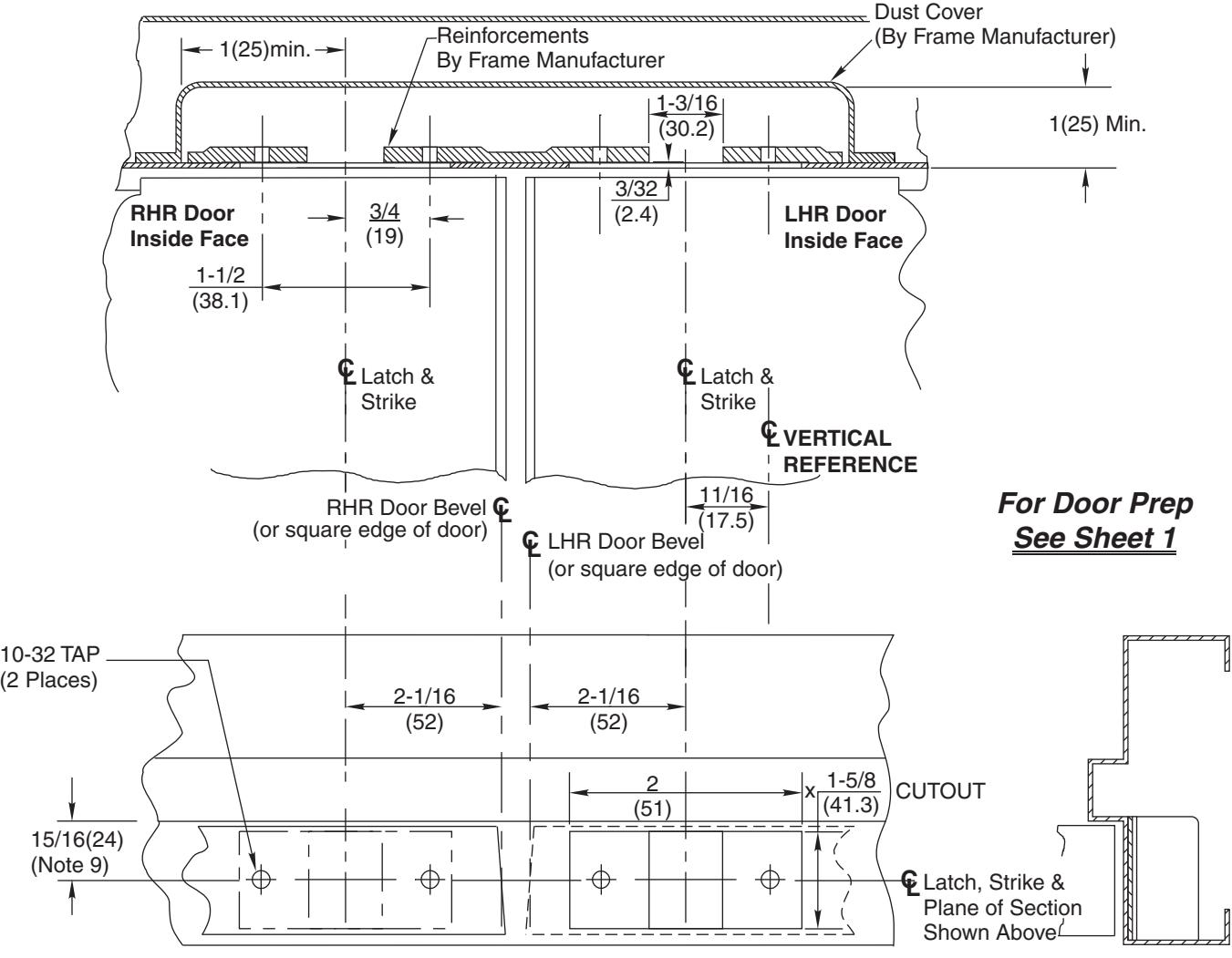
681F77 Top Strike Preparation (See Note 6)
Notes:
- Do not scale drawing. 1.
- Dimensions are in inches (mm). 2.
- Preparation is typical for both hands. 3.
- Minimum door stile width: 4-1/2 (114). 4.
- Prepare mounting holes when installing the device. 5.
- Drawing shows elevation (frame bisected on strike center), bottom view looking up and side view. 6.
- Provide adequate structural support to maintain door integrity after device installation with power tools, door use, or abuse. 7.
- For recommended door reinforcements see template T30800. 8.
- Door located in frame for door silencers. If not used, compensate this dimension to seat the door against the stop without rattle. 9.
- Device mount to hinge stile (not shown) requires hole location and preparation during device installation. 10.
- For outside trim preparation see appropriate trim template. 11.
- For electrical devices (suffixes M91, M92, M93, M94, M97) also see template T30890. 12.
- Holes for optional SNB (Required for unreinforced doors): 9/32 (7.00) dia., inside door face; 3/8 (9.50) dia., outside door face. 13.
- For Fire Labeled Door Pairs Only: Active leaf: 5/8 (16) Dia. x 7/8 (22) Deep Min. Inactive leaf: 9/16 (14) Dia. x 2-7/8 (73) Deep Min. Reinforce door as needed for heat activated interlocking bolt. 14.
- 5/8 (16.00) dia. x 3/4 (19) deep hole in floor, required. 15.
- For M55 option, omit bottom door prep, and floor strike. 16.
- Maximum thickness 5/32 (4.0) when outside escutcheon trim is used. 17.
- Bottom bolt should retract to 1/8 (3.2) above floor strike. Floor coverings in the door path must be laid accordingly. 18.
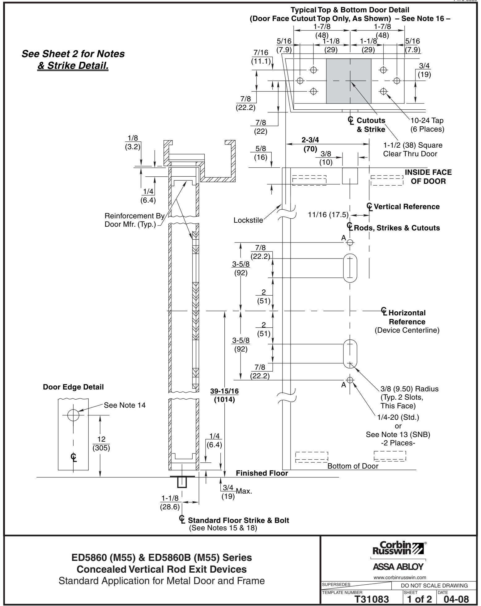
ED5860 (M55) ED5860B (M55) Series Concealed Vertical Rod Exit Devices &
Standard Application for Metal Door and Frame
SUPERSEDES DO NOT SCALE DRAWING TEMPLATE NUMBER DATE www.corbinrusswin.com ASSA ABLOY SHEET
04-08
T31083 2 of 2