← Corbin
Notes:
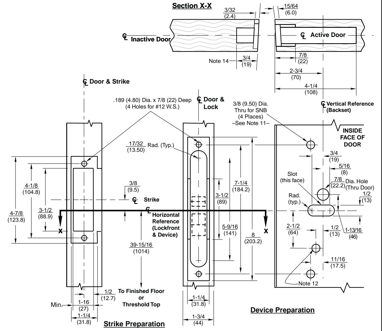
- 1. Do not scale drawing.
- 2. Dimensions are in inches (mm).
- LHR active pair shown. Preparation is typical for both hands.
- 4. Minimum door stile width 4-1/2(114).
- 5. Prepare mounting holes when installing device.
- Provide adequate structural support to maintain door integrity after device installation with power tools, door use, or abuse.
- Device mount to hinge stile (not shown) requires hole(s) location and preparation during device installation.
- For outside trim preparation see appropriate trim template.
- Unless otherwise specified, door preparation and dimensional tolerances must conform to ANSI A115.1W.
- 10. Dimensions given about a centerline are symmetrical.
- Wood screws (#14x1-1/4", by others) permitted in solid core wood doors if pilot holes are used for installation when door label allows its use.
- For electrical devices suffixes "-Safe", "-Secure", M91, or M93: 1/2 (12.70) diameter thru this face, plus prep shown on template T30890.
- 13. For electrical device suffixes M92, M94, or M97 also see template T30890.
- 14. Dimension is 1 (25) if dust box is used.
- 15. Latchbolt centerline is 23/32 (18.2) below & Auxbolt centerline is 3/16 (4.8) above the centerline of lockfront.
ED5602 & ED5602A Series Double Cylinder Mortise Exit Devices with ANSI A115.1 Strike & Optional SNB Application for Pair of Wood or Composite Doors without Mullion