


← Corbin
Notes:
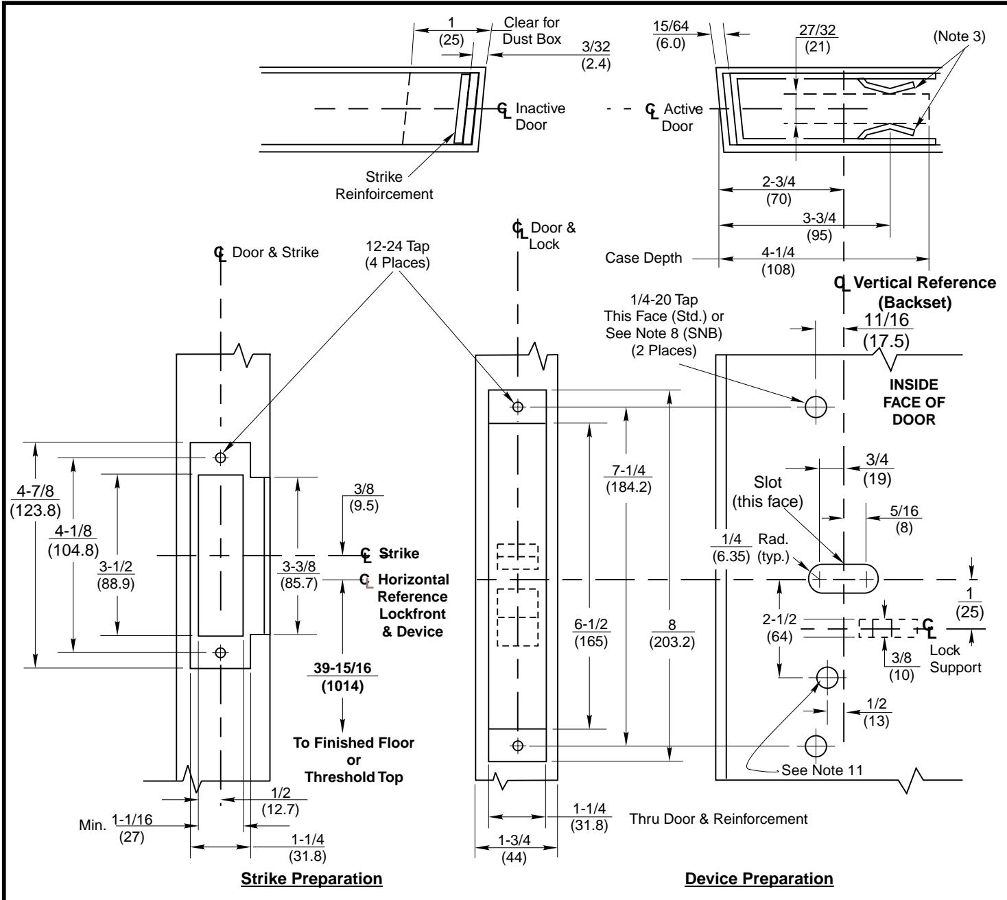
- 1. Minumum Stile Width 4-1/2(114).
- For door reinforcements see template T30800. Unreinforced doors require optional SNB to mount devices.
- Unless otherwise specified, door preparation and dimensional tolerences must conform to ANSI A115.1. Lock support required as shown.
- 4. For outside trim preparation see appropriate trim template.
- 5. Prepare mounting holes when installing the device.
- LHR active pair shown. Preparation is typical for both door hands
- 7. Dimensions are in inches (mm). Do not scale drawing.
- Holes for optional SNB: 9/32(7.00)Dia. inside door face; 3/8(9.50) Dia. outside door face.
- 9. Dimensions given about a centerline are symmetrical.
- 10. Device mount to hinge stile (not shown) requires holes location and preparation during device installation.
- 11. For Electrical device suffixes "-Safe", "-Secure", M91, or M93: 1/2 (12.70) diameter, this face, plus prep shown on template T30890.
- 12. For electrical device suffixes M92, M94 or M97 also see template T30890.
- 13. Latchbolt centerline is 23/32 (18.2) below & Auxbolt centerline is 3/16 (4.8) above the centerline of lockfront.
ED5600 & ED5600A Series Mortise Exit Devices with ANSI A115.1 Strike
Application for Pair of Metal Doors without Mullion

www.corbinrusswin.com
SUPERSEDES T30810
DO NOT SCALE DRAWING
T30810-1
0810-1 | DATE 9-99