← Corbin
Notes:
- 1. Do not scale drawing.
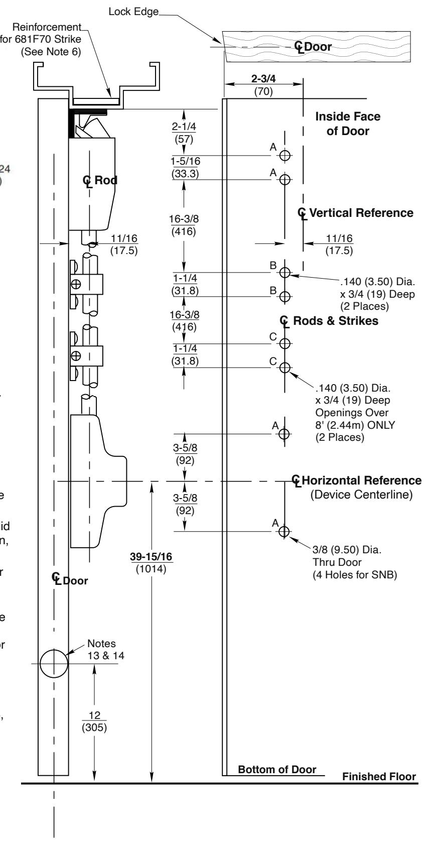
- 2. Dimensions are in inches (mm).
- 3. LHR door shown. Preparation is typical for both door hands.
- 4. Minimum door stile width 4-1/2(114).
- 5. Prepare mounting holes when installing the device.
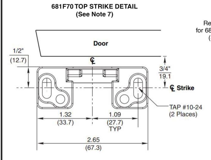
- 6. Unreinforced frames require blind rivet nuts (by others) to mount the strike.
- 7. Door in frame with door silencers. Compensate strike distances for other conditions.
- 8. Wood screws #14x1-1/2" (by others) permitted in solid core wood doors if pilot holes are used for installation, when door label allows its use.
- 9. Provide adequate structural support to maintain door integrity after device installation with power tools, door use, or abuse.
- 10. Device mount to hinge stile (not shown) requires hole location and preparation during device installation. Door structural requirements are similar for both door stiles.
- 11. For outside trim preparation see appropriate trim template.
- 12. For electrical devices (suffixes M91, M92, M93, M94, M97) also see template T30890.
- 13. For Labeled Door Pairs Only Active Leaf: 5/8 (16) Dia.x1-1/4 (32)Deep Inactive Leaf: 9/16 (14) Dia.x1-5/8 (41) Deep
- 14. Door structure as required for heat activated interlocking bolt. 1-1/2 square 16 ga. plate recommended.
Surface Vertical Rod Exit Devices ED5470 M55 & ED5470B M55 Series
Less Bottom Rod (M55 Option) Application for Wood or Composite Door and HM Frame and