← Corbin
Notes:
- 1. Do not scale drawing.
- 2. Dimensions are in inches (mm).
- LHR door shown. Preparation is typical for both door hands.
- 4. Minimum door stile width 4-1/2(114).
- 5. Prepare mounting holes when installing the device.
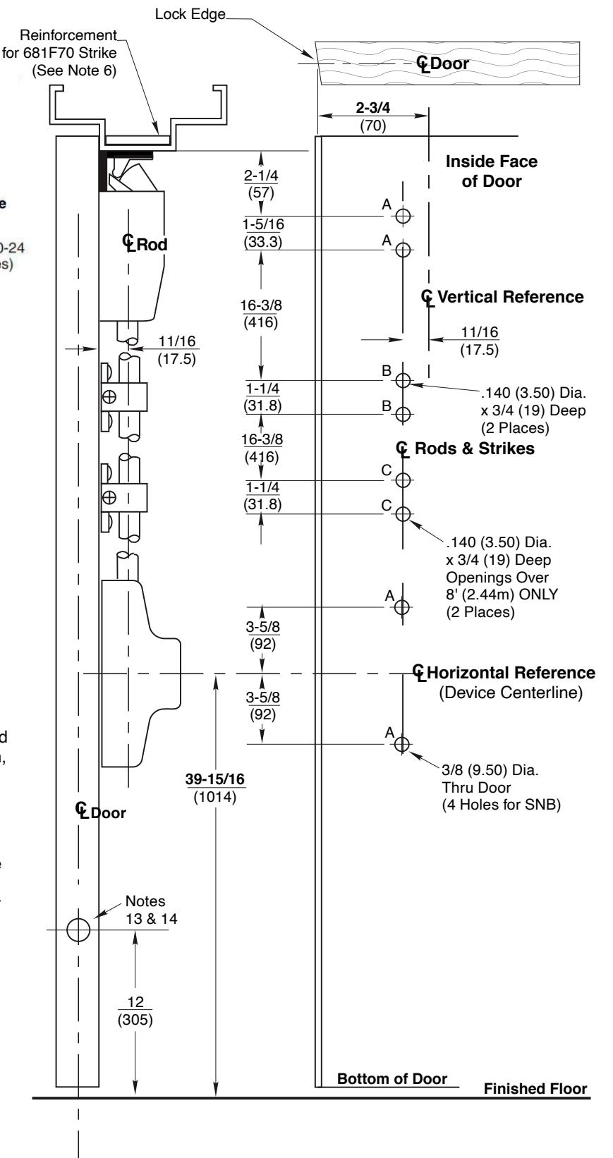
- Unreinforced frames require blind rivet nuts (by others) to mount the strike.
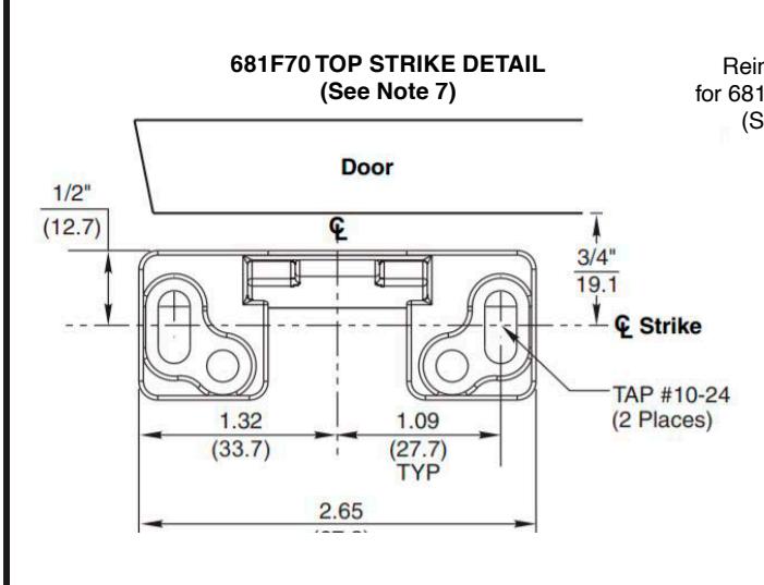
- 7. Door in frame with door silencers. Compensate strike distances for other conditions.
- 8. Wood screws #14x1-1/2" (by others) permitted in solid core wood doors if pilot holes are used for installation, when door label allows its use.
- Provide adequate structural support to maintain door integrity after device installation with power tools, door use, or abuse.
- Device mount to hinge stile (not shown) requires hole location and preparation during device installation. Door structural requirements are similar for both door stiles
- 11. For outside trim preparation see appropriate trim template.
- For electrical devices (suffixes M91, M92, M93, M94, M97) also see template T30890.
- 13. For Fire Labeled Door Pairs Only: Active Leaf: 5/8 (16) Dia. x 7/8 (22) Deep Min. Inactive Leaf: 9/16 (14) Dia. x 2-7/8 (73) Deep Min.
- Door structure as required for heat activated interlocking bolt. 1-1/2 square 16 ga. plate recommended.
ED5470 M55 & ED5470B M55 Series Surface Vertical Rod Exit Devices tion for Wood or Composite Door and HM Fran
Application for Wood or Composite Door and HM Frame and Less Bottom Rod (M55 Option)