


Installation Instructions

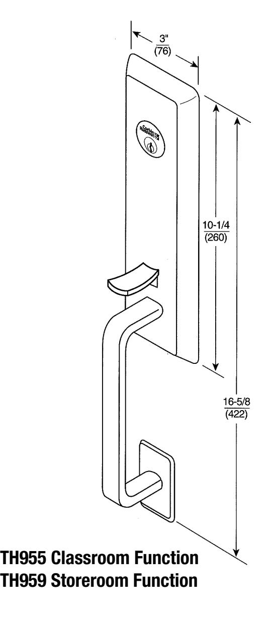
TH955 & TH959
Heavy Duty Thumbpiece Trim For use with ED5000 Series Exit Device
Metal, Wood or Composite Doors
For ED5000 Series Exit Device
Installation Instructions

For installation assistance contact Corbin Russwin 1-800-543-3658 • techsupport.corbinrusswin@assaabloy.com
For ED5000 Series Exit Device
Installation Instructions

This page intentionally left blank for template use.
For ED5000 Series Exit Device
Installation Instructions

ASSA ABLOY
For ED5000 Series Exit Device
Installation Instructions

3 Components
For ED5000 Series Exit Device
Installation Instructions

4 Trim Assembly
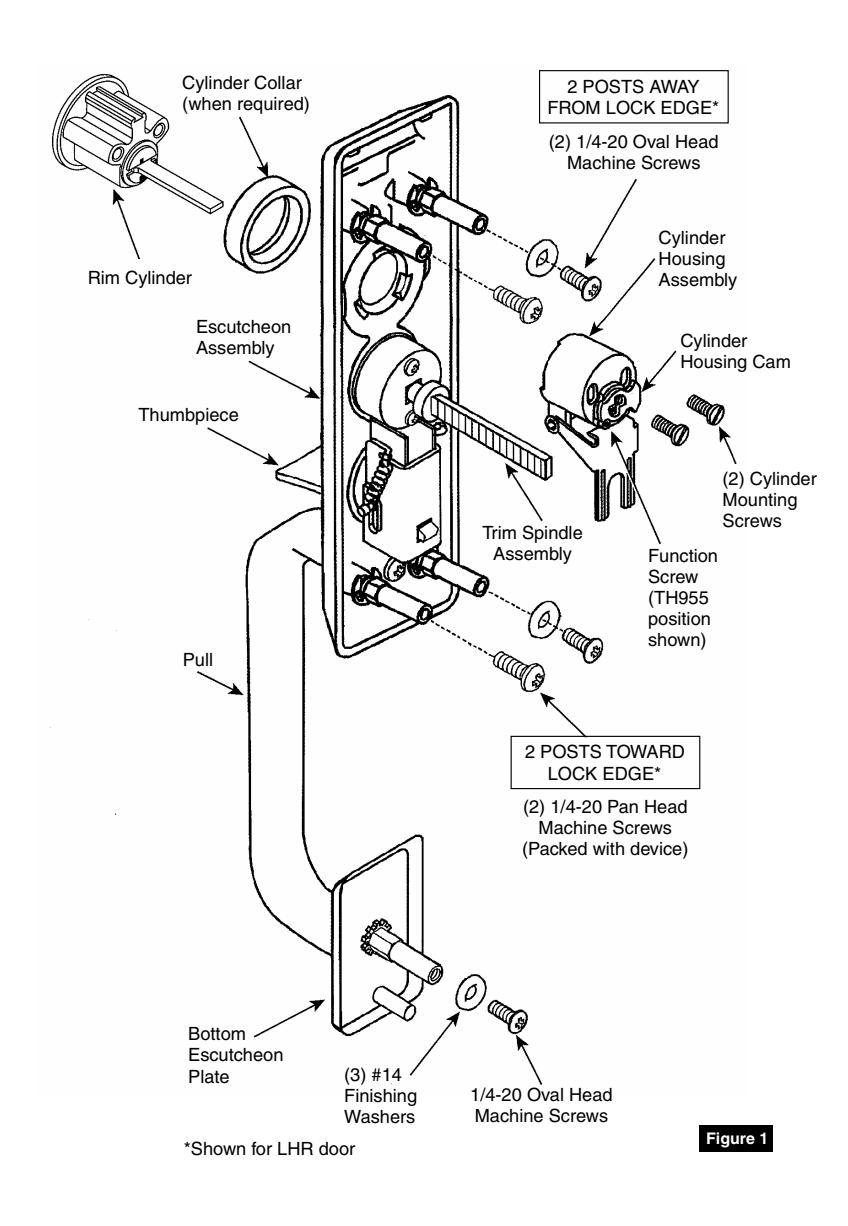
1. Check cylinder components.
NOTE: Cylinders longer than 1-1/8" (29) will require collars. (Figure 2)
- 2. When required, cut cylinder tailpiece. Correct length is 1/16" to 3/16" (2 to 5) beyond cylinder housing cam.
- 3. Assemble cylinder. Insert cylinder housing prongs into matching notches of escutcheon. Pass cylinder tailpiece through cylinder collar (when required) and slot in cylinder housing cam. Fasten cylinder using two (2) mounting screws.
- 4. Check cylinder action. Rotate cylinder tailpiece to cam clutch lever down. This depresses trim spindle assembly which disengages trim spindle from thumbpiece, putting trim in a free-wheeling, locked mode.
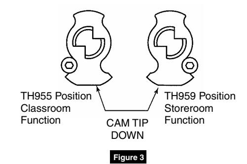
- 5. Determine trim function. TH955 (Classroom): Key locks/unlocks thumbpiece TH959 (Storeroom): Key locks/unlocks thumbpiece Key removable ONLY in locked position
- 6. To change trim function: Rotate cam tip to down position (locked mode). Move function screw as shown. (Figure 3)
|
Corbin Russwin
Cylinder Collar Chart |
|
|---|---|
| Cylinder Length | Collar |
| 1-1/8" (29mm) | None |
| 1-1/4" (32mm) | 654F07** |
| 1-1/2" (38) | 654F08** |
** Specify Finish

For ED5000 Series Exit Device
Installation Instructions

5 Installation
- 1. Assemble trim. (Figure 1)
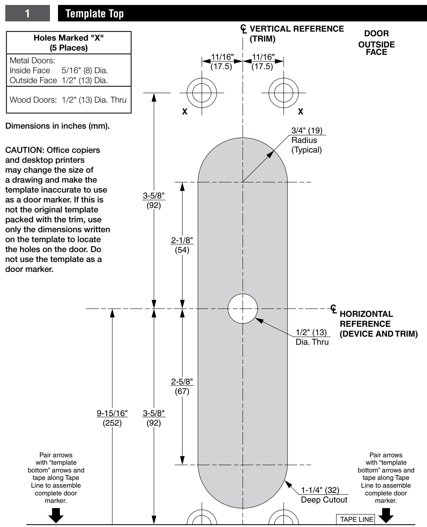
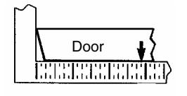
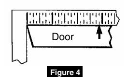
- 2. After marking door inside face for device location (Device Instructions), transfer "Vertical Reference Centerline" from inside to outside door face. (Figure 4)
- 3. Transfer "Horizontal Reference Centerline" from inside to outside door face.
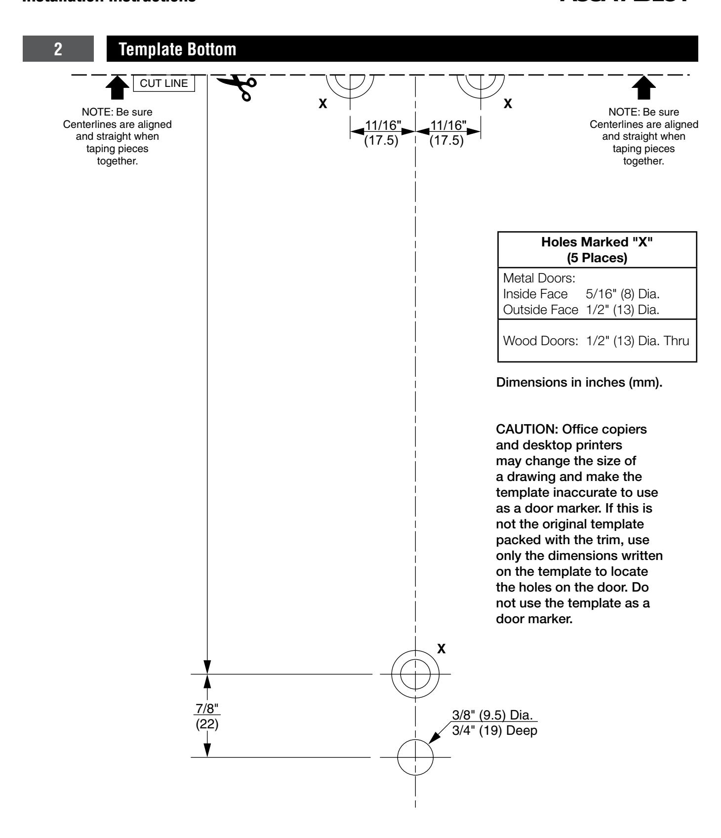
- 4. Align trim template and tape to outside door face. (pages 2 and 4)
- 5. Spot holes and prepare door for trim.
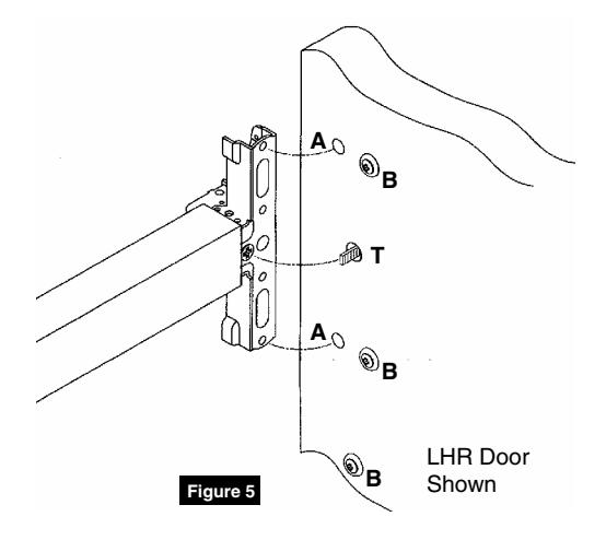
- 6. Mount trim to door through holes "B". Fasten, finger tight only, with three (3) screws and washers seating on door, as shown. (Figure 5) Bottom screw and washer engages lower post on pull.
NOTE:
- Device is bolted to trim using holes "A" (closest to door lock edge).
- Trim spindle "T" engages with vertical cross hole of cam slot.
- Screws and washers bolt trim to door using holes "B".
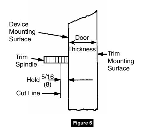
- 7. Cut trim spindle as shown. (Figure 6)
NOTE:
- Measure from device mounting surface (door face or shim surface).
- Trim must be unlocked (spindle fully extended).
- 8. Seat device so that trim spindle engages vertical cam slot, as shown. (Figure 5) Continue as shown in device instructions.

7

Corbin Russwin 225 Episcopal Road Berlin, CT 06037 Phone: 800-543-3658 Fax: 800-447-6714 corbinrusswin.com
Copyright © 2018 Corbin Russwin, Inc., an ASSA ABLOY Group company. All rights reserved. Reproduction in whole or in part without the express written permission of Corbin Russwin, Inc. is prohibited.