


TH910
Heavy Duty Thumbpiece Trim For use with ED5000 Series Exit Device
Metal, Wood or Composite Doors
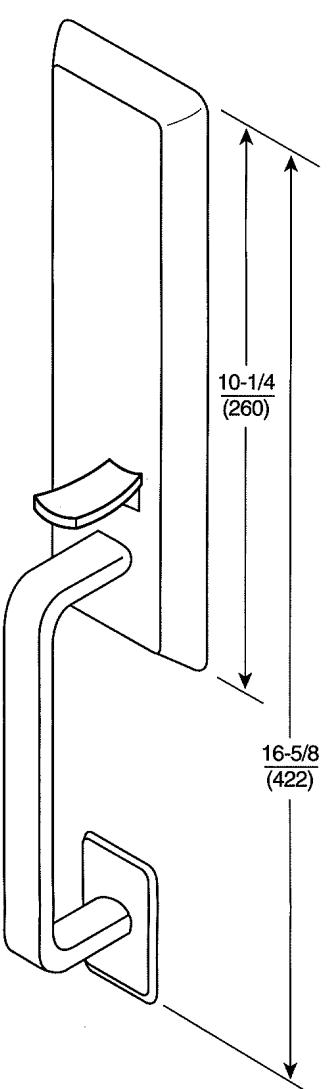
*Shown for LHR door
For installation assistance contact Corbin Russwin 1-800-543-3658 • techsupport.corbinrusswin@assaabloy.com
TH910 Heavy Duty Thumbpiece Trim
For ED5000 Series Exit Device
Installation Instructions

TH910 Heavy Duty Thumbpiece Trim
For ED5000 Series Exit Device
Installation Instructions

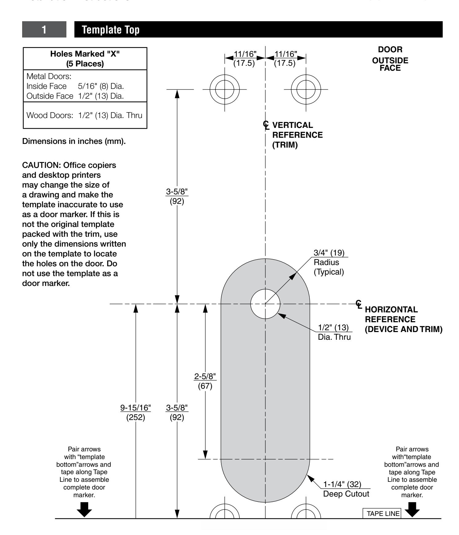
Template Bottom CUT LINE NOTE: Be sure NOTE: Be sure Centerlines are aligned Centerlines are aligned <u> 11/16"</u> and straight when and straight when taping pieces taping pieces together. together. Holes Marked "X" (5 Places) Metal Doors: Inside Face 5/16" (8) Dia. Outside Face 1/2" (13) Dia. Wood Doors: 1/2" (13) Dia. Thru Dimensions in inches (mm). CAUTION: Office copiers and desktop printers may change the size of a drawing and make the template inaccurate to use as a door marker. If this is not the original template packed with the trim, use only the dimensions written on the template to locate the holes on the door. Do not use the template as a door marker. 3/8" (9.5) Dia. 3/4" (19) Deep

3 Installation
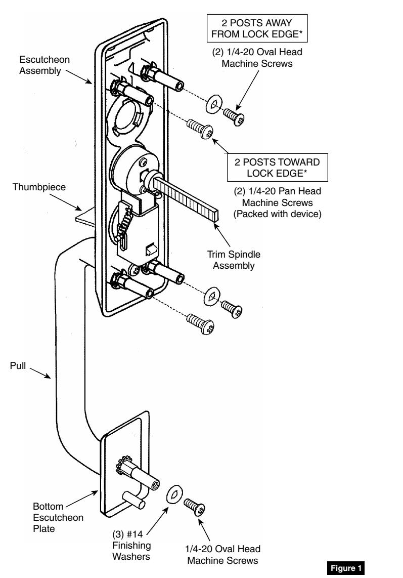
- 1. Check box contents. (Figure 1)
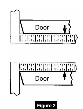
- 2. After marking door inside face for device location (Device Instructions), transfer "Vertical Reference Centerline" from inside to outside door face. (Figure 2)
- 3. Transfer "Horizontal Reference Centerline" from inside to outside door face.
- 4. Align trim template and tape to outside door face. (pages 2 and 3)
- 5. Spot holes and prepare door for trim.
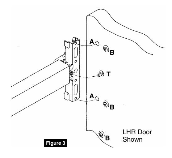
- 6. Mount trim to door through holes "B". Fasten, finger tight only, with three (3) screws and washers seating on door, as shown. (Figure 3) Bottom screw and washer engages lower post on pull.
NOTE:
- Device is bolted to trim using holes "A" (closest to door lock edge).
- Trim spindle engages with vertical cross hole of cam slot.
- Screws and washers bolt trim to door using holes "B".
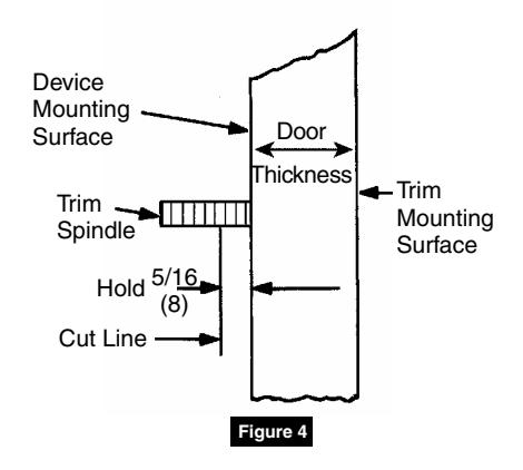
- 7. Cut trim spindle as shown. (Figure 4)
NOTE: Measure from device mounting surface (door face or shim surface).
8. Seat device so that trim spindle engages vertical cam slot, as shown. (Figure 3) Continue as shown in device instructions.
Corbin Russwin 225 Episcopal Road Berlin, CT 06037 Phone: 800-543-3658 Fax: 800-447-6714 corbinrusswin.com
For installation assistance contact Corbin Russwin 1-800-543-3658 • techsupport.corbinrusswin@assaabloy.com