


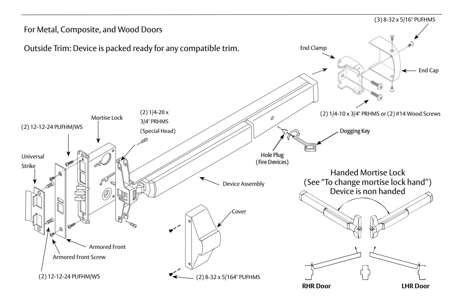
ED5600(A) Series
Mortise Exit Devices

This product can expose you to lead which is known to the state of California to cause cancer and birth defects or other reproductive harm. For more information go to www.P65warnings.ca.gov.
Dogging
Feature to hold bolts retracted and touchpad depressed, for push-pull door operation.
To Dog Device:
- 1. Insert dogging key.
- 2. Hold touchbar depressed.
- 3. Turn key 1/4 turn clockwise.
(Not a feature of fire labeled devices.)

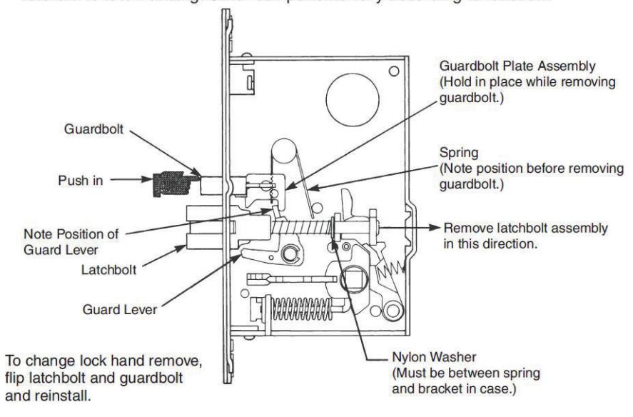
1 To Change Mortise Lock Hand
Shim Kit Option
650F951 Black Finish
Kit consists of Latch Head Shims (Device Cover seats on shim) and End Clamp Shims (End Cap seats on shim).
Each shim is 1/8" (3.2mm) thick more than two shim thicknesses 1/4" (6.4mm), require longer device mounting screws (not included).
Maintenance
- 1. Periodically remove covers and coat mechanisms with a silicone base lubricant. This is particularly required in corrosive environments for proper product function.
- 2. Check mounting fasteners periodically. Retighten if found loose. Apply screw locking compound (available at automotive part stores) or change part fasteners if screws continue to back out.

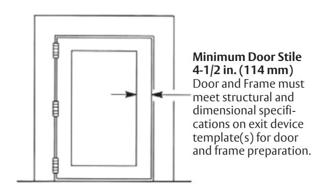
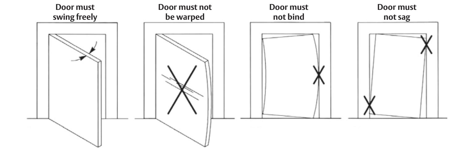
2 Pre-Installation
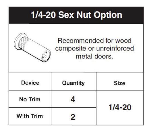
Unreinforced Door or Frames
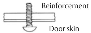
Doors and Frames with walls having a structural thickness (metal skin plus reinforcement, or solid hardwood) to engage less than (3) full screw threads, are considered unreinforced for hardware.
Unreinforced Doors: Use SNB (sex nuts and bolts).
Reinforced Door or Frame engages at least (3) screw threads.
Unreinforced Frames: Use Blind Rivet Nuts.

Note
Recommended fasteners for unreinforced openings are not necessarily supplied by Corbin Russwin, Inc.

3 Installation
a Mark Doo r
Locate and Mark Horizontal and Vertical Centerlines as shown.
LHR door shown. Preparation is typical for both door hands.
Note: Centerline of Lock (cutout) must match Horizontal Reference centerline.
b Prepare Door and Frame
Factory prepared cutouts with field drilled mounting holes are recommended. If door (lock) and frame (strike) have to be mortised in the field, do it before continuing (follow instructions on installation template).
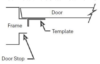
- 1. Locate and tape Trim Template to door. (See instructions packed with Trim.)
- 2. Seat plastic template on door and stop faces.
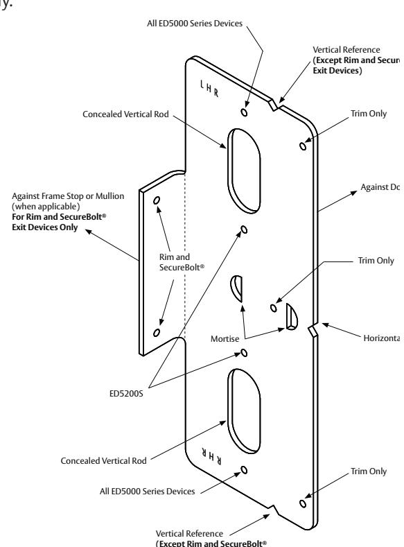
- 3 Locate plastic template, aligning VERTICAL REFERENCE and HORIZONTAL REFERENCE lines on door and template. Tape template to door face.
- (a) Slot 1/2" (12.7) diameter x 1" (25.4) on centers thru inside door face, using the two half circles on the plastic template for start and end of slot.
- (b) Device holes for 1/4-20 machine screws (metal reinforced doors only) or for 3/8" (9.5) diameter sex nuts and bolts. Metal reinforced doors only.
- 4. Insert lock into mortise, adjust front for door edge (beveled or flat).
- (2) Lock holes for 12-24 machine screws or for #12 wood screws.
NOTE: Lock base front has to be field tight-ened in place using two screws, each on lock case top and bottom.
- 5. Seat strike in frame cutout.
- (2) Strike holes for 12-24 machine screws or for #12 wood screws.
Exit Devices)
FM168 12/20

3 Installation (continued)
c Size Device
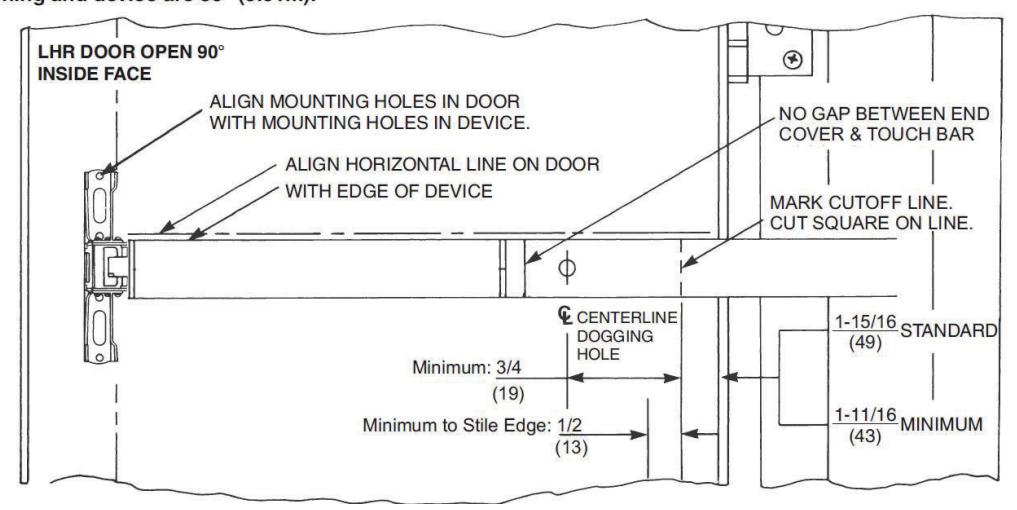
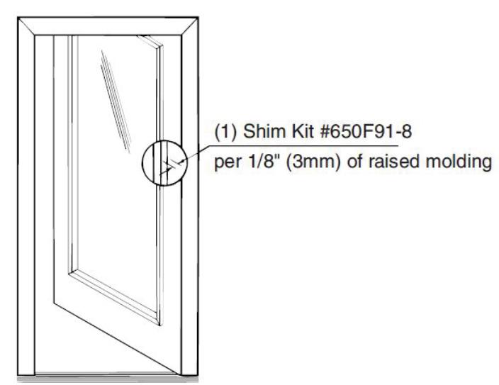
d Clear Raised Door Molding
Device must seat flush on door surface or on shims that keep it parallel to the door face. Two shim kits maximum for standard device in 1-3/4" (44) door. For thicker doors, consult the factory.

3 Installation (continued)
e Install Components
A. Install Lock
Lock in hand, depress guardbolt. Check that latchbolt is deadlocked. Check that latchbolt lever (and cylinder lever, hubs, and thumbpiece lever, if relevant) operate the lock freely. Insert Lock Body into door cavity. Fasten to door edge (2 PUFHM/WS)
Note: Make sure that door reinforcing clips or doorwalls support lock immovable (restricting rocking motion).

Fit over bolts and fasten to lock base front (2 PUFHMS). Check that bolts retract and extend freely.
C. Install Strike - Seat in place (lip bend away from opening) Fasten to frame (2 PUFHM/WS).
D. Install Trim - Follow instructions packed with trim.
E. Install Device
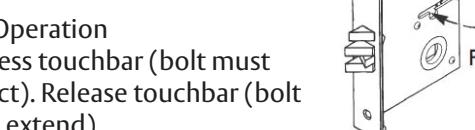
Seat Bar in place (Device finger must engage latchbolt lever, thru slot in lock case/cover, as shown in Detail 1). Fasten Device Head (2 PRHMS or SNB). Set Bar level. Locate End Clamp holes. Prepare End Clamp mounting holes. Fasten End Clamp in place. (2 #1/4-20 PRHMS or 3/8" (9.5) Dia. SNB).

1. Depress touchbar (bolt must retract). Release touchbar (bolt must extend).
2. Actuate trim (bolt must retract). Release trim actuator (bolt must extend).
- 3. (NOT FOR FIRE DEVICES) Depress touchbar, turn dogging key clock wise (bar must remain depressed, bolt must remain retracted). Turn dogging key counter clockwise (bar and bolt must return to extended position).
- 4. Close door. Latchbolt should fully engage into strike cavity, guardbolt should retract over strike ramp. Door should not rattle.
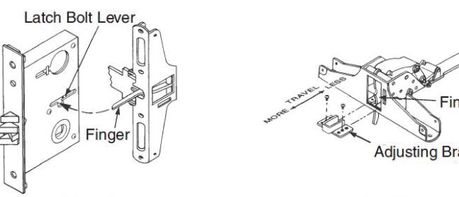
NOTE: When resulting operation is faulty, check first for visible binding or interference. If there is no apparent reason for the fault, remove item from the door and recheck its operation before assuming that it is defective. If latchbolt travel is not adequate, adjust device finger as shown on Detail 2.
G. Tighten all Mounting Screws.
5600(A) Series
Mortise Exit Devices
Installation Instructions

3 Installation (continued)
f Install Head Cover and End Cap
Use (2) 8-32 PFHMS for Cover and (3) 8-32 PFHMS for End Cap.


Corbin Russwin, Inc. 225 Episcopal Road Berlin, CT 06037 USA Phone: 800-543-3658 Fax: 800-447-6714 www.corbinrusswin.com