Installation Instructions
ED4400, ED4400M & ED4400MA Series Surface Vertical Rod Exit Devices

ASSA ABLOY
In U.S.: Corbin Russwin, Inc. 225 Episcopal Road Berlin, CT 06037 USA www.corbinrusswin.com
In Canada: ASSA ABLOY Door Security Solutions Canada 160 Four Valley Drive Vaughan, Ontario, Canada L4K4T9 www.assaabloy.ca
Technical Product Support: Phone: 888-607-5703

ASSA ABLOY
To Change Hands
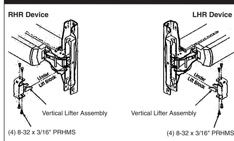
Remove (4) Screws and Vertical Lifter Assembly. Rotate device to opposite hand (180 degrees). Insert Lifter Assembly and reinstall screws.
Note: Lifter must fit under lift block as shown.
1/4-20 Sex Nut Option
| Device | Quantity | Size |
|---|---|---|
| No Trim | 8 | 1/4-20 |
| With Trim | 6 |
Rod Extension Options
Maintenance
- Periodically remove covers and coat mechanisms with a silicone base lubricant. This is particularly required in corrosive environments for proper product function.
- Check mounting fasteners periodically. Retighten if found loose. Apply screw locking compound (available at automotive part stores) or change part fasteners if screws continue to back out.
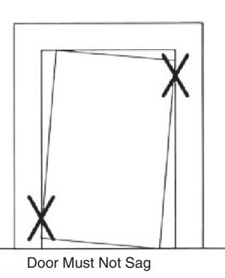
- 3. Periodic checks (and adjustments) of strikes are required to compensate for changes in the opening (e.g. door sagging).
Shim Kit Option
650F90-8 Black Finish
Kit consists of Device Head Shim (Device Cover seats on shim), End Clamp Shim (End Cap seats on shim), Top and Bottom Latch Shims (Bolt Case Mounting Plates seat on shim), and (2) Rod Guide Shims.
Each shim is 1/8" (3.2mm) thick.
More than two shim kits require longer device mounting screws (not included).
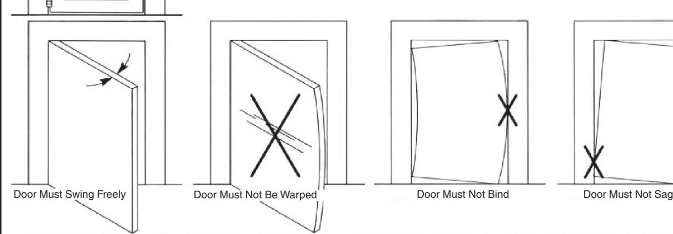
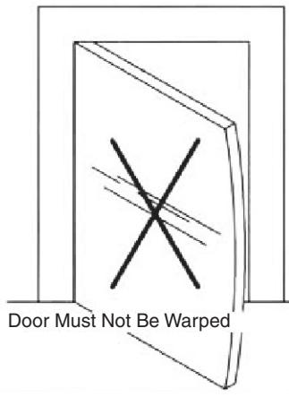
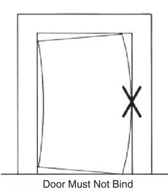
Check Before Starting

ASSA ABLOY
ED4400
Minimum Door Stile: 2" (50mm)
ED4400M & ED4400MA
Minimum Door Stile: 3-1/2" (89mm)
Door and frame must meet structural and dimensional specifications on exit device template(s) for door and frame preparation.
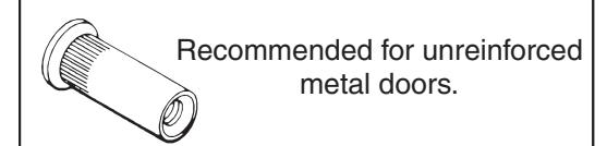
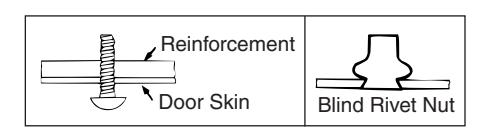
Unreinforced Doors or Frames
Doors and Frames with walls having a structural thickness (metal skin plus reinforcement) to engage less than (3) full screw threads are considered unreinforced.
Unreinforced Doors: Use SNB (sex nuts and bolts).
Unreinforced Frames: Use Blind Rivet Nuts.
Recommended fasteners for unreinforced openings are not necessarily supplied by Corbin Russwin.
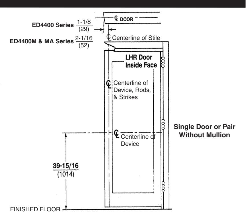
1. Mark Door
Locate and Mark Horizontal and Vertical Centerlines as shown.
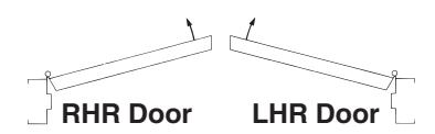
LHR door shown.
Preparation is typical for both door hands.
Caution: If device is mounted higher or lower than shown, rod length must change. Lengthen or cut top and bottom rods as shown on Step 7.
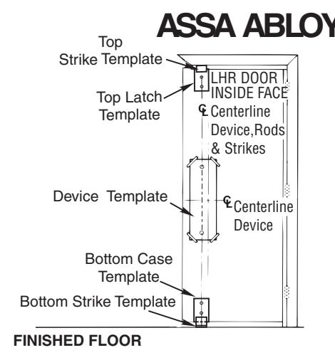
2. Prepare Door, Frame, & Sill

- A. Locate "Device Template" aligning VERTICAL and HORIZONTAL DEVICE CENTERLINES on door and template. Tape template to door face.
- B. Locate Top Latch/Strike, Bottom Case, and Bottom Strike templates, aligned on centerline of Device, Rods and Strikes on door. Tape templates in place.
- C. Locate and tape Trim Template to door (See instructions packed with Trim).
- D. Mark and prepare holes:
Device and Bolt Case Plates:
Each (2) 1/4-20 Machine Screws OR (2) 3/8" (10) Dia. Sex Nuts & Bolts
Top Strike: (2) 10-24 Machine Screws
Bottom Strike: 5/8" (16) Dia. x 3/4" (19) Deep Hole
3. Clear Raised Door Molding
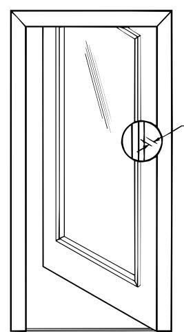
Device must seat flush on door surface or on shims that keep it parallel to door face.
(1) Shim Kit #650F90-8 needed to clear each 1/8" (3mm) of raised molding
Longer mounting screws needed when more than (2) shim kits are used. See Shim Kit Option on page 2.
4. Size Device
Device must be field cut to size unless standard opening and device are 36" (0.91m) or 48" (1.22m).
LHR DOOR (OPEN) INSIDE FACE
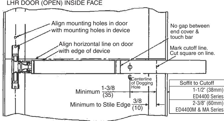
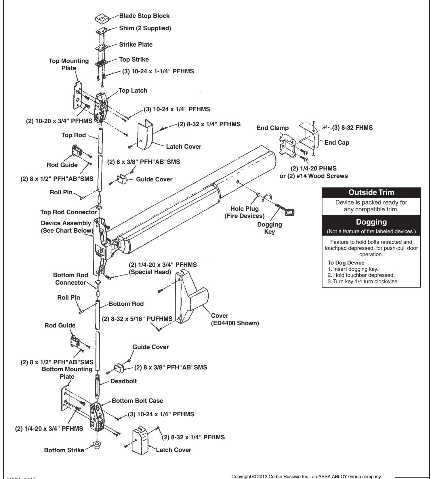
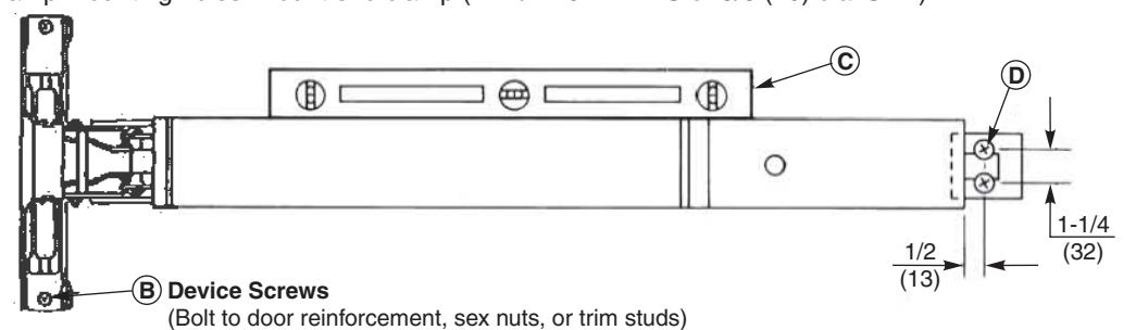
5. Install Device
- A. Mount trim (Follow Instructions Packed with Trim).
- B. Seat bar in place. (Projecting C-Cam boss must penetrate into door hole.) Fasten device head (2 PRHMS or SNB).
- C. Set bar level. Locate end clamp holes.
- D. Prepare end clamp mounting holes. Mount end clamp (2 #1/4-20 PRHMS or 3/8 (10) dia. SNB).
-
E.
Check slide action (Slide travel = 9//16" (14).
- 1. Depress touchbar (slide should move up). Release touchbar (slide should fall back to original rest position).
- 2. Activate trim (slide should move up). Release trim activator (slide should fall back to rest position).
- 3. (NOT FOR FIRE DEVICES) Depress touchbar, turn dogging key clockwise (bar must remain depressed, slide
must remain in up position). Turn dogging key counterclockwise (bar should extend, slide should fall back to rest position). NOTE: When resulting operation is faulty, check first for visible binding or interference. If there is no apparent reason for the fault, remove item from the door and recheck its operation before assuming that it is defective.
F. Tighten all mounting screws.
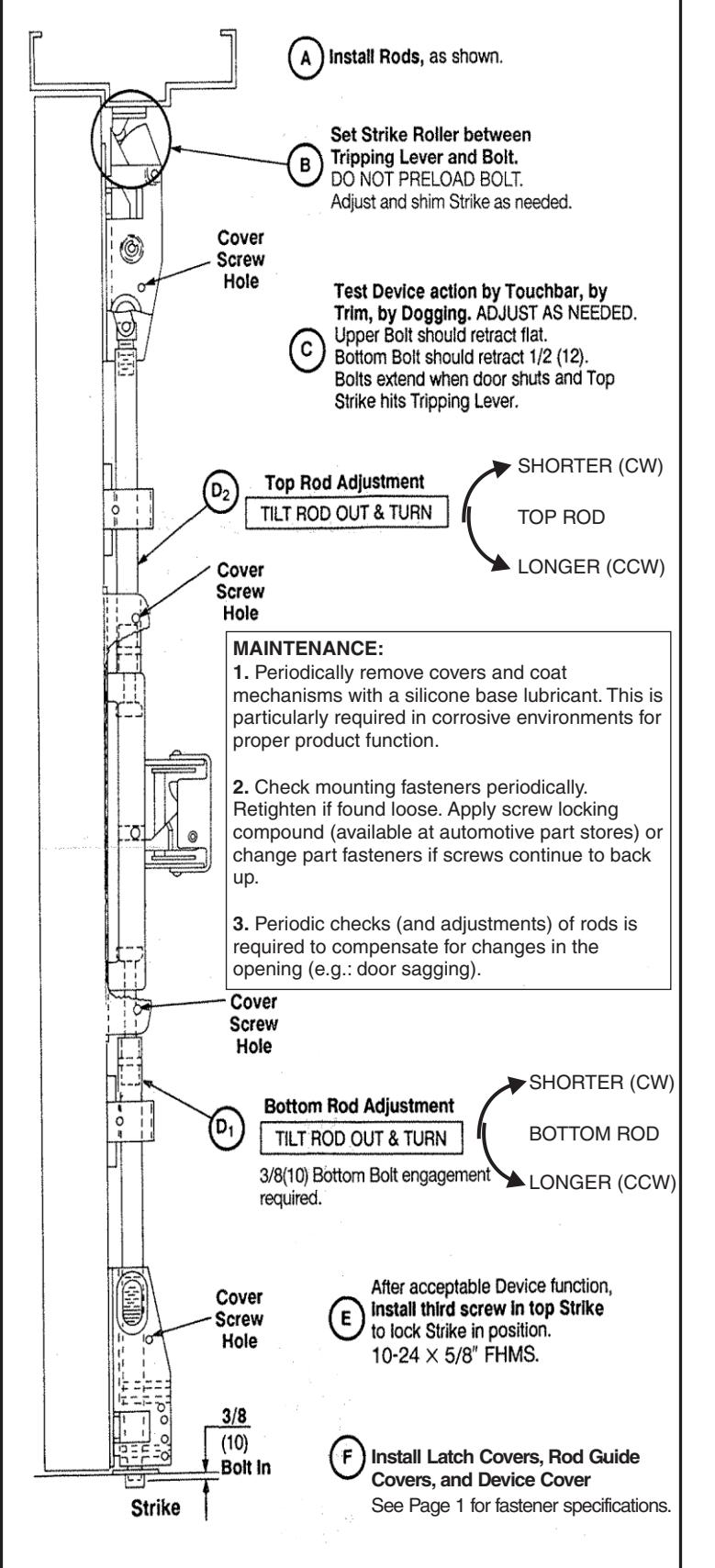
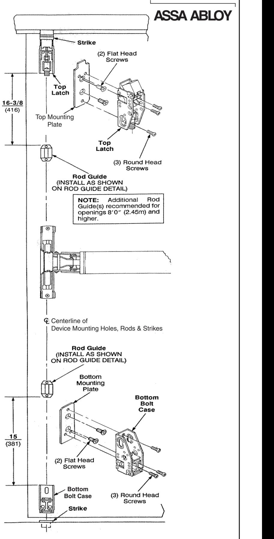
6. Set Latches, Strikes & Guides

Top Strike Detail
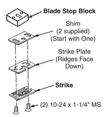
NOTE: Reserve third screw for Step 8 E .
Blade Stop Mount shown. When Formed Stop is used, omit Blade Stop Block and mount Strike with 5/8" long screws (in 791 Strike Pack).
Rod Guide Detail (Typical 2 Places)
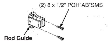
- Locate Rod Guide as dimensioned. Spot (2) mounting holes.
- Prepare holes. Metal Door: .140 (3.50) dia. inside face
- Mount Guide.
Bottom Strike Detail
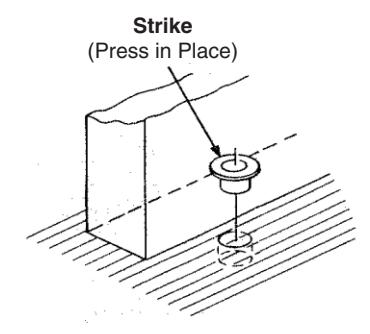
NOTE: Bottom Bolt will retract to 1/8" (3) above Floor Strike. Floor coverings in the door path must be laid accordingly.
All dimensions are in inches (mm) unless otherwise noted.
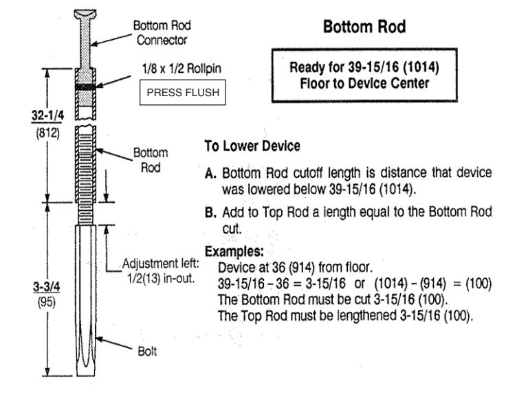
7. Prepare Rods
8. Complete Installation
Corbin 78 Russwin 78
ASSA ABLOY
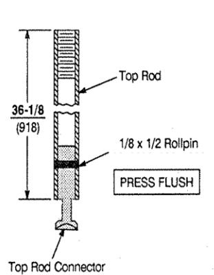
Top Rod Ready for 84 (2134) Openings
Openings Under 84 (2134)
For Top Rod cutoff length, deduct OPENING HEIGHT from 84 (2134).
Example:
Opening = 80 (2032)
84 - 80 = 4 or (2134) - (2032) = (102)Top Rod must be cut 4 (102).
Openings Over 84 (2134)
For Top Rod additional length, deduct 84 (2134) from OPENING HEIGHT.
Example: Opening = 99 (2515) 99 - 84 = 15 or (2515) - (2134) = (381) Top Rod must be lengthened 15 (381).
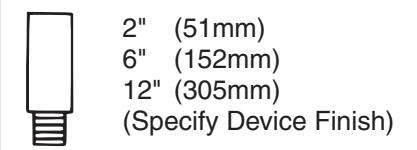
To Lengthen Rods
- Use Rod Extension(s) to extend Rod to length needed or longer (2", 6", or 12" Rod Extensions available).
- Cut excess length from end of rod with pin hole.
- Apply screw locking compound* to Rod Extension(s) male threads. Thread Extension(s) until seated tight over Rod.
(*) Available at automotive parts store.
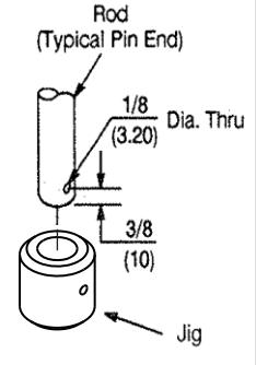
To Cut Rods
- Cut from end with pin hole. NEVER CUT THREADED END.
- Press Jig until it bottoms over Rod.
- Drill 1/8" (3) dia. hole thru, 3/8" (10) from end of Rod.