


Installation Instructions

Exit Device Shim Kits Yale 1800, 2100 & 7000 Series and Corbin Russwin ED2000 Series
Shim Locations
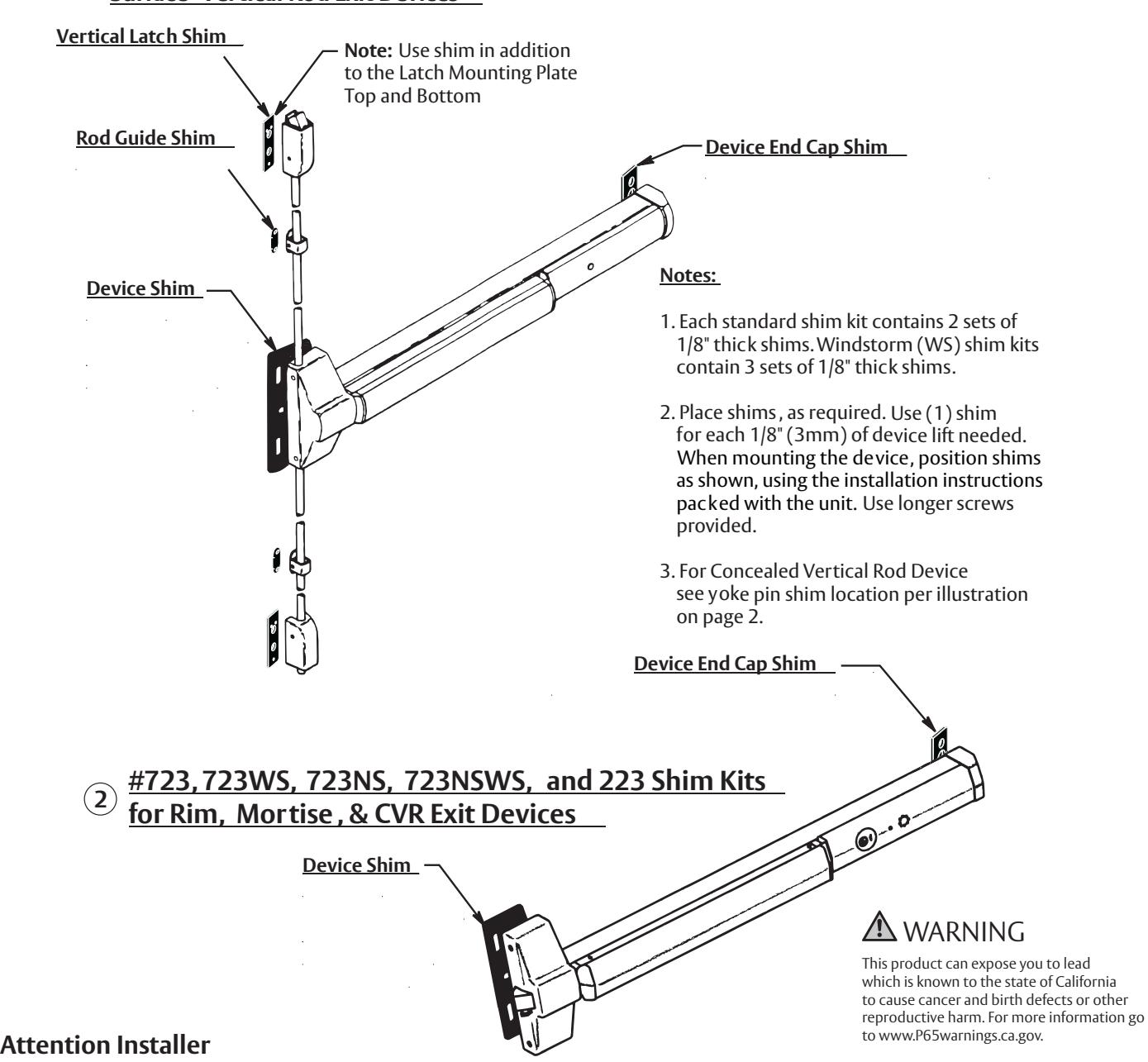
#724, 724WS, 724NS, and 224 Shim Kits for Surface Vertical Rod Exit Devices 1
Any retrofit or other field modification to a fire rated opening can potentially impact the fire rating of the opening, and Assa Abloy Locks & Hardware makes no representations or warranties concerning what such impact may be in any specific situation. When retrofitting any portion of an existing fire rated opening, or specifying and installing a new fire-rated opening, please consult with a code specialist or local code official (Authority Having Jurisdiction) to ensure compliance with all applicable codes and ratings.
Spindle Assembly
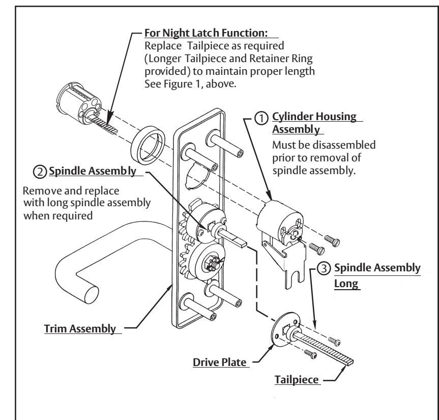
CA UTION:
When removing the spindle assembly from the trim, keep the clutch spring and screws, they are needed for reassembly. When finished, check the lock and unlock function before mounting. Follow detail Figure 1 for sizing the tailpiece to the door thickness.
For Thumbpiece Applications:
Thumbpiece applications follow the same procedure as above, but the original smaller drive plate must be used with the new tailpiece included in the kit. To do this remove the cylinder housing assembly and the original spindle assembly from the trim (steps 1 & 2 to left). Remo ve the retaining ring from both spindle assemblies, switch the tailpieces and reassemble (longer tail-piece to the smaller drive plate) with a retaining ring. Reattach to trim using clutch spring and screws; then reassemble the cylinder housing with the cylinder.
540F or 440F Trim Applications:
F or 540F or 440F Trim remove roll pin from Tailpiece assembly (keep pin), remove Tailpiece and replace with optional Tailpiece supplied. Use initial roll pin to reassemble. Size to fit, see Figure 1, above.
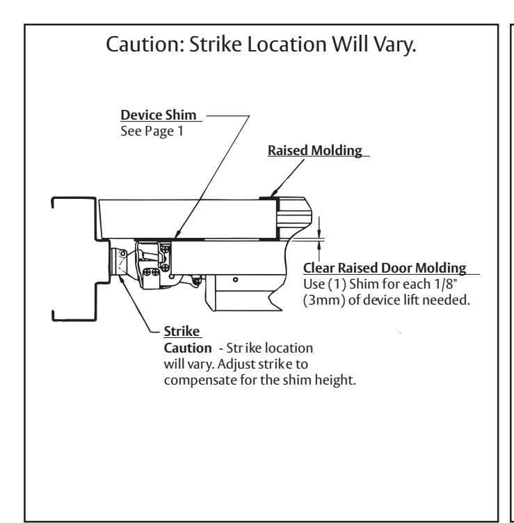
Strike
Caution - Strike location will vary. Adjust strike to compensate for the shim height.
Clear Raised Door Molding
Use (1) Shim for each 1/8" (3mm) of device lift needed.