


← Corbin
DL4100 Series
Auxiliary Deadlock
Installation Instructions

Auxiliary Deadlock
- 1 Confirm lockset is the correct bevel for the door. If not, loosen the screws fastening front to case. Rotate front to proper bevel and retighten screws.
- 2 Prepare door and frame using template T31180.
- 3 Mount lock using two combination screws.
- Place cylinder thru cylinder collar and screw into lock. (See Figure 1)
NOTES:
- Pull key slightly out of cylinder to help thread into lockbody.
- Cylinder must be oriented correctly. (See Figure 2)

4113, 4117, 4160 FUNCTIONS
- 5 Tighten appropriate set screw into cylinder.
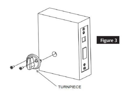
- 6 Attach turn-piece as shown. (See Figure 3)
For 4122 function, turn-piece must be inverted. (See Figure 4) For ergonomic turn-piece, see alternative instructions on page two.

- Attach outside front using two 1/4" machine screws. (See Figure 1)
- Install strike and strike box (optional) using two combination screws. (See Figure 5)

OUTSIDE FACE OF DOOR
INSIDE FACE OF


Ergonomic Turn-Piece Auxiliary Deadlock, continued
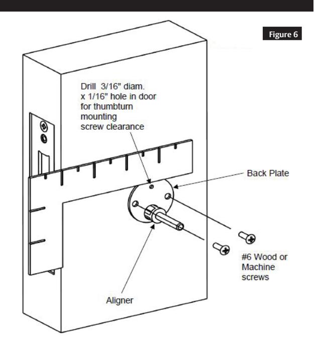
- 1. After installing the lockbody, insert the alignment tool.
- 2. Place back plate over the alignment tool and use a carpenter's square to orient. (See Figure 6)
- 3. Mark three screw holes and remove backplate, alignment tool, cylinder (if applicable) and lockbody.
- 4. Drill two pilot holes for #6 screws (Wood = 3/32" holes, Metal = Drill/Tap for #6-32 machine screws).
- 5. Drill 3/16" clearance hole, 1/16" deep for upper mounting screw.
- 6. Re-install lockbody and cylinder. (See steps 3-5 on page 1)
- 7. Install back plate using two #6 mounting screws. (See Figure 6)
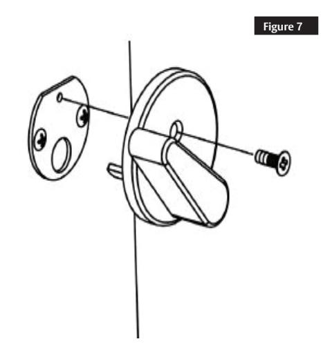
- 8. Install turn-piece using one #6 machine screw. (See Figure 7)
WARNING
This product can expose you to lead which is known to the state of California to cause cancer and birth defects or other reproductive harm. For more information go to www.P65warnings.ca.gov.
For installation assistance contact Corbin Russwin 1-800-543-3658 • techsupport.corbinrusswin@assaabloy.com