


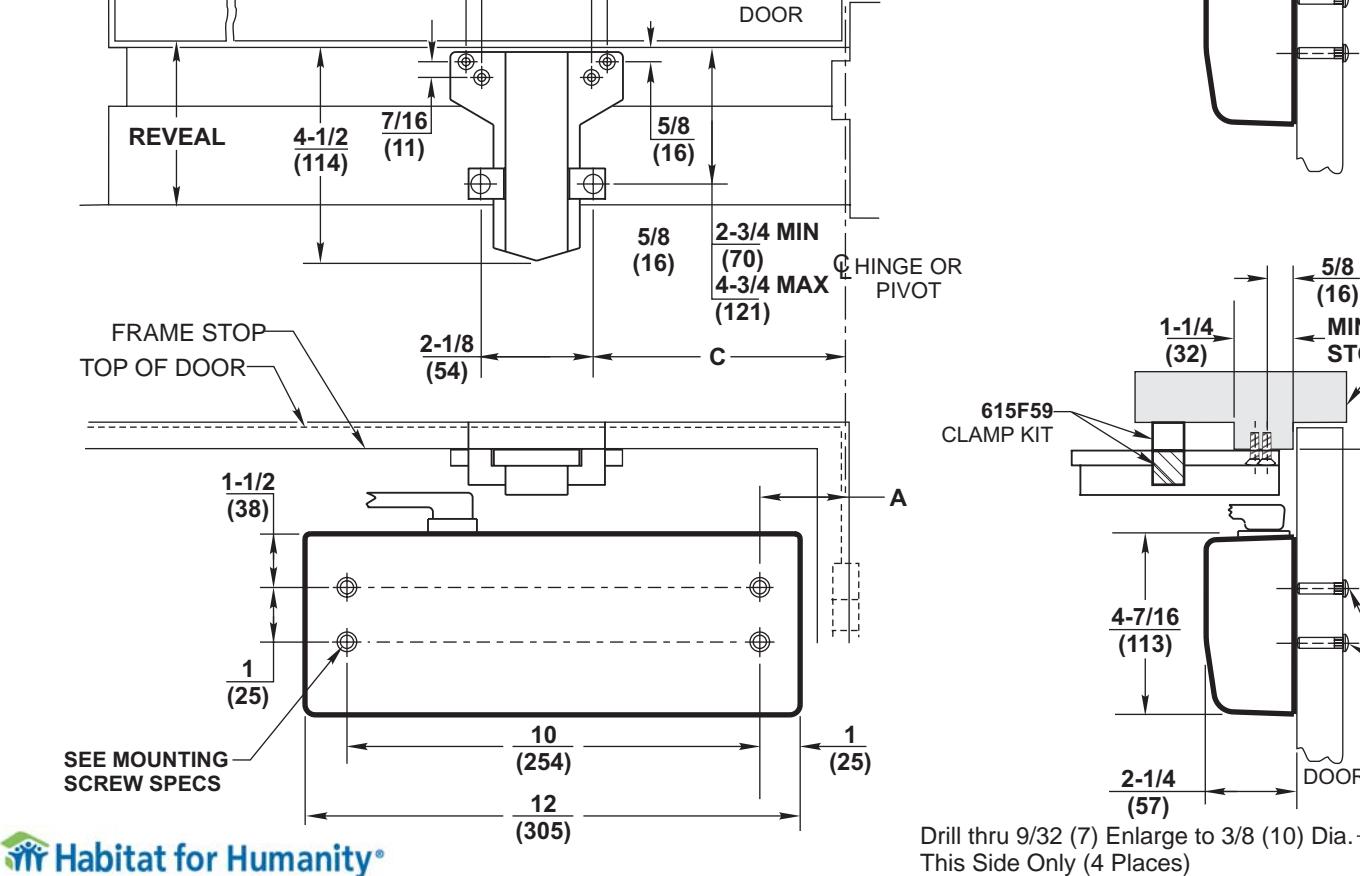
MOUNTING INFORMATION
Sex nuts or through bolts are required for wood and plastic covered composite doors, and any type of door without reinforcements and recommended for wood core and metal clad (Kalamein) type doors.
RH SHOWN LH OPPOSITE
MOUNTING SCREW SPECIFICATIONS ARM AND QUIK-INSTALL™ BRACKET #12-14 self-drilling screw. 1/8 (3) diameter pilot hole Sex nuts, furnished required for Wood when ordered Applications. 1-21/32 9/16 DIA. 3/8 (42)(10)(14)1/4-20 THREAD -
ТП
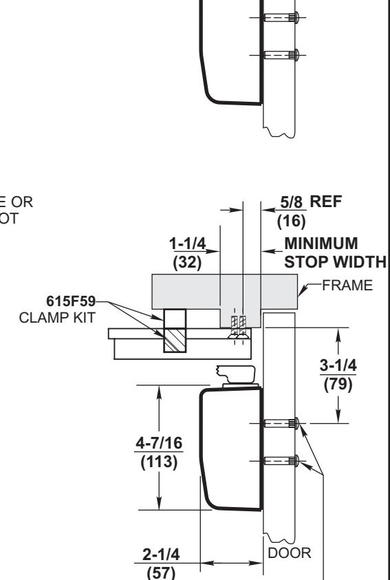
615F59-
CLAMP KIT
(CLAMP ONLY)
Closer To Be Installed In A True Horizontal CAUTION: Closer to be installed in A that the control of the Proper Closer Performance.
| DOORS 28" TO 32" | |||||||
|---|---|---|---|---|---|---|---|
| Opening | 615F52 NHO ARM (A11) | ||||||
| 615F51 HO ARM (A12) | |||||||
|
HOLD
OPEN |
DEAD
STOP |
Dim. A | Dim. B | Dim. C | |||
| 85° | 90° | 5-3/4 (146) | 9-3/4 (248) | 10-1/16 (256) | |||
| 90° | 95° | 5-1/4 (133) | 9-1/4 (235) | 9-9/16 (243) | |||
| 95° | 100° | 4-3/4 (121) | 8-3/4 (222) | 9-1/16 (230) | |||
| 100° | 105° | 4-3/8 (111) | 8-3/8 (213) | 8-11/16 (221) | |||
| 105° | 110° | 4 (102) | 8 (203) | 8-5/16 (211) | |||
| 110° | 115° | 3-3/4 (95) | 7-3/4 (197) | 8-1/16 (205) | |||
| NOTES | |||||||
| DOORS 33" TO 41" | |||||||||
|---|---|---|---|---|---|---|---|---|---|
| 615F54 NHO ARM (A11) | |||||||||
| 615F53 HO ARM (À12) | |||||||||
| Dim. A | Dim. B | Dim. C | |||||||
| 8-1/8 (206) | 11-7/8 (302) | 12-3/16 (310) | |||||||
| 7-5/8 (194) | 11-3/8 (289) | 11-11/16 (297) | |||||||
| 7-1/8 (181) | 10-7/8 (276) | 11-3/16 (284) | |||||||
| 6-5/8 (168) | 10-3/8 (264) | 10-11/16 (271) | |||||||
| 6-1/4 (159) | 10 (254) | 10-5/16 (262) | |||||||
| 6 (152) | 9-3/4 (248) | 10-1/16 (256) | |||||||
| - 1 | DOORS 42" TO 48" | |||||||||
|---|---|---|---|---|---|---|---|---|---|---|
| - | 615F56 NHO ARM (A11) | |||||||||
| 615F55 HO ARM (À12) | ||||||||||
| Din | 1. A | Dim. B | Dim. C | |||||||
| ) | 10-1/4 | (260) | 14-1/4 | (362) | 14-9/16 | (370) | ||||
| ) | 9-3/4 | (248) | 13-3/4 | (349) | 14-1/16 | (357) | ||||
| ) | 9-1/8 | (232) | 13-1/8 | (333) | 13-7/16 | (341) | ||||
| ) | 8-1/2 | (216) | 12-1/2 | (318) | 12-13/16 | (325) | ||||
| ) | 8 | 12-5/16 | ||||||||
| ) | 7-5/8 | (194) | 11-5/8 | (295) | 11-15/16 | (303) | ||||
NOTES:
- 1. Dimensions given in inches and (mm).
- 2. Minimum Top Rail: 5 (127).
- 3. Frame Reveals 1-7/8 (48) to 4-5/8 (117)4
- 4. These dimensions apply to the centerline of hinge/pivot for butt hinges or offset pivots.
- 5. A12 arms cannot be used on fire doors.
2-3/4
(70)
(51)
3/8
(10)
RESPONSIBILITY
Door and Frame Manufacturers are responsible for providing adequate construction or reinforcements for proper installation of hardware shown. All architectural builders hardware must be installed on properly reinforced doors and frames, regardless of the type, material, or method of construction.
DC8210 Series x A11/A12 x 615F59
A11 or A12 Push Side Parallel Arm Mounted Surface Door Closer with 615F59 Clamp Kit
Corbin 7
ASSA ABLOY
www.corbinrusswin.com
Do Not Scale Drawing Dr. Date 04-08 Template Number T31062