|
P
i f F t t re pa ra on or as en er s |
||
|---|---|---|
|
F
t as en er s |
D
r F oo r o ra m e |
S
D ri l l- i ze s |
|
S
f- S el D ri l l i n g cr ew |
A
l i um nu m M al et or |
N
d ri l l i d o re qu re |
|
W
d oo ( N ) ot se e e |
/
( ) 3 1 6" 4 .3 0 m m P i l h ol i d ot e re qu re |
|
|
/
4" h i 1 - 2 0 m ac ne s cr ew |
M
al et |
D
ri l l ( 1" d i ) : # 7 0 .2 0 a. T 1 / 4" - 2 0 a p: |
|
S
l nd b ol ut t ee ve n s a s |
H
ol l ow M al et |
/
2" ( ) h gh 9 3 7 t m m ro u ; 3 / 8" ( 9 ) d r f .5 m m oo ac e si cl t t o p po e o os er |
|
A
l i um nu m or W d D oo oo rs |
/
8" ( ) h gh 3 9 .5 t m m ro u |
|
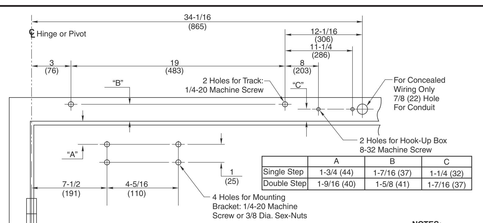
Note: MUST Wood doors/frames have pilot hole when using Self-Drilling Screws.
NOTES:
From centerline of pivot point to end of track and hook-up box is 35-3/16 (894)
Right hand door shown
Do not scale drawing
Dimensions are given in inches (mm)
Minimum ceiling clearance for unit is 2-1/8" (54mm)
Maximum door opening is 105°
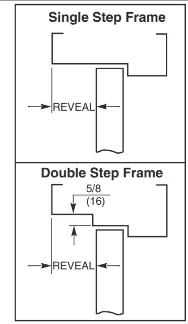
Charted dimensions measured from door rabbet.
Hollow-metal doors require channel or box-type reinforcement when thru-bolt mount is specified. Minimum thickness recommended for reinforcements in hollow-metal doors and frames: .1046 (2.66 mm) unless otherwise noted.
RESPONSIBILITY
DOOR AND FRAME MANUFACTURERS ARE RESPONSIBLE FOR PROVIDING ADEQUATE CONSTRUCTION OR REINFORCEMENTS FOR PROPER INSTALLATION OF HARDWARE SHOWN. ALL ARCHITECTURAL BUILDERS HARDWARE MUST BE INSTALLED ON PROPERLY REINFORCED DOORS AND FRAMES, REGARDLESS OF TYPE, MATERIAL, OR METHOD OF CONSTRUCTION.
1 DC62930 ETD-DE Series Master Unit
For Installations with a Double Egress Frame Combination Door Closer-Holder with Single Point Hold Open Hinge (Pull) Side Mounting for Hinge Side Frame Reveals 1/8" to 3" (3 to 76 mm)