


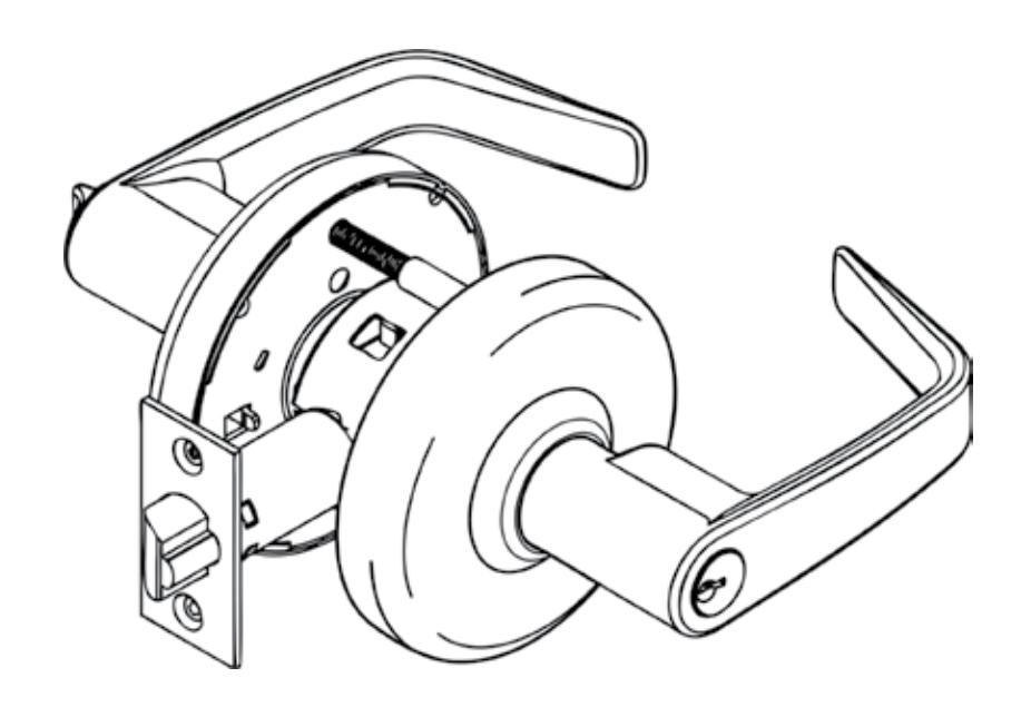
CL3500 Series
ANSI/BHMA Grade 1
Key-In-Lever
Cylindrical Lockset

This product can expose you to lead which is known to the state of California to cause cancer and birth defects or other reproductive harm. For more information go to www.P65warnings.ca.gov.

CL3500 Series
Cylindrical Lockset
Installation Instructions

| Table of Contents | |
|---|---|
| Lever Removal Installation 8 | |
|
Standard Installation 3
Install Latchbolt, Lockbody and Inside Trim 3 Door and Frame Preparation 4 Mark Door 4 Drill Door 4 Install Strike 4 Optional Installations 5 For CL3580 and CL3581 Function Only 5 Cylinder Installations 5 Interchangeable Core Installation 5 Interchangeable Core Removal 6 Standard Cylinder Installation 7 Conversion Kit 7 |
Attention Installer
Please read these instructions carefully to prevent missing important steps.
Notes
- Improper installation may result in damage to lock and void factory warranty.
- Other product brand names may be trademarks or registered trademarks of their respective owners and are mentioned for reference only.

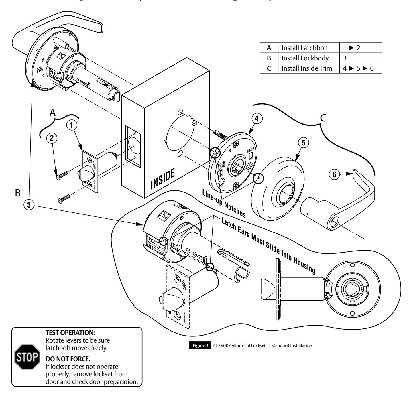
1 Standard Installation
a Install Latchbolt, Lockbody and Inside Trim
Important
The accuracy of door preparation is critical for proper functioning and security of lever handle lock. Misalignment can cause premature wear and lessening of security.
2 Door and Frame Preparation
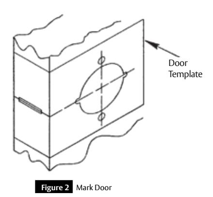
a Mark Door
Locate and mark horizontal center line at desired height above floor. Fold template over edge of door, centering on horizontal line. Mark centers of holes at proper backset. Mark both sides of the door.
Note
Be sure to verify backset before marking and drilling door.
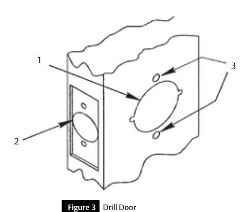
b Drill Door
- 1. 2-1/8" (54mm) hole through door. Cut ANSI tab notches as shown on template (except CL3550 and CL3570).
- 2. Drill 1" (25mm) hole in edge of door. Cut out for latch front 5/32" (4mm) deep. 1-1/8" (29mm) wide x 2-1/4" (57mm) high. Check latch unit for proper width front and square or round corners (except CL3550 and CL3570).
- 3. Drill two (2) 11/32" (8mm) diameter holes through door for all functions.
Caution
To avoid splintering wood doors, drill holes from both sides.
For installation assistance contact Corbin Russwin
c Install Strike
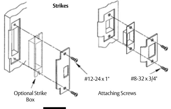
4
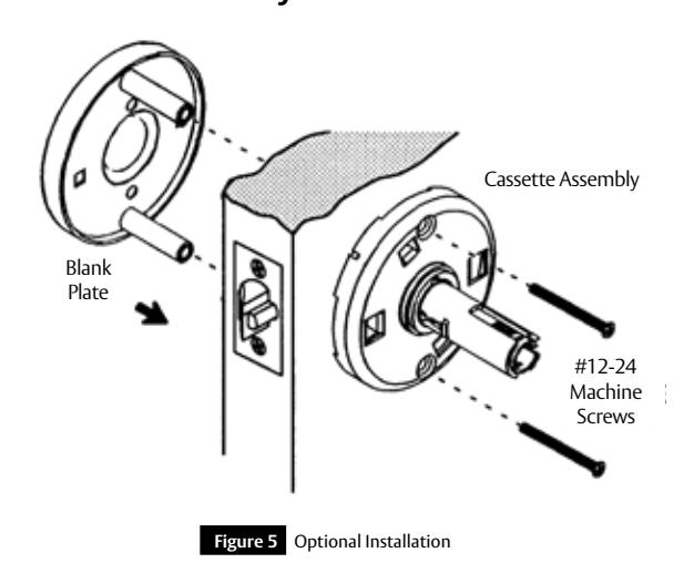
3 Optional Installations
a For CL3580 and CL3581 Function Only
4 Cylinder Installations
a Interchangeable Core Installation
To install interchangeable core (with lever already installed on lock), see Figure 6:
• Install tailpiece.
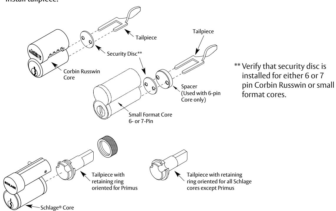
Figure 6 Tailpiece Installation
4 Cylinder Installations (cont.)
a Interchangeable Core Installation (cont.)
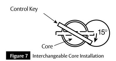
• Insert key marked CONTROL and turn clockwise approximately 15°. See Figure 7.
- Insert core into lever and return key to its original horizontal position locking core in place. See Figure 8.
- Withdraw key. Test lockset for correct function with operating key.
- Control key has no further use in lockset installation and must be safeguarded for return to security personnel when installation is complete.
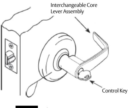
Figure 8 Locking Core
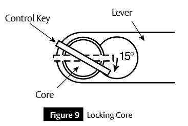
b Interchangeable Core Removal
To remove interchangeable core:
- Insert key marked CONTROL and turn clockwise approximately 15°. See Figure 9.
- Pull core and tailpiece completely out of lever.
FM237 03/19
6
ASSA ABLOY
Cylinder Installations (cont.)
Standard Cylinder Installation
Before installing cylinders, be sure lock is unlocked and cylinder tailpiece is aligned in same direction as cylinder bible.
To install standard cylinder (Figure 10):
- Slide cylinder all the way into lever.
- 6-pin cylinder: fold retainer at hinge and press fit retainer halves together.
- 7-pin cylinder: break retainer at hinge and discard spacer section. Remove black cylinder spacer from inside of chassis rollback for clearance.
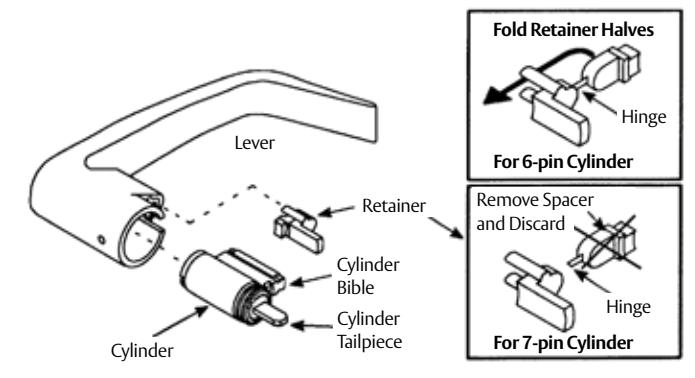
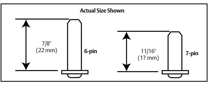
Figure 10 Cylinder Installation
d
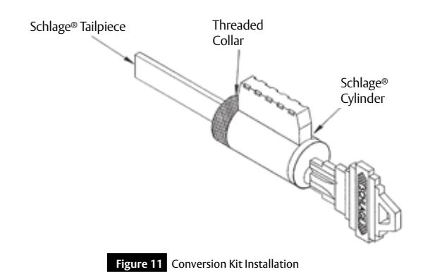
Conversion Kit
To convert Schlage® cylinders with CL3500 lockset (Figure 11):
- Remove threaded collar and Schlage® tailpiece.
- Install CL3500 tailpiece with threaded collar. Adjust collar for proper end play of plug.

5 Lever Removal Installation
| Lever Style | Removal | Install |
|---|---|---|
|
Push / Turn Button
Release Hole Lever Assembly Button |
Hold in button, push release
tool into release hole, remove lever. |
Push button in.
Slide lever on. Make sure lever will not pull off. |
|
Plain Lever
Release Hole Lever Assembly |
Push release tool into release
hole, remove lever. |
Slide lever over lever catch.
Make sure lever will not pull off. |
|
Cylinder Lever
Release Hole Lever Assembly Key |
Rotate key 45° clockwise
(from shed position). Push release tool into release hole, remove lever. Lever Key Cylinder |
Insert key and rotate 45°
(from shed position). Slide lever on. Make sure lever will not pull off. |
|
Interchangeable Core Lever
Lever Catch (Move in direction of arrow) Rose Lever |
Remove core and tailpiece
(page 6). Use flat blade screwdriver to pull back lever catch, remove lever. |
Slide lever over lever catch.
Make sure lever will not pull off. |
Corbin Russwin, Inc. 225 Episcopal Road Berlin, CT 06037 USA Phone: 800-543-3558 Fax: 800-447-6714 www.corbinrusswin.com
ASSA ABLOY is the global leader in door opening solutions, dedicated to satisfying end-users needs for security, safety, and convenience