


Installation Instructions

CK4800 Series Cylindrical Lock
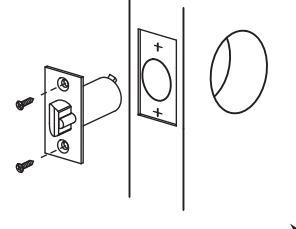
1 Verify door prep using the provided door marker
2 Install Latch
• Mount latch in door.
3 Remove Inside Knob
• If received with knob engaged, depress knob catch with the release tool and pull knob off spindle.

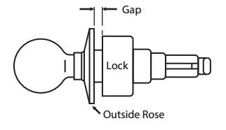
4 Adjust for Door Thickness
• Rotate outside rose in or out, depending on door thickness. Lock will fit any door from 1-3/8" to 1-3/4".
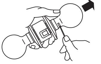
Release Tool
1/8´´ GAP FOR 1 - 3/8´´DOORS 1/4´´ GAP FOR 1 - 3/4´´DOORS
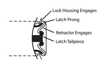
5 Install Outside Assembly
• Lock housing must engage latch prongs and retractor must engage latch tailpiece.
Note: If guard bolt function is installed, do not attempt to mount lock when door is closed. Guard bolt tailpiece will interfere.
Note: Depress latch bolt slightly to allow retractor to engage latch tailpiece.
On cylinder functions make sure keyway is at 6 o'clock position. See page 2 to reverse cylinder.

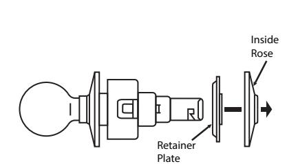
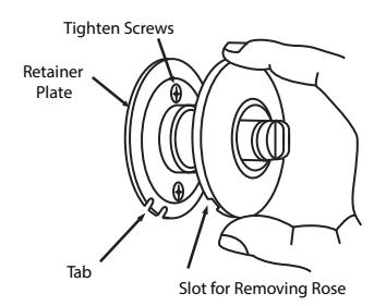
6 Install Retainer Plate and Rose
- Slip on retainer plate and fasten with two machine screws.
- Position spring clip notch and snap rose over retainer plate.

This product can expose you to lead which is known to the state of California to cause cancer and birth defects or other reproductive harm. For more information go to www.P65warnings.ca.gov.
Attention Installer:
Please read these intructions carefully to prevent missing important steps.
Note: Improper installation may result in damage to lock and void factory warranty.
1-800-543-3658 • techsupport.corbinrusswin@assaabloy.com

Install Inside Knob
Line up slot in shank with knob catch in spindle. Slide knob on to spindle. Depress knob catch and push knob into engaged position.
Note: Lockset should be in the unlocked position when replacing the inside knob or handle.

Cylinder Orientation
When a cylinder function lock is correctly installed, the key should be inserted into the lock in this orientation.
If not, reverse cylinder as follows:
- 1. Insert key fully into cylinder.
- 2. Press knob catch with the release tool.
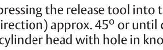
- 3. Turn key (in clockwise direction) aprox. 45° or until depression of the knob catch is felt with the release tool; pull off knob.
- 4. Rotate knob 180° (so that keyway is at 6 o'clock position as shown above). Push knob on to shank until it contacts knob catch.
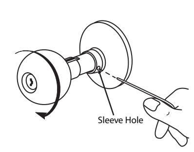
- 5. Release knob catch by pressing the release tool into the outside knob sleeve hole; turn key (in clockwise direction) approx. 45° or until depression of the knob catch is felt.
- 6. Checking alignment of cylinder head with hole in knob, push knob until knob catch "clicks" into position.
Knob Catch

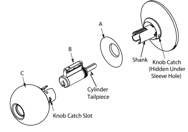
Reassembly
When the cylinder has been removed completely as for purposes of rekeying, reassemble as follows:
- Slip knob collar over shank (A).
- Insert cylinder fully, engaging tail piece (B).
- Slip knob on until it bottoms against knob catch (C).
- Insert key fully into cylinder, press knob catch into the outside knob sleeve hole.
- Turn key (in clockwise direction) approx. 45° or until depression of the knob catch is felt with the release tool.
- Checking alignment of cylinder head with hole in knob, push knob until knob catch "clicks" into position.
- Pull collar back into proper position against knob.
Note: For CK4855 function, check to determine that the slotted member which engages the cylinder tail piece has been rotated clockwise fully and lies in a vertical position.
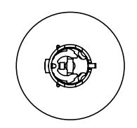
*Slotted Member Front View
1-800-543-3658 • techsupport.corbinrusswin@assaablov.com
Copyright © 2022 ASSA ABLOY Access and Egress Hardware Group, Inc. All rights reserved. Reproduction in whole or in part without written permission of ASSA ABLOY Access and Egress Hardware Group, Inc. is prohibited. Patent pending and/or patent www.assaabloydss.com/patents.
Experience a safer and more open world
FM640 - 05/22