← Corbin
Installation Instructions
CK4300 Series Grade 1 Cylindrical Knob Lockset
In U.S.: In Canada: Corbin Russwin, Inc. ASSA ABLOY Door Security Solutions Canada 225 Episcopal Road 160 Four Valley Drive Berlin, CT 06037 USA
Vaughan, Ontario, Canada L4K4T9 www.assaabloy.ca
Technical Product Support: Phone: 888-607-5703
www.corbinrusswin.com
FM407 (08/15)
CK4300 Series Grade 1 Cylindrical Knob Lockset

ASSA ABLOY
Door Preparation
Position Template
-
1. Fold and apply template on the high edge of beveled door at the desired height from floor.
- 40-5/16" (1,024mm) is the recommended height from floor
- 2. Mark Centerline on both faces and edge of door.
- 3. Mark the drill points for lock and latch.
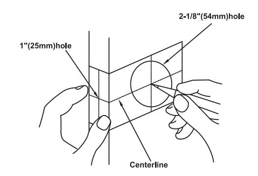
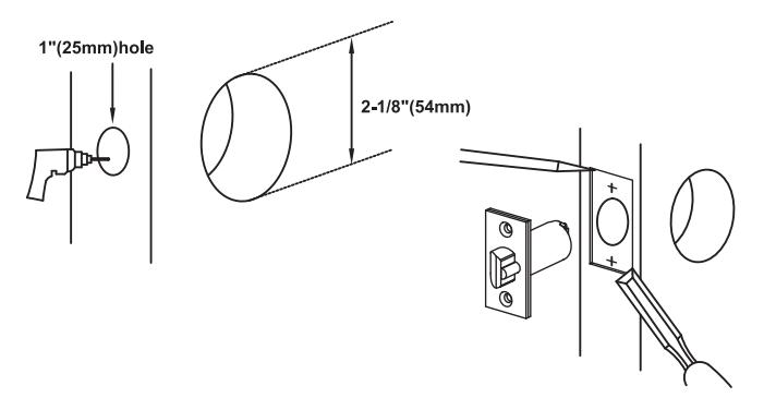
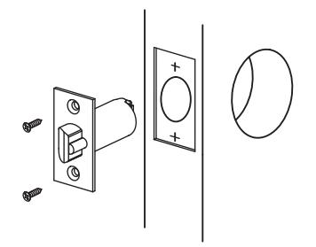
Drill Trim Holes
- 1. Drill 1"(25mm) diameter hole from the edge of door that intersects 2-1/8"(54mm) hole.
- 2. Drill 2-1/8" diameter hole from both sides of door to the center of door.
- Mortise 5/32"(4mm) deep cutout using latch plate on the door edge for latch face.
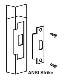
Install Strike
- 1. Mortise door jamb to fit strike.
- 2. Make sure to align strike and latchbolt centers.
- 3. Secure strike with screws provided.
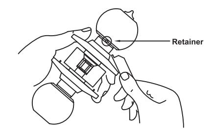
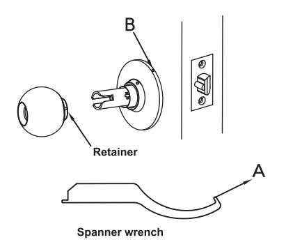
Prepare Inside Trim for Installation
- Depress retainer with the end of spanner wrench through small hole in knob cap.
- 2. Pull inside knob off and remove inside rose.
CK4300 Series Grade 1 Cylindrical Knob Lockset

ASSA ABLOY
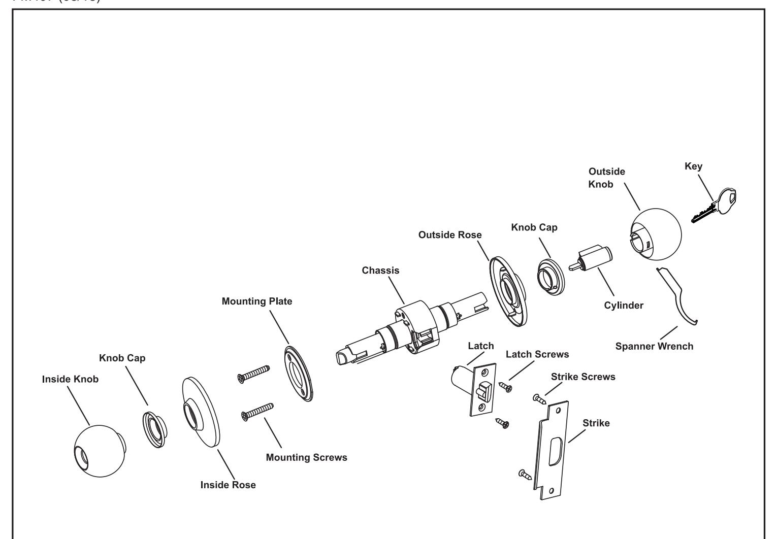
Lock Preparation
Outside Knob Removal and Cylinder Installation
- 1.To remove the outside knob for cylinder installation, depress retainer with the end of the spanner wrench through the small hole in the knob cap.
- 2. Pull outside knob off the lock chassis.
- 3. Install the cylinder into the outside knob.
- 4. Align the tab on the inside diameter of the knob cap with the slot in the knob spindle and press into position.
- 5. Prior to assembling the outside knob to the lock, adjust for door thickness if other than 1-3/4". See below.
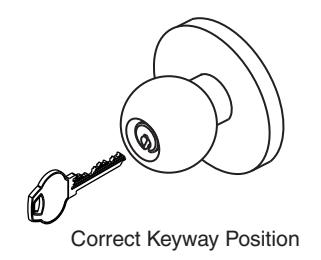
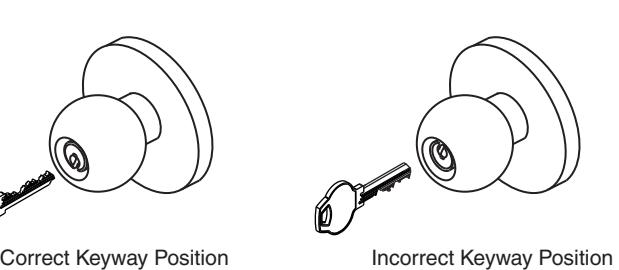
- 6. Align the outside knob with the chassis verifying the correct keyway position.
- 7. Slide the outside knob assembly over the chassis spindle until the knob stops.
- 8. Insert the key into the cylinder and rotate 90 degrees and push the knob into position.
"A"
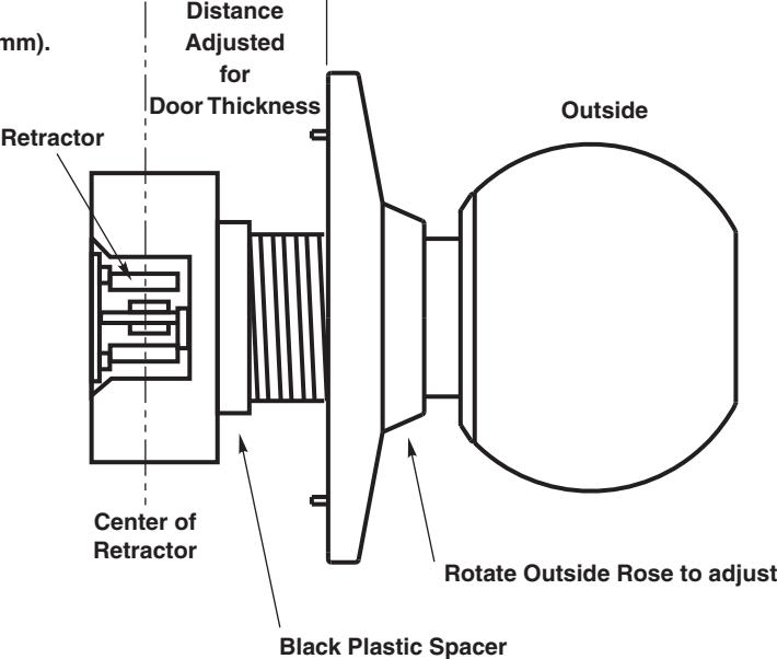
Adjust for Door Thickness (If necessary)
Lock is packed preadjusted for 1-3/4" (44mm) doors.
- 1. Rotate the outside rose nut assembly until proper dimension is reached for required door thickness. See chart.
- 2. Measure from the underside of the rose to the center of the retractor.
- 3. Remove the black plastic spacer to adjust below 1-3/4" (44mm).
| Door Thickness | Dimension "A" |
|---|---|
| 1-3/8" (35mm) | 11/16" (17mm) |
| 1-1/2" (38mm) | 3/4" (19mm) |
| 1-3/4" (44mm) | 7/8" (22mm) |
| 2" (51mm) | 1" (25mm) |
CK4300 Series Grade 1 Cylindrical Knob Lockset

ASSA ABLOY
Installation Instructions
NOTE: DO NOT INSTALL LOCK WITH DOOR CLOSED.
Install Latch
- 1. Beveled side of bolt should face the door jamb.
- 2. Install two(2) latch screws and check the door swing.
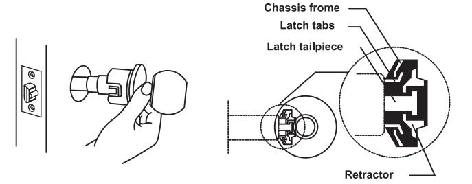
Install Outside Trim
- 1. With latch in place, install chassis from outside of the door.
- 2. Make sure that latch tabs fit into chassis frame and latch tailpiece fits into the retractor as shown.
Install Inside Trim
- 1. Place mounting plate in position and tighten two(2) Mounting screws.
- 2. Rotate inside rose clockwise to lock and tighten securely with spanner wrench supplied.
NOTE
- Catch small lug "A" of spanner wrench in small hole "B".
- Turn clockwise until tight.
- 3. Slide inside knob onto spindle.
With retainer hole in knob facing edge of door push until retainer snaps into place.
Test the Operation of the Lockset
Cycle the lock in both the locked and unlocked positions.
-
1. If Lock functions smoothly when door is open, but binds when closed:
- a. Check door.
- b. Check hinges. They should not be loose or have excessive wear on knuckles.
-
2. Latchbolt will not deadlock.
- a. Check if strike is out of line with latchbolt or gap between door and jamb is too great.
- b. Realign strike or shim strike out towards flat area of latchbolt.
-
If latchbolt doesn't retract or extend properly, latcbolt tail and retractor may not be properly positioned.
- a. Remove lockset. Look through 2-1/8" hole and verify latchbolt tail is centered between top and bottom of hole.
- Remove latchbolt and insert lockset. Look through latch hole and verify retractor mouth is centered in hole. Adjust outside rose if not.
- c. Rebore holes if necessary to line up retractor and tail.