


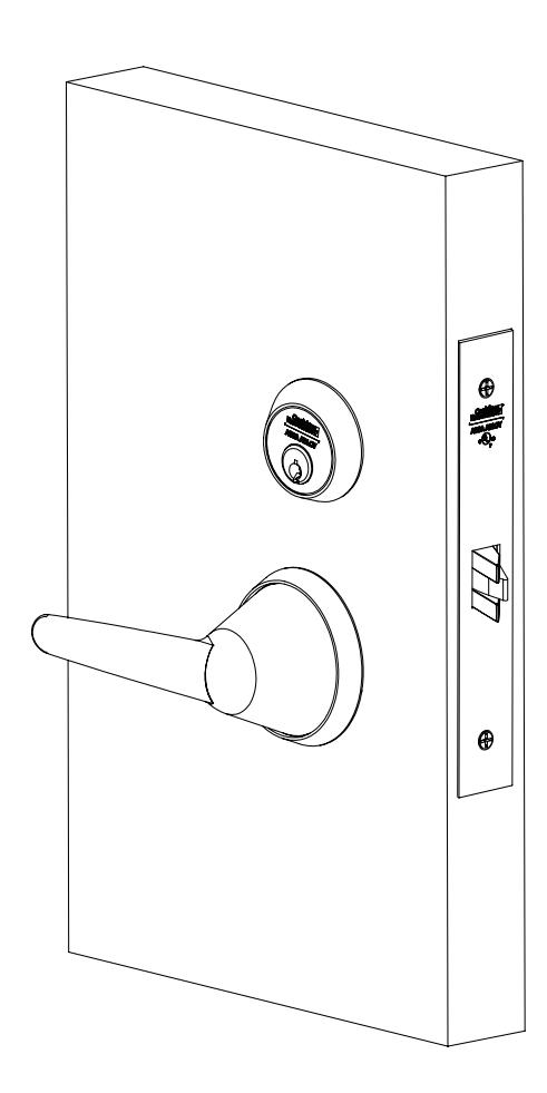
BLSS Trim
For Mortise Locks
ML2000 Series

This product can expose you to lead which is known to the state of California to cause cancer and birth defects or other reproductive harm. For more information go to www.P65warnings.ca.gov.
BLSS Trim
ML2000 Series
Installation Instructions

| TOC | Table of Contents | |
|---|---|---|
| 1 | Tools Required 2 | |
| 2 | Package Contents 3 | |
| 3 | Mortise Lock Handing Instructions 3 | |
| 4 | Door Preparation 4 | |
| 5 | BLSS Trim Installation 6 | |
| 6 | Installation 7 | |
| a | Install Adapter Clutch 7 | |
| b | Install Outside Lever Assembly 7 |
c Install Outside Trim . . . . . . . . . . . . . . . . . . . . . . . . . . . . . . . . . . . . . . . . . . . . . . . . . . . . . . . . . . . . . 8
d Install Inside Adapter Plate Assembly . . . . . . . . . . . . . . . . . . . . . . . . . . . . . . . . . . . . . . . . . . . 8
e Install Lock Front . . . . . . . . . . . . . . . . . . . . . . . . . . . . . . . . . . . . . . . . . . . . . . . . . . . . . . . . . . . . . . . 9
f Install Turn-Piece . . . . . . . . . . . . . . . . . . . . . . . . . . . . . . . . . . . . . . . . . . . . . . . . . . . . . . . . . . . . . . . 9
g Install Coin-Turn . . . . . . . . . . . . . . . . . . . . . . . . . . . . . . . . . . . . . . . . . . . . . . . . . . . . . . . . . . . . . . . 10
Attention Installer
Please read these instructions carefully to prevent missing important steps.
Notes:
- Improper installation may result in damage to lock and void factory warranty.
- Other product brand names may be trademarks or registered trademarks of their respective owners and are mentioned for reference only.
1 Tools Required
- Phillips Screwdriver (# 2)
- Torx Tamper Resistant Driver (T-20)
- Torx Tamper Resistant Driver (T-10)
- Hex Key Driver 5/64"

2 Package Contents Adapter Plate Pack 858F628 Outside Lever Assembly 858F617-32D Rose Assembly 858F087-32D Inside Lever Assembly 858F607-32D
Figure 1
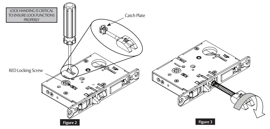
3 Mortise Lock Handing Instructions
- 1. Move red locking screw to side of lock body being locked.
- 2. Push in latch. Depress catch plate with screwdriver. (Figure 2)
- 3. Pull latch out of lock body and turn latch over. (Figure 3)

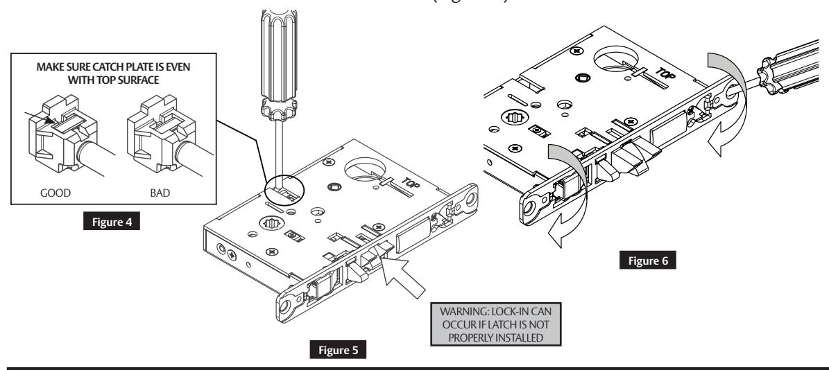
3 Mortise Lock Handing Instructions (cont.)
4. Push in latch while holding screwdriver behind latch tail. (Figure 5)
Note:
Ensure that latch is pushed in until catch plate is no longer depressed. (Figure 4)
5. Rotate lock front to match bevel of door as shown. (Figure 6)
4 Door Preparation
Important:
Be sure to hand the lockbody before installing.
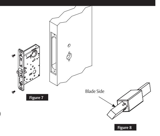
- 1. Insert mortise lock into door and fully tighten 1" lock mounting combination screws. (Figure 7)
- 2. Turn-piece functions only: Insert turn-piece door marker spindle into lockbody on inside of door.
Note:
Use square side of door marker spindle. (Figure 8)
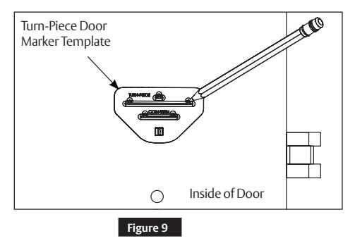
- 3. Turn-piece functions only: Slide turn-piece door marker over spindle.
- 4. Turn-piece functions only: Mark three holes for turn-piece. (Figure 9)
- 5. Coin-turn functions only: Insert turn-piece marker spindle into lockbody on outside of door.
Note:
Use square side of door marker spindle. (Figure 8)
FM351 08/19

4 Door Preparation (cont.)
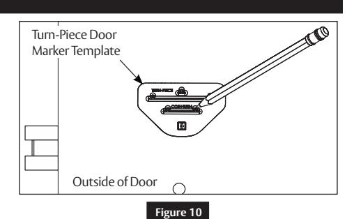
- 6. Coin-turn functions only: Slide turn-piece door marker template over spindle.
- 7. Coin-turn functions only: Mark two holes for coin-turn. (Figure 10)
- 8. Remove lockbody from door.
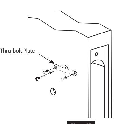
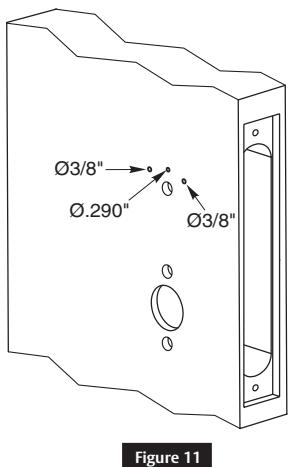
- 9. Turn-piece functions only: Drill one middle hole (.290") and two outer holes (3/8") halfway through door. (Figure 11)
- 10. Coin-turn functions only: Drill two holes (1/8") halfway through door. (Figure 12)
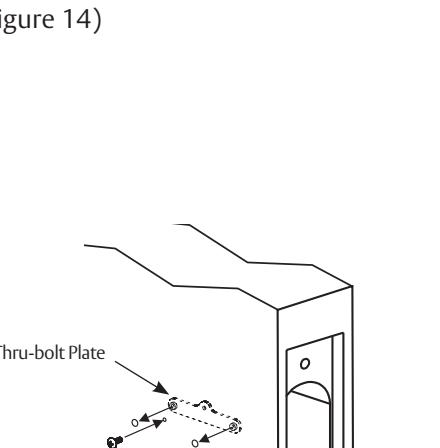
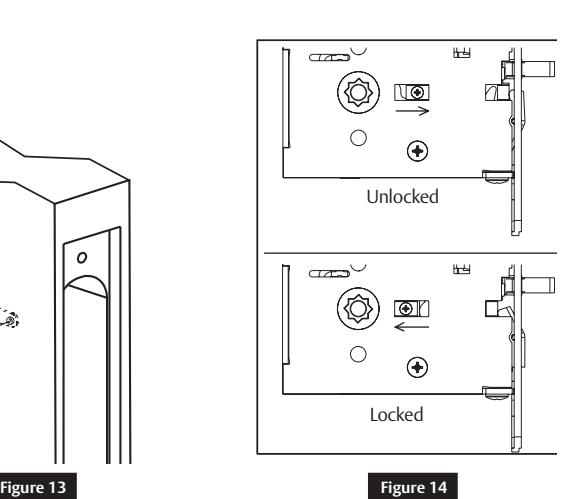
- 11. Turn-piece functions only: Install turn-piece thru-bolt plate using truss head screw. Leave screw slightly loose. (Figure 13)
Note:
The thru-bolt plate is installed inside the door pocket.
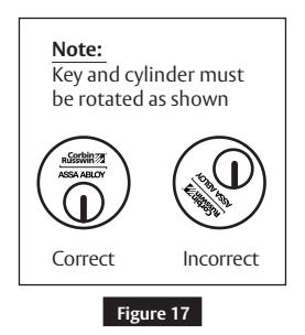
12. Insert mortise lockbody into door and loosely tighten 1" lock mounting combination screws.
Note:
Ø1/8"
Figure 12
Make sure lock is unlocked. (Figure 14)
FM351 08/19
Copyright © 2019, ASSA ABLOY Access and Egress Hardware Group, Inc. All rights reserved. Reproduction in whole or in part without the express written permission of ASSA ABLOY Access and Egress Hardware Group, Inc. is prohibited.

5 BLSS Trim Installation
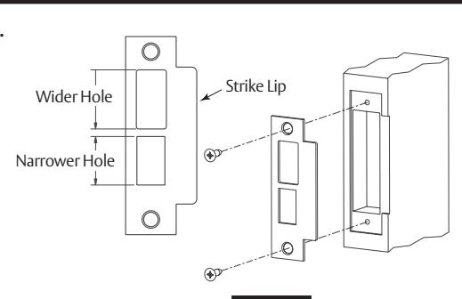
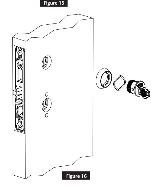
1. Install strike using 3/4" strike mounting screws.
Note:
Strike must be oriented with narrower hole on lower half of strike and strike lip towards pull side of door. (Figure 15)
2. Cylinder functions only:
Slide cylinder(s) through spring and collar, threading into lockbody until cylinder face is flush with collar. (Figure 16)
Note:
Pull key slightly out of cylinder to help thread into lockbody.
Note:
Cylinder must be oriented correctly. (Figure 17)

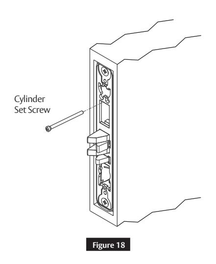
Tighten cylinder set screw. (Figure 18)
4. Fully tighten lock mounting screws.
For installation assistance contact Corbin Russwin

6 Installation
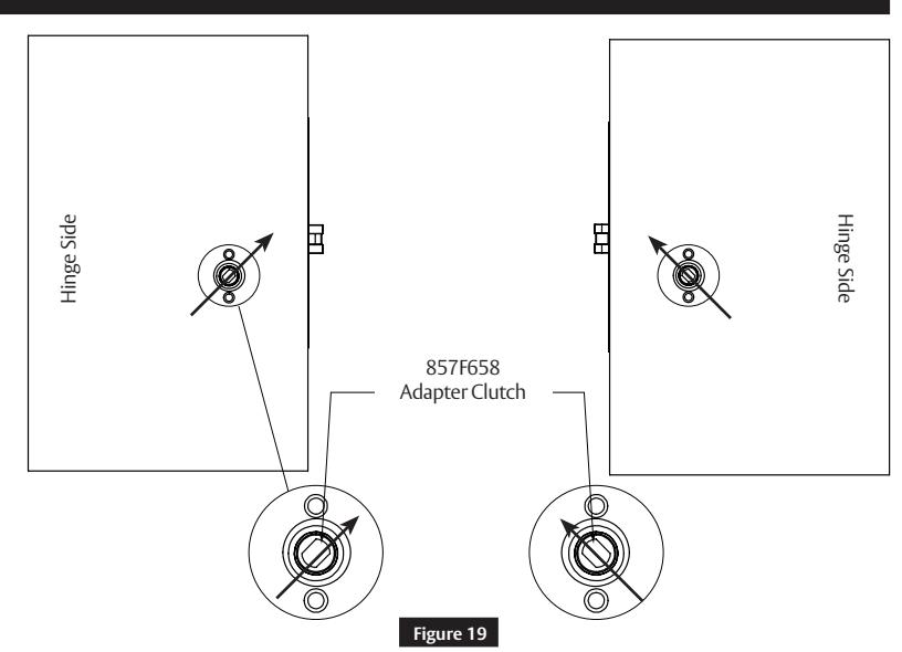
a Install Adapter Clutch
1. Install adapter clutch into mortise lock hub. (Figure 19)
Note:
Adapter clutch is oriented toward latchbolt as shown.
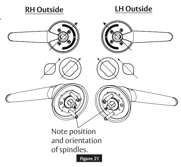
b Install Outside Lever Assembly
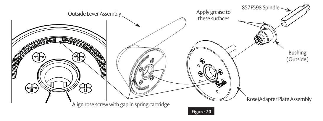
- 1. Use outside bushing and spindle to connect rose/adapter plate assembly to outside lever assembly. (Figure 20)
- 2. Insert spindle into bushing; ensure that spindle is inserted no more than ¾" deep.
- 3. Use spindle to rotate bushing clockwise into outside lever hole.
- 4. Fully tighten bushing, then unthread bushing just enough to allow spindle to be inserted into lever, keeping bushing as tight as possible.
- 5. Once assembled, spindle orientation should be as shown. (Figure 21)
Note:
Longer spindle used on outside
FM351 08/19

6 Installation (cont.)
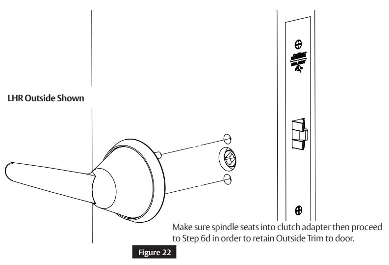
c Install Outside Trim
d Install Inside Adapter Plate Assembly
1. Install inside adapter plate assembly using two (2) machine screws. (Figure 23)
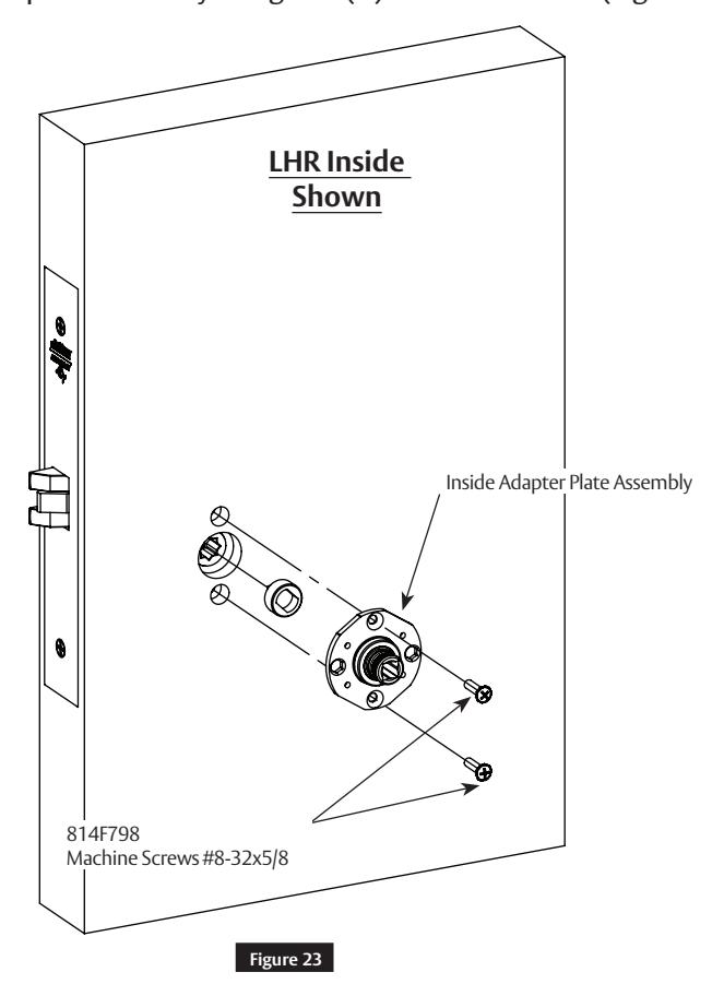
8

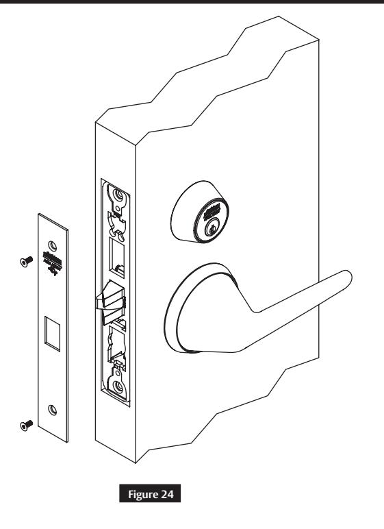
6 Installation (cont.)
e Install Lock Front
1. Install lock front using two (2) front screws. (Figure 24)
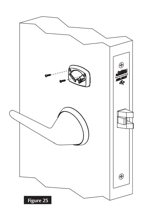
f Install Turn-Piece
1. Install turn-piece loosely using two turn-piece mounting screws. (Figure 25)
Note:
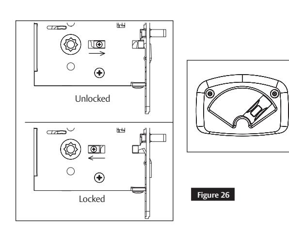
Make sure lock is unlocked and turn-piece is rotated towards latch.
2. Adjust location of turn-piece on door until turn-piece rotates easily, then fully tighten mounting screws. (Figure 26)
BLSS Trim
ML2000 Series
Installation Instructions

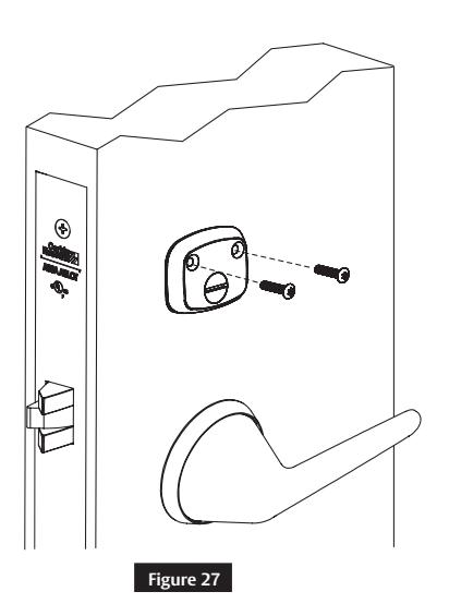
g Install Coin-Turn
1. Install coin-turn using two surface mount screws. (Figure 27)


Page intentionally left blank.

Corbin Russwin, Inc. 225 Episcopal Road Berlin, CT 06037 USA Phone: 800-543-3558 Fax: 800-447-6714 www.corbinrusswin.com