


Installation & Wiring Instructions

EcoFlex® Electrified (NAC-) Multi-Point Series Lock with High-Security Monitoring Options
FE6600/BL6600/MP6600 Series
Note
- Disconnect all input power before beginning installation to prevent electrical shock.
- Installer must be a trained, experienced service person.
- All wiring must comply with applicable local electrical codes, ordinances, and regulations.

This product can expose you to lead which is known to the state of California to cause cancer and birth defects or other reproductive harm. For more information go to www.P65warnings.ca.gov.
FM459 8/20
(NAC-) with High-Security Monitoring Options
EcoFlex® Electrifi ed FE6600/BL6600/MP6600 Series Multi-point Lock
Installation & Wiring Instructions

1 Overview
a Description
The NAC- mortise lock provides increased security over typical electrified mortise locks with dead bolt, dead bolt monitoring, request to exit monitoring, and door status monitoring built into a single lock. This lock can also be specified with factory installed and tested end-of-line resistors monitoring the request to exit and door position outputs.
The high security monitoring options of our industry-leading Integrated Wiegand locks are now available in a mortise lock that can be used as a stand-alone electrified lock or in conjunction with a wall reader. Every NAC lock is shipped with door position and request to exit monitoring installed. NAC locks ordered with deadbolt are supplied with deadbolt monitoring.
If your lock is confi gured with End of Line Resistors, reference instruction sheet FM472 for the wiring of RX & DPS outputs.

CAUTION: The voltage applied to the lock actuator must not exceed 10% of rated voltage.
If the voltage exceeds this value, the actuator may be damaged.
b Specifi cations/Functions
EcoFlex Actuator
- Type 12/24VDC, Continuous Duty
- Actuator Draw = 15mA
- Maximum two (2) locks per 1Amp power supply (500mA peak current draw)
- Fail Safe Models: NAC- 12VDC and NAC- 24VDC
- Fail Secure Models: NAC- 12VDC and NAC- 24VDC
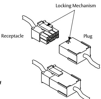
c ElectroLynx® Connector System Notes
The system is designed to be installation-friendly with connectors from the Locking Mechanism electric hinge through the door to the lock. External electrical connections are made to a harness that extends from the frame.
IMPORTANT:
The plug and receptacle connectors are designed to mate and lock together as shown in the illustration. Plug the connectors into each other with the locking mechanism aligned as indicated.
Do NOT force connectors on any other way.
ElectroLynx®
As part of their promise to provide innovative, fast and effective, and higher security solutions to their customers, ASSA ABLOY Group companies offer ElectroLynx, a universal quick-connect system that simplifi es the electrifi cation of the door opening. ElectroLynx®is a registered trademark of ASSA ABLOY, Inc.
2 Installation and Wiring
a Installation Notes
Install mortise lock and electric hinge. With new applications, an ElectroLynx® raceway harness with 8 & 4-pin connectors will be pre-installed inside the door by ASSA ABLOY door manufacturer when specified during ordering process. Raceway harness kits are also available for retrofit applications.
If door does not have an ElectroLynx raceway harness with connectors, either consult factory for raceway retrofit kit or cut the connectors off product and hard-wire per facility wiring requirement.
(NAC-) with High-Security Monitoring Options
EcoFlex® Electrifi ed FE6600/BL6600/MP6600 Series Multi-point Lock


2 Installation and Wiring, continued
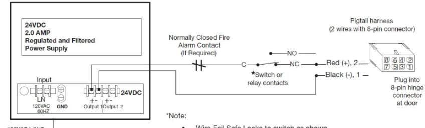
b Installation and Wiring Instructions
Sample wiring for NAC-24V lock with a 24VDC regulated and filtered power supply.
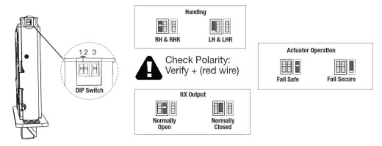
c Confi gure DIP Switch Settings
IMPORTANT:
This product is built and factory tested to the configuration specified. Any change to the 3-position DIP-switch settings located at the bottom of the mortise lock body must be made prior to lock installation.
d NAC EcoFlex Mortise Lock Wiring Diagrams
Check polarity: Verify + (red) wire
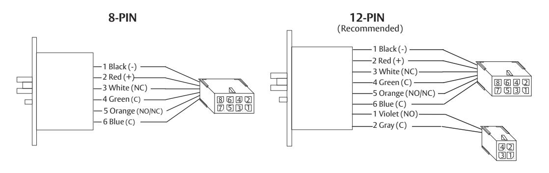
| Connector | 8-PIN MOLEX | 4-PIN MOLEX | |||||
|---|---|---|---|---|---|---|---|
| Circuit |
1
2 |
3
4 |
5
6 |
7 | 8 |
1
2 |
3
4 |
| Connection | 12/24VDC Lock Input | Door Position | Request to Exit | Empty | Empty | Deadbolt Monitoring | Empty |
| Wire Color |
Black
Red |
White Green |
Orange
Blue |
Violet
Gray |
|||
| Description | NEG POS | NC COM | NO/NC COM |
NO
COM |
|||

Corbin Russwin 225 Episcopal Road Berlin, CT 06037 USA Phone: 800-543-3558