Installation Instructions Installation Instructions
CLX3300 Series with BHSS Trim

1 Tools Required
-
5/32" drill bit 1/2
"
drill bit 7/16" drill bit 1/8" drill bit
- #2 Phillips screwdriver T25 Security Torx® screwdriver T15 Security Torx® screwdriver
2 Product Components
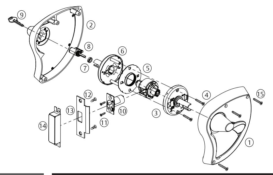
| Fig. | Description |
|---|---|
| 1 | Inside escutcheon & lever assembly |
| 2 |
Outside escutcheon & lever
assembly |
| 3 | Inside spring housing assembly |
| 4 |
Screws - through-bolt (2) #12-24
x 1-1/2" |
| 5 | Lockbody assembly with rose liner |
| 6 | Outside spring housing assembly |
| 7 | Cylinder spacer |
| 8 | Cylinder |
| 9 | Key |
| 10 | Latch |
| 11 | Screws - latch (2) #8-32 x 3/4" |
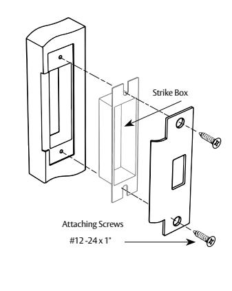
| 12 | Screws - strike (2) #12-24 x 1" |
| 13 | Strike |
| 14 | Strike box (Optional) |
| 15 |
Screws- through-bolt (3) #10-24 x
3-1/2" |
3 Door Preparation
- 1. Use template FM623 to mark the door (Figure 1).
- 2. Drill the door according to the template.
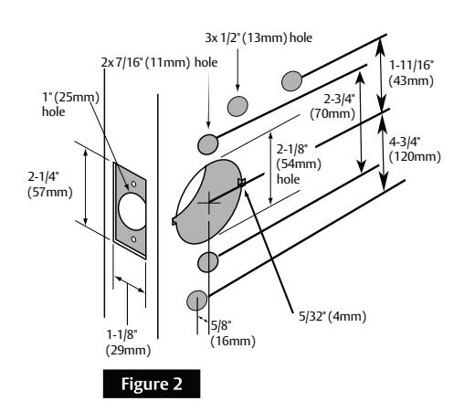
- 3. Verify the dimensions (Figure 2).
- 4. Install the strike (Figure 3)
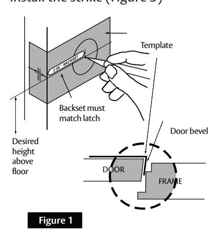
IMPORTANT
- The accuracy of door preparation is critical for proper functioning and security of this lever handle lock. Misalignment can cause premature wear and a lessening of security.
- Be sure to verify backset before marking and drilling door.
For installation assistance contact Corbin Russwin
1-800-543-3658 • techsupport.corbinrusswin@assaabloy.com • www.corbinrusswin.com
CLX3300 Series with BHSS Trim
Installation Instructions

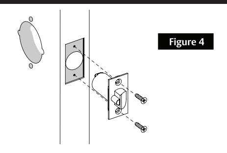
4 Latch Installation
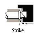
Insert latch in door. (Be sure bevel edge of bolt faces strike plate.) Attach with " screws supplied.
Important: Deadlocking latch must stop on strike when door is closed.
5 Door Thickness Adjustment (if necessary)
Lock is factory preset for 1-3/4" (44mm) doors unless specified. To adjust lock to door thickness if other than 1-3/4" (44mm):
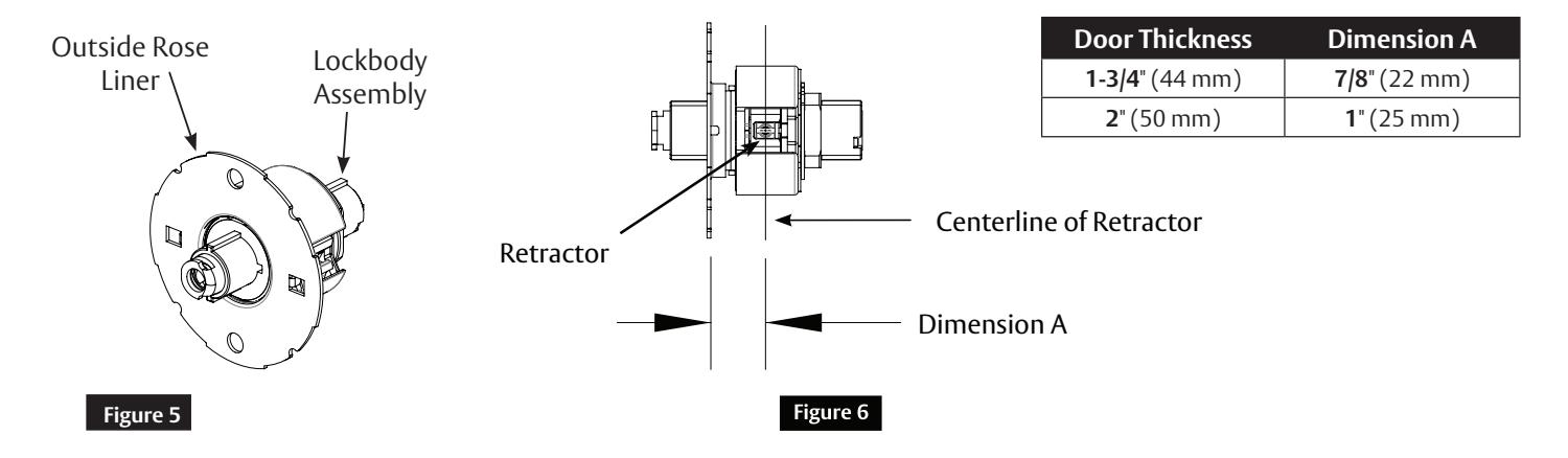
- 1. Remove outside spring housing from lockbody assembly. (Figure 5)
- 2. Rotate outside rose liner to adjust lock to fit door thickness, so distance (Dimension A) from inside surface of liner to centerline of retractor is half the thickness of the door. (See chart and Figure 6)
- 3. Reassemble outside spring housing onto lockbody assembly.
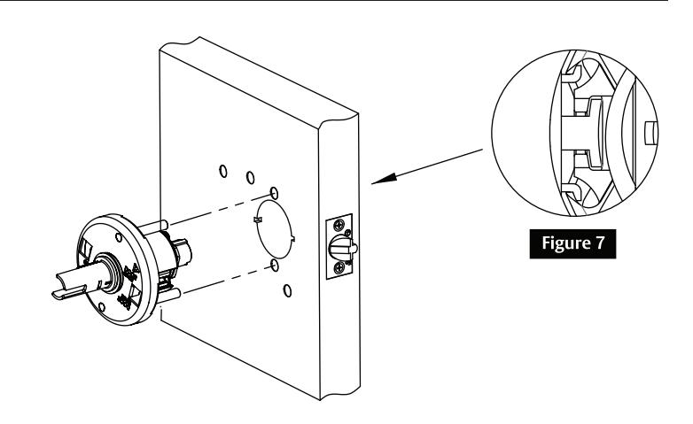
6 Install Outside Lockbody Assembly
To adjust lock to door thickness if other than 1-3/4" (44mm) refer to Section 5.
Insert lockbody assembly into door from outside making sure that lockbody hooks latch case and retractor engages bolt tail(s). (Figure 7)
DO NOT FORCE. (If lockbody does not engage latch easily, check door preparation for errors.)
Latch bolt tail should be centered in depth of retractor. If it is not, refer to Section 5 to properly adjust the lock for door thickness.
FM589 07/22
CLX3300 Series with BHSS Trim
Installation Instructions

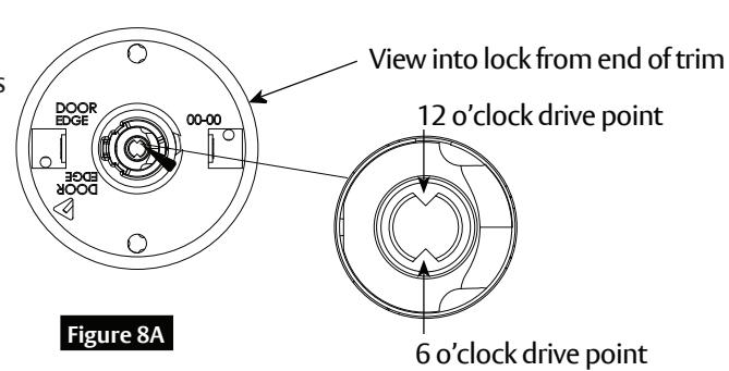
7 Cylinder Installation

a Standard Cylinder (Figure 8)
IMPORTANT
Before installing cylinders:
• Use a flat blade screwdriver to rotate cam until the driver points are in a 6 and 12 o'clock position. (Figure 8A)
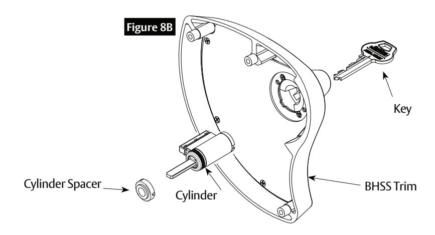
Verify that the cylinder spacer is already installed into the shank on the outside spring housing assembly. Cylinder spacer should be removed for 7-Pin cylinder.
Note orientation of spacer, if it needs to be reinstalled.
1. Install cylinder into the lever. (Figure 8B)
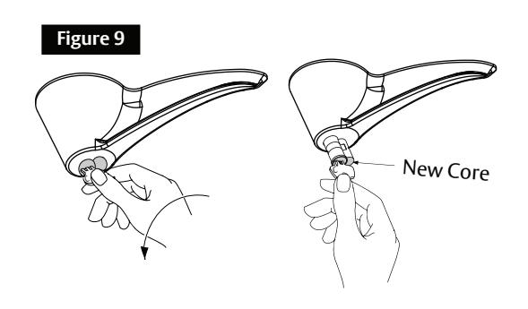
b Interchangeable or Removable Core (Figure 9)
- Remove temporary construction core or plastic core. If keyed, use Control Key. Rotate 15° and pull.
- Insert permanent core into lever with control key. Rotate 15° and remove key.
part without the express written permission of ASSA ABLOY Access and Egress Hardware Group, Inc. is prohibited.
CLX3300 Series with BHSS Trim
Installation Instructions

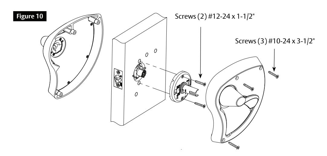
8 Install Inside and Outside Escutcheon & Lever Assemblies
- 1. Align and insert inside spring housing onto the installed lockbody.
- 2. Install (2) #12-24 x 1-1/2 " screws to tighten the spring housing to the door.
- 3. Mount inside escutcheon and lever assembly over the inside spring housing.
- 4. Mount outside escutcheon and lever assembly over the outside spring housing.
- 5. Secure the assemblies using the (3) screws #10-24 x 3-1/2 " (Figure 10)
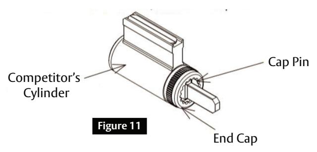
9 Cylinder Options
a Lever to Accept Schlage® or Yale® Fixed Core Cylinder (M06 or YC Option)
- 1. Provided less cylinder.
- 2. Depress cap pin and unscrew end cap to remove tailpiece from competitor's cylinder. (Figure 11)
- 3. Insert new tailpiece in orientation shown.
- 4. Reassemble end cap over new tailpiece.