


Installation Instructions
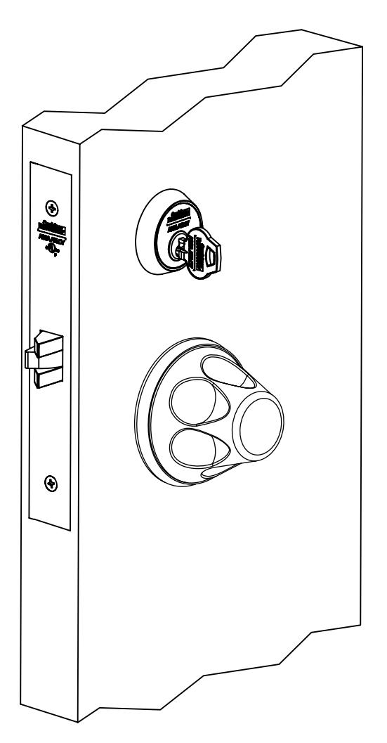
Anti-Harm Knob Trim (HSS) for ML2000 Series Mortise Locks

| TOC | Table of Contents | |
|---|---|---|
| 1 | Mortise Lock Handing Instructions 2 | |
| 2 | Mortise Lock Door Preparation & Installation 3 | |
| 3 |
HSS Trim Installation 5
Knob x Knob Lever x Knob |
6
7 |
| 4 | Turn-Piece Installation 8 | |
| 5 | Coin-Turn Installation 8 |
ML2000 Series Mortise Lock
Installation Instructions

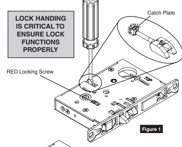
1 Mortise Lock Handing Instructions
- 1. Move the Red locking screw to side of lockbody being locked.
- 2. Push in latch then depress catch plate with screwdriver. (Figure 1)
3. Pull latch out of lock-body and turn latch over. (Figure 2)
4. Push in latch while holding screwdriver behind latch tail. (Figure 3)


NOTE:
PUSH IN LATCH UNTIL CATCH PLATE IS NO LONGER DEPRESSED. (FIGURE 4)
5. Rotate lock front to match bevel of door as shown. (Figure 5)

For installation assistance contact Corbin Russwin 1-888-607-5703 • support@corbinrusswin.com
FM311 11/17
ML2000 Series Mortise Lock
Installation Instructions

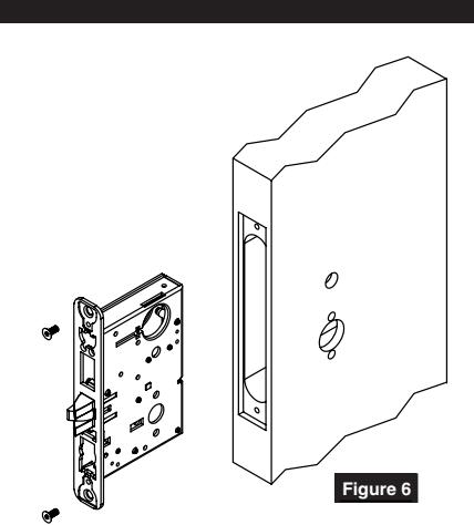
2 Mortise Lock Door Preparation & Installation
Important: Be sure to hand the lockbody before installing. See Section 1.
1. Insert mortise lock into door and fully tighten 1" lock mounting combination screws. (Figure 6)

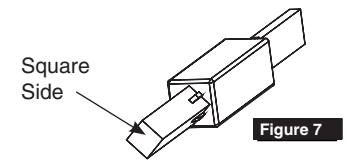
Insert turn-piece door marker spindle into lockbody on inside of door.
NOTE:
USE SQUARE SIDE OF DOOR MARKER SPINDLE. (FIGURE 7)
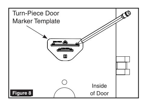
3. TURN-PIECE FUNCTIONS ONLY: Slide turn-piece door marker over spindle.
4. TURN-PIECE FUNCTIONS ONLY: Mark three holes for turn-piece. (Figure 8)

Insert turn-piece marker spindle into lockbody on outside of door.
NOTE:
USE SQUARE SIDE OF DOOR MARKER SPINDLE. (FIGURE 7)
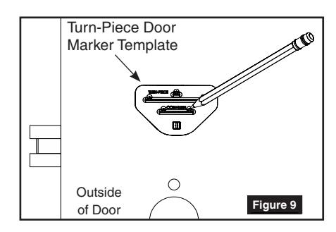
6. COIN-TURN FUNCTIONS ONLY:
Slide turn-piece door marker template over spindle.
7. COIN-TURN FUNCTIONS ONLY:
Mark two holes for coin-turn. (Figure 9)
ML2000 Series Mortise Lock
Installation Instructions

2 Mortise Lock Door Preparation & Installation
8. Remove lockbody from door.
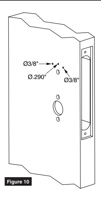
9. TURN-PIECE FUNCTIONS ONLY:
Drill one middle hole (.290") and two outer holes (3/8") halfway through door. (Figure 10)
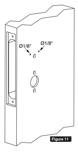
10. COIN-TURN FUNCTIONS ONLY:
Drill two holes (1/8") halfway through door. (Figure 11)
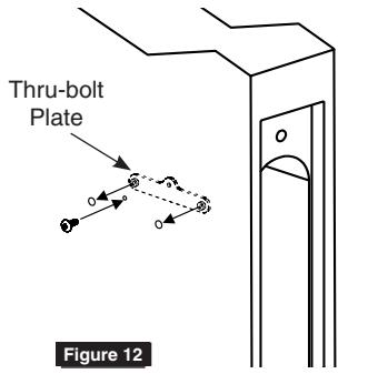
11. TURN-PIECE FUNCTIONS ONLY:
Install turn-piece thru-bolt plate using truss head screw. (Leave screw slightly loose.) (Figure 12)
NOTE:
THE THRU-BOLT PLATE IS INSTALLED INSIDE THE DOOR POCKET.
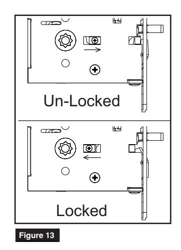
12. Insert mortise lockbody into door and loosely tighten 1" lock mounting combination screws.
NOTE:
MAKE SURE LOCK IS UNLOCKED. (FIGURE 13) MAKE SURE LOCK
ML2000 Series Mortise Lock
Installation Instructions

3 HSS Trim Installation
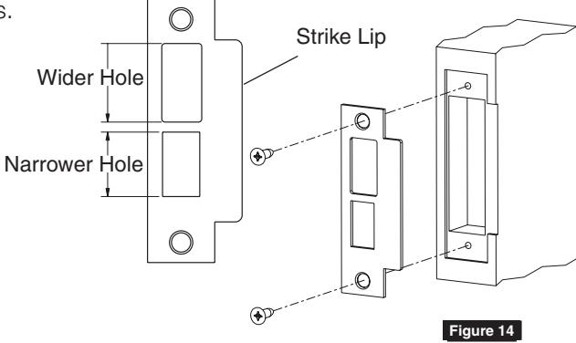
1. Install strike using 3/4" strike mounting screws.
NOTE:
STRIKE MUST BE ORIENTED WITH NARROWER HOLE ON LOWER HALF OF STRIKE AND STRIKE LIP TOWARDS PULL SIDE OF DOOR. (FIGURE 14)
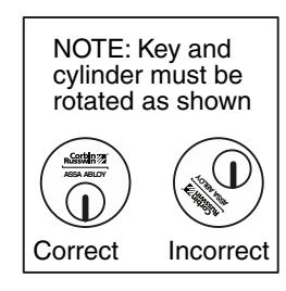
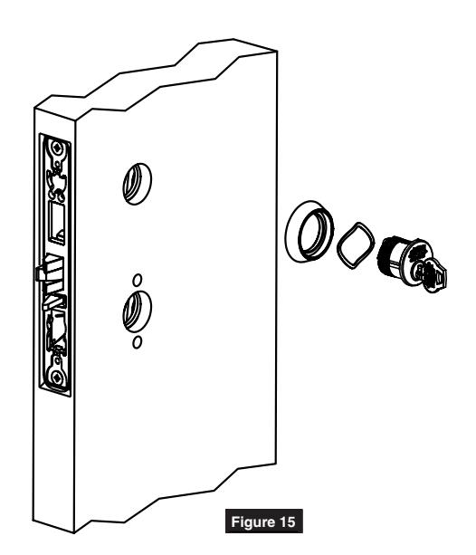
2. CYLINDER FUNCTIONS ONLY:
Slide cylinder(s) through spring and collar, threading into lockbody until cylinder face is flush with collar. (Figure 15)
NOTE:
PULL KEY SLIGHTLY OUT OF CYLINDER TO HELP THREAD INTO LOCKBODY.
NOTE:
CYLINDER MUST BE ORIENTED CORRECTLY. (FIGURE 16)

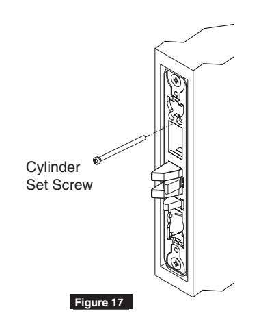
3. CYLINDER FUNCTIONS ONLY:
Install cylinder set screw(s). (Figure 17)
4. Fully tighten lock mounting screws.
ML2000 Series Mortise Lock
Installation Instructions

3 HSS Trim Installation
1 Knob x Knob
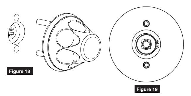
1. Insert outside knob assembly through door and lockbody. (Figure 18)
NOTE:
ALIGN SPINDLE WITH SQUARE HOLE IN LOCKBODY AS SHOWN IN (FIGURE 19)
2. Install inside knob assembly by threading mounting screws into lugs from outside knob assembly with supplied Allen wrench. (Figure 20)
NOTE:
MAKE SURE HOLES IN KNOB ARE ALIGNED WITH SCREWS IN ADAPTER PLATE. ALIGN SPINDLE WITH SQUARE HOLE IN LOCKBODY AS SHOWN (FIGURE 19)
Figure 20
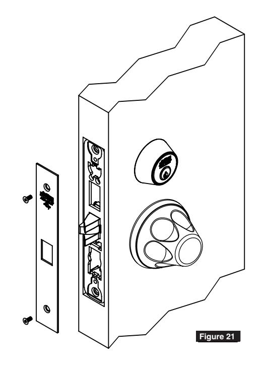
3. Install lock front using two front screws. (Figure 21)
ML2000 Series Mortise Lock
Installation Instructions

3 HSS Trim Installation
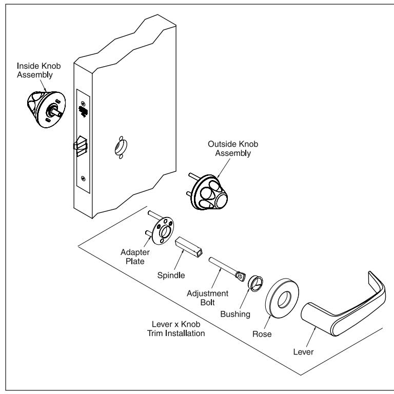
2 Lever x Knob
- 1. Insert outside adapter plate through lockbody and door. (Figure 22)
- 2. Install inside knob assembly by threading mounting screws into lugs from outside adapter plate with supplied Allen wrench. (Figure 23)

ALIGN SPINDLE WITH SQUARE HOLE IN LOCKBODY AS SHOWN. (FIGURE 24)
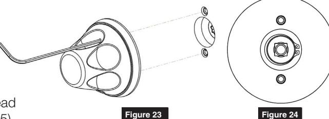
Figure 22
3. Insert outside spindle into lockbody and thread adjustment bolt into inside spindle. (Figure 25)
NOTE:
ALIGN SPINDLE WITH DIAMOND HOLE IN LOCK-BODY AS SHOWN IN (FIGURE 26)
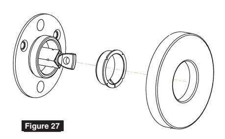
- 4. Install bushing into outside adapter plate then thread rose onto adapter plate. (Figure 27)
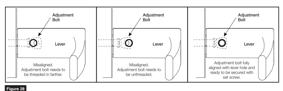
- 5. Install lever by aligning hole in adjustment bolt with threaded hole in lever. Then secure with set screw.
NOTE:
MAKE SURE KNOB IS FULLY INSERTED INTO INSIDE ADAPTER PLATE BEFORE ADJUSTING ADJUSTMENT BOLT. (FIGURE 28)
6. Install lock front using two front screws. (Figure 21 on page 6)

For installation assistance contact Corbin Russwin 1-888-607-5703 • support@corbinrusswin.com

Turn-Piece Installation
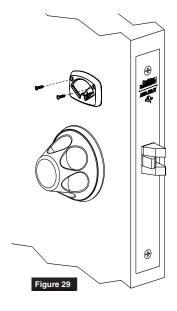
1. Install turn-piece loosely using two turnpiece mounting screws. (Figure 29)
NOTE:
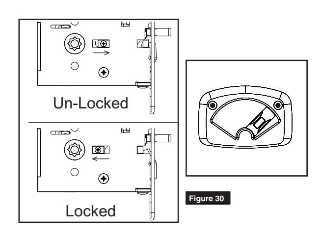
MAKE SURE LOCK IS UNLOCKED AND TURN-PIECE IS ROTATED TOWARDS LATCH. (FIGURE 30)
2. Adjust location of turn-piece on door until turn-piece rotates easily, then fully tighten mounting screws.
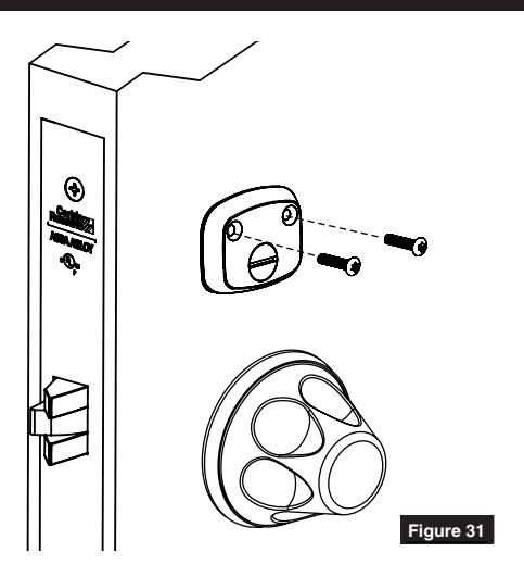
Coin-Turn Installation
1. Install coin-turn using two surface mount screws. (Figure 31)
Corbin Russwin 225 Episcopal Road Berlin, CT 06037 Phone: 800-543-3658 Fax: 800-447-6714 corbinrusswin.com
ASSA ABLOY is the global leader in door opening solutions, dedicated to satisfying end-user needs for security, safety and convenience
Copyright © 2017 Corbin Russwin, Inc., an ASSA ABLOY Group company. All rights reserved. Reproduction in whole or in part without the express written permission of Corbin Russwin, Inc. is prohibited.
For installation assistance contact Corbin Russwin 1-888-607-5703 • support@corbinrusswin.com