


HEAVY DUTY ELECTRICALLY CONTROLLED TRIM

Rim
For use with ED5000 Series Exit Device (Wood and Metal Doors)
Combine simplicity, security and access control in a robust and elegant design with the redesigned Corbin Russwin *9903 and *9905 series electrically controlled exit trim. Utilizing the patented free wheeling system, the redesigned Exit trim provides electrified remote locking and unlocking.
Warning: Changes or modifications to this unit not expressly approved by the party responsible for compliance could void the user's authority to operate the equipment.
Attention Installer
Please read these instructions carefully to prevent missing important steps.
Please Note: Improper installations may result in damage to the lock and void the factory warranty.
Important: The accuracy of the door preparation is critical for proper functioning and security of this lock.
Misalignment can cause premature wear and a lessening of security.
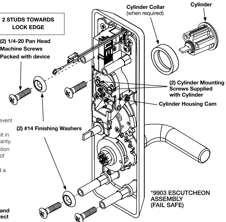
Escutcheon Assembly
Lever is handed, LHR (shown) or RHR.
Note: Lever Return Spring is handed. Hand or trim cannot be changed without correct spring.
LHR, part number 651 F61-8 (Red) RHR, part number 651 F62-8 (Blue)
2 STUDS AWAY FROM LOCK
1. Check cylinder components.
NOTE: Cylinders longer than 1-1/8" (29mm) will require collars.
Refer to Corbin Russwin Cylinder Collar Chart on this page.
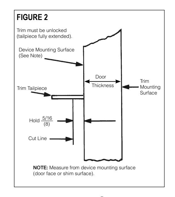
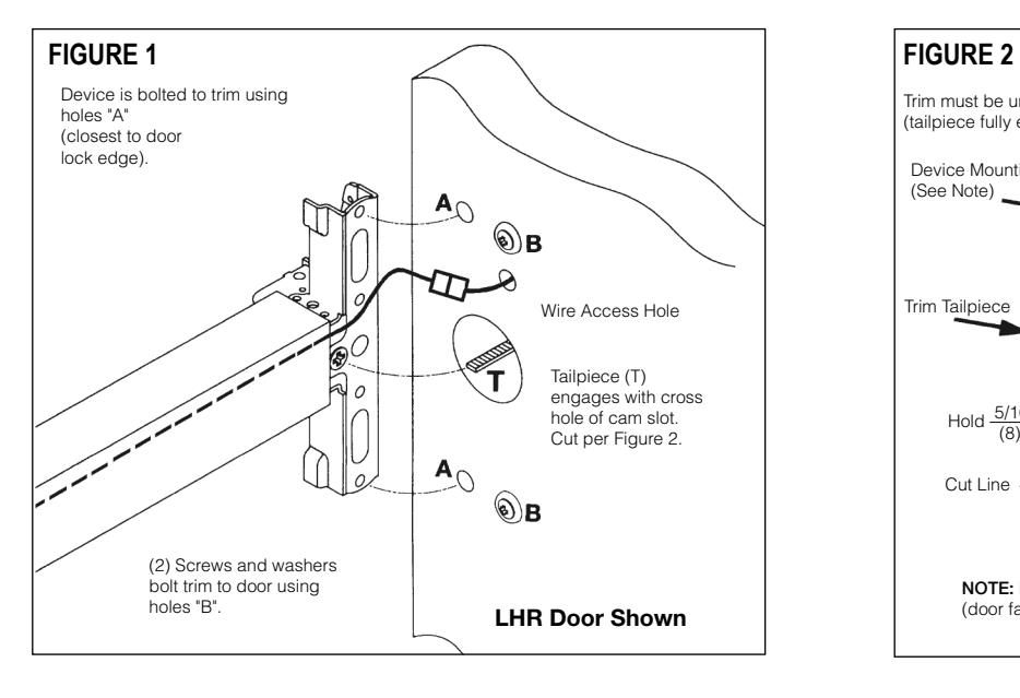
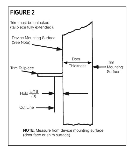
2. Doors with a thickness larger than 1-3/4" (44.5) requires a larger tailpiece.
Refer to Corbin Russwin tailpiece chart on this page.
3. Assemble cylinder.
Insert cylinder housing prongs into matching notches of escutcheon.
Pass cylinder tailpiece thru cylinder collar (when required) and slot in cylinder housing cam.
Fasten cylinder in escutcheon recess or collar using (2) mounting screws.
DO NOT OVERTIGHTEN SCREWS
Copyright © 2018 Corbin Russwin, Inc., an ASSA ABLOY Group company.
For Technical Assistance call Corbin Russwin at 1-800-810-WIRE (9473)
* Represents prefix letter(s) for various lever designs.
This product can expose you to lead which is known to the state of California to cause cancer and birth defects or other reproductive harm. For more information go to www.P65warnings.ca.gov.
08/2018
| Door thickness | Tailpiece | |
|---|---|---|
| 1-3/4" | (44.5) | 789F908 (standard) |
| 2" to 2-1/4" (51 to 57) | 789F918 | |
1-1/8" (29) 1-1/4" (32) 1-1/2" (38)
** Specify finish
Corbin Russwin Tailpiece Chart
Corbin Russwin Cylinder Collar Chart Cylinder Length Collar
None 654F07 ** 654F08 **
WARNING
1
HEAVY DUTY ELECTRICALLY CONTROLLED TRIM

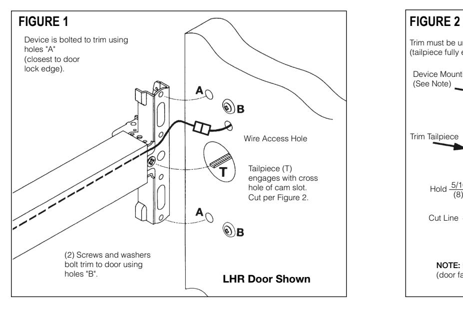
- 1. Assemble trim. See previous page for components and instructions.
- 2. After marking door inside face for device location (Device Instructions), transfer "Vertical Reference Centerline" from inside to outside door face.
Follow steps 2a. and 2b. below.
- 3. Transfer "Horizontal Reference Centerline" from inside to outside door face.
- 4. Align trim template and tape to outside door face.
- 5. Spot holes and prepare door for trim.
- 6. Pull wire through wire access hole as trim is placed in prep. To avoid wire entanglement in trim mechanism, do not leave excess wire in trim prep. Exit Device Wiring (Figure 3)
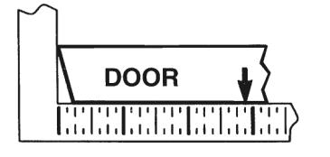
2a. MEASURE INSIDE LINE LOCATION.
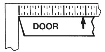
2b. TRANSFER DIMENSION
TO OUTSIDE FACE.

7. Determine power transfer method, through door or through device. For through device, see "Exit Device Wiring" below.
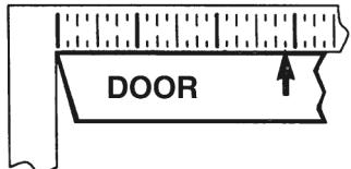
Seat device so that trim tailpiece engages with cross hole of cam slot in horizontal position as shown in Figure 1.
Continue device mounting as shown in device instructions.
Do not install covers until device is wired.
Connect trim to 4' wire harness.
Refer to Typical Wiring Instructions after device has been installed.
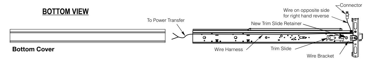
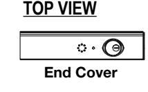
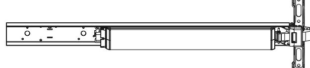
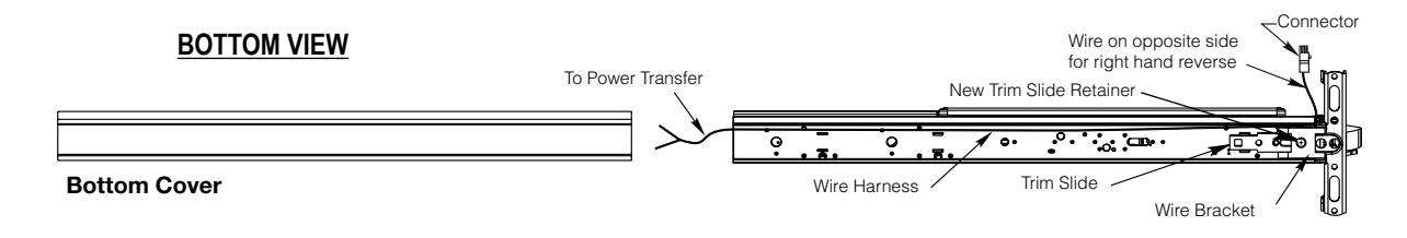
- a. Remove end cover and bottom cover.
- b. Remove trim slide retainer and replace with new retainer.
- c. Place wire bracket over new trim slide retainer, as shown.
- d. Place wire harness on the carrier with the plug connector at the latch side of the device. Allow 6" for connection to the electric trim.
Place the wire harness between the wire bracket and carrier.
e. Replace the bottom cover and end cover.


HEAVY DUTY ELECTRICALLY CONTROLLED TRIM

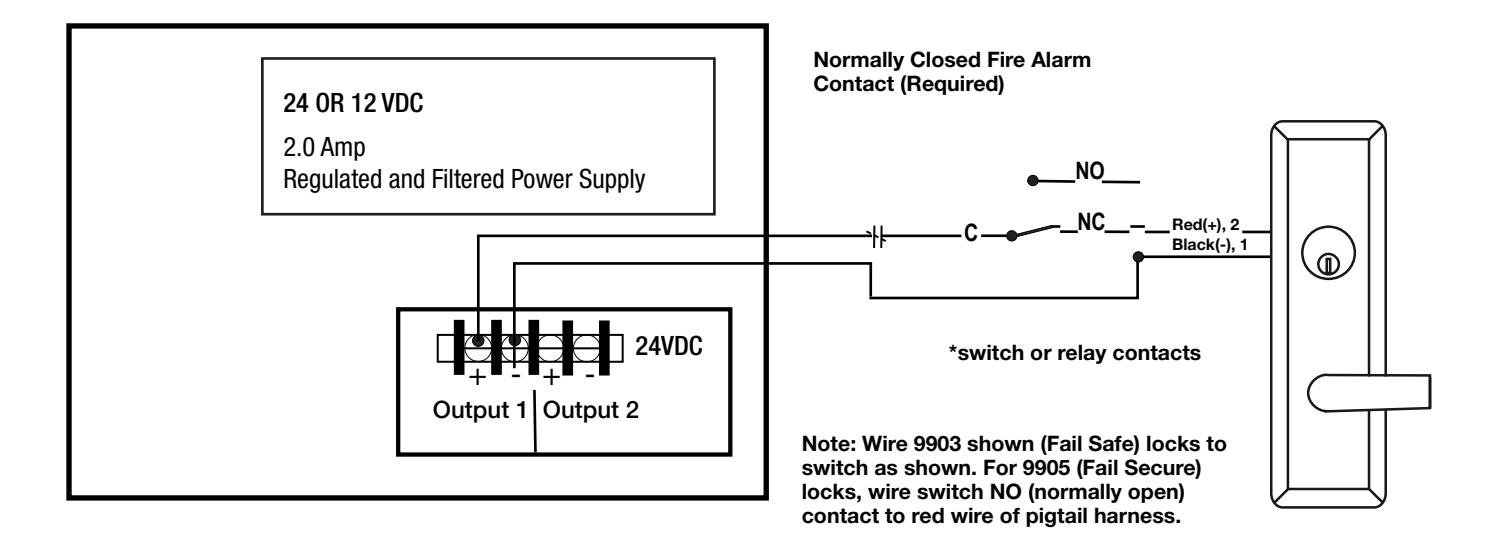
ELECTRICAL SPECIFICATIONS
DC/AC POWER LEADS
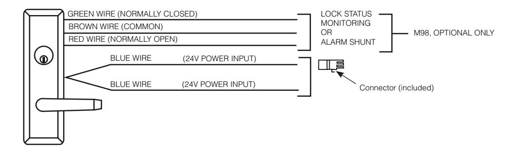
Sample wiring for 9903 & 9905 EcoFlex ET with a 24 OR 12 VDC Regulated and Filtered Power Supply
HEAVY DUTY ELECTRICALLY CONTROLLED TRIM

- 1. Assemble trim. See previous page for components and instructions.
- 2. After marking door inside face for device location (Device Instructions), transfer "Vertical Reference Centerline" from inside to outside door face.
Follow steps 2a. and 2b. below.
- 3. Transfer "Horizontal Reference Centerline" from inside to outside door face.
- 4. Align trim template and tape to outside door face.
- 5. Spot holes and prepare door for trim.
- 6. Pull wire through wire access hole as trim is placed in prep. To avoid wire entanglement in trim mechanism, do not leave excess wire in trim prep.
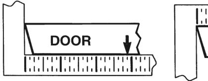
2a. MEASURE INSIDE LINE LOCATION
2b. TRANSFER DIMENSION TO OUTSIDE FACE
Mount trim to door thru holes "B", guide the tailpiece to pass thru the hole "T" - if necessary use a screw driver to guide the tailpiece. After the trim is in position, fasten by finger tightening only, with (2) screws and washers seating on door as shown in Figure 1.
7. Determine power transfer method, through door or through device. For through device, see "Exit Device Wiring" below. Seat device so that trim tailpiece engages with cross hole of cam slot in horizontal position as shown in Figure 1. Continue device mounting as shown in device instructions. Do not install covers until device is wired. Connect trim to 4' wire harness.
Refer to Typical Wiring Instructions after device has been installed.
Exit Device Wiring (Figure 3)
- a. Remove end cover and bottom cover.
- b. Remove trim slide retainer and replace with new retainer.
- c. Place wire bracket over new trim slide retainer, as shown.
- d. Place wire harness on the carrier with the plug connector at the latch side of the device. Allow 6" for connection to the electric trim.
- Place the wire harness between the wire bracket and carrier.
- e. Replace the bottom cover and end cover.


Door Marker Template
Dimensions given in ( mm ) Inches
HOLES MARKED "X" (4 Places)
METAL DOORS:
Inside Face 5/16" (8) Dia. Outside Face 1/2" (13) Dia. Thru
WOOD DOORS: 1/2" (13) Dia. Thru
OUTSIDE FACE OF DOOR Vertical Reference L (Trim Centerline) C X X X X Thru Wire Access Hole (LHR Shown, RHR Opposite) HORIZONTAL REFERENCE (CENTERLINE DEVICE AND TRIM) FM211 10/18 1-3/8" 35mm 1-3/8" 35mm 1/4" 6mm 3/4" (19mm) Ø1/2" (13mm) (92mm) 3-5/8" 2" (50.8mm) (51mm) 2" (92mm) 3-5/8" 1-3/8" 11/16" (35mm) 11/16" (17.5mm) 1" (25mm) Radius 1-1/4" (32) Deep Cutout Dia. Thru Ø1/2" (13mm) Shaded Area 5/8" 16mm 1/4" Radius x 1/4" Deep (6mm x 6mm) x2 CL
(35mm)
CAUTION: Office copiers and facsimile machines may change the size of a drawing and make the template inaccurate to use as a door marker. If this is not the original template packed with the trim, use only the dimensions written on the template to locate the holes on the door (do not use template as a door marker).
For Technical Assistance call Corbin Russwin at 1-800-810-WIRE (9473)
Copyright © 2018 Corbin Russwin, Inc., an ASSA ABLOY Group company. All rights reserved. Reproduction in whole or in part without the express written permission of Corbin Russwin, Inc. is prohibited.
Corbin Russwin 225 Episcopal Road Berlin, CT 06037 Phone: 800-543-3658 Fax: 800-447-6714 corbinrusswin.com
For Technical Assistance call Corbin Russwin at 1-800-810-WIRE (9473)