


← Corbin
INSTALLATION INSTRUCTIONS FOR 907BKM, 908BKM and 910KM MULLIONS

FM278 2/08 (617417805)
Tools Required:
- · Measuring Tape
- · Pencil
- · Drill & Tap Sizes: #7 drill and 1/4"-20 tap
- · Concrete Drill: 3/8" diameter
- · Center Punch
- · Hammer
- · #3 Phillips Screw Drivers
- · 5/64" Allen Wrench
- · 1/8" Allen Wrench
To install Mullion in frame
- 1. Close and block the doors against the frame stops. Check gap between door leaves and door to frame and correct if necessary.
-
2. Locate the center of the opening on the floor. Using the Bottom Retainer, mark the positions for the two drop-in fasteners.
- a. The bottom of the door should come to rest against the surface of the Mullion.
- b. Modify threshold as required.
- 3. Drill (2) 3/8" diameter holes in floor with cement bit to a minimum depth of 2-1/2".
- 4. Fasten Bottom Retainer to floor.
-
5. Locate the center of the opening on the top of the frame. Using the Top Retainer, mark the positions for the (4) fasteners.
- a. The door should evenly rest against both the frame stop and the Mullion.
- b. If a Top Retainer mounting kit is used, modify weather-stripping as required.
- 6. Drill and tap each location for 1/4"-20 fasteners.
- 7. Mount Top Retainer on frame with provided fasteners.
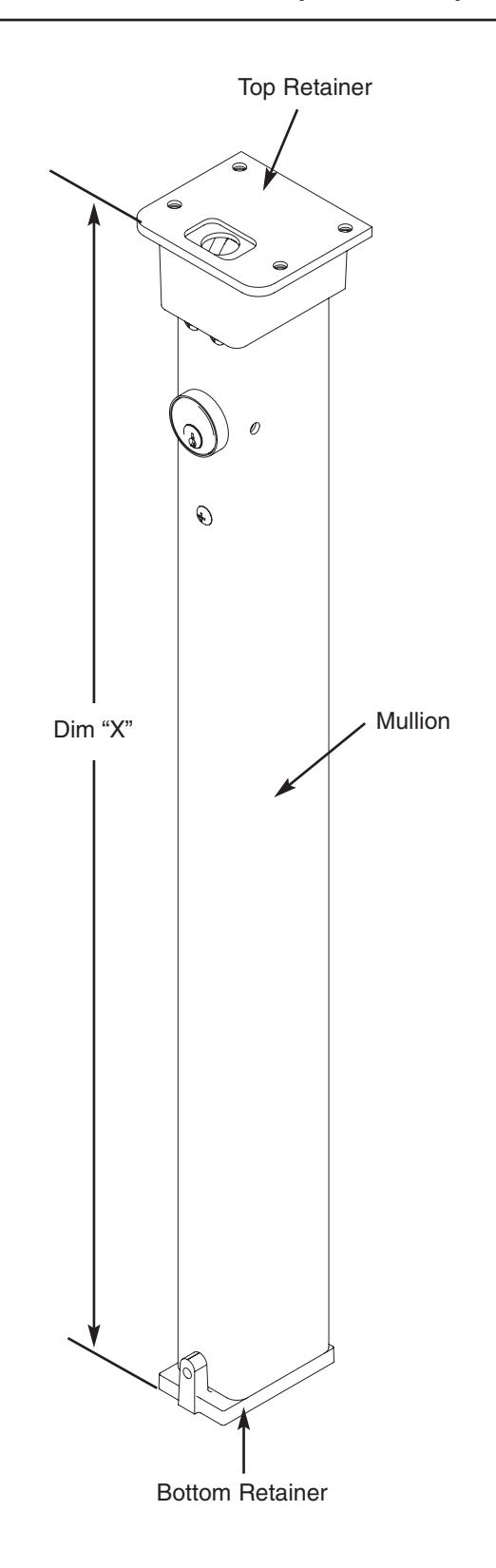
- 8. Measure "Dim X" as shown. Remove material from the bottom of the Mullion per the formula: length of Mullion = "Dim X" - 3/4". Note –This leaves approximately 1/8" clearance between the Mullion and the Top Retainer when mounted.
INSTALLATION INSTRUCTIONS FOR 907BKM, 908BKM and 910KM MULLIONS

FM278 2/08 (617417805)
-
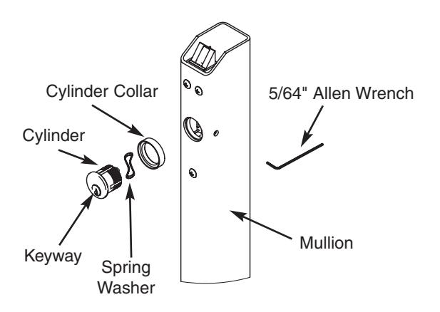
9. Installation of Cylinder
- a. Depress latchbolt and hold fully retracted.
- b. Carefully thread Cylinder with Cylinder Collar and Spring Washer into lock assembly until it bottoms out.
- c. Unscrew the Cylinder orienting keyway at bottom.
- d. Release latch bolt. Note: If latch bolt is not fully projected loosen Cylinder an additional 1-2 full turns.
- e. Tighten set screw with 5/64" Allen Wrench through access hole in side of Mullion.
- f. Check operation of Cylinder and lock assembly. Note : Key only turns counter-clockwise.
- 10. Place Mullion onto Bottom Retainer and pivot into opening to latch.
- 11. Tighten Bottom Retainer set screw to prevent Mullion rattle.
- 12. Install exit devices according to manufacturer's instructions.
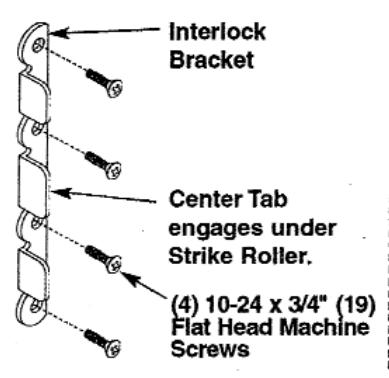
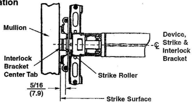
- 13. Fire rated Rim and SecureBolt® Exit Devices: After exit devices and strikes have been assembled, install Interlock Brackets with (4) #10-24 x 3/4" screws as shown in illustration below.
Corbin Russwin, Inc. 225 Episcopal Road Berlin, CT 06037-4004 www.corbinrusswin.com
Technical Product Support
Phone: 888-607-5703 Fax: 800-659-7293
Canada: ASSA ABLOY DSS Canada 160 Four Valley Drive Vaughan, Ontario L4K 4T9 www.assaabloycanadadss.ca
Copyright © 2008 Corbin Russwin, Inc. All rights reserved. Reproduction in whole or in part without the express written permission of Corbin Russwin, Inc. is prohibited.
2