


Shim Kit
ASSA ABLOY
| Shim Kit | 557F928 | 557F938 | 557F948 | 557F958 |
|---|---|---|---|---|
| 29, LA29, LA39, 39EL, LA39EL, 39ELD, LA39ELD | 29U | 20 | 20U | |
| Davisa | 25, 25L, 25U, 25UL, 35, 35L, 35U, 35UL | 39U | 30 | 30U |
| Device |
|
| 372, LA372, 572, LA572, 572EL, LA572EL, 572ELD, LA572ELD |
U372 | 382 | U382 |
| 392, 392L, U392, U392L, 592, 592L, U592, U592L | U572 | 582 | U582 |
Important
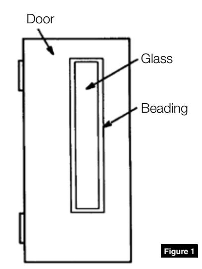
- Before mounting exit device to door with glass beading, attach shim kit as instructed.
- Always use the same number of shims for front plate, rear bracket, top and bottom latches, and rod guides.
Determine Correct Number of Shims
Measure depth of beading in door to determine number of shims needed to mount rim, mortise or vertical rod exit device. Use one shim for each 1/8" (3.18mm) of thickness. (Figure 1)
| Door | Maximum Number of Shims | |||
|---|---|---|---|---|
| Thickness | Rim & Vertical Rod Devices | Mortise Devices | ||
|
1-3/4"
(44.45mm) |
3 | 2 | ||
|
2"
(50.80mm) |
3 | 1 | ||
|
2-1/4"
(57.15mm) |
2* | 0 | ||
* with trim; 3 shims without trim
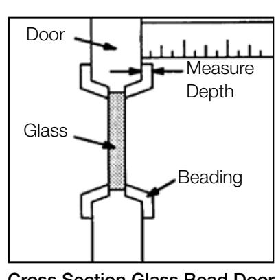
Cross Section Glass Bead Door
Installation Instructions

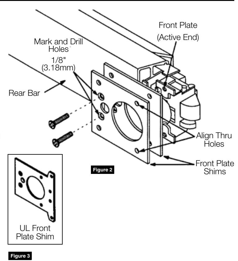
2 Mount Front Plate Shim(s) To Pushbar Device
- 1. Locate back of rear bar. Align through holes in front plate shim(s) with holes in front plate using mounting screw of Phillips screwdriver as aligning pin. Mark rear bar for two (2) holes using shim(s) as a template. Drill two (2) 1/8" (3.18mm) diameter holes into rear bar where marked.
- 2. Position desired number of front plate shims with countersinks facing out over holes. Insert flat head self-tapping screws provided through shims into holes in rear bar. Tighten screws securely so that screw heads are flush. (Figure 2)
NOTE: For UL Exit Device use UL Front Plate Shim(s). (Figure 3)
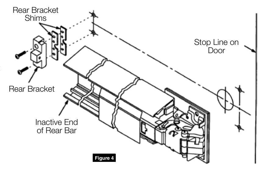
3 Mount Pushbar Device To Door
- 1. Position rear bracket over rear bracket shim(s). Insert screws provided with kit through holes in rear bracket and shim(s), but do not tighten. Be sure to use the same number of rear bracket shims as front plate shims previously installed on rear bar.
- 2. Position inactive end of rear bar between rear bracket and rear bracket shim(s). Fasten pushbar to door following exit device installation instructions for proper mounting. Tighten screws in rear bracket securely. (Figure 4)
Installation Instructions

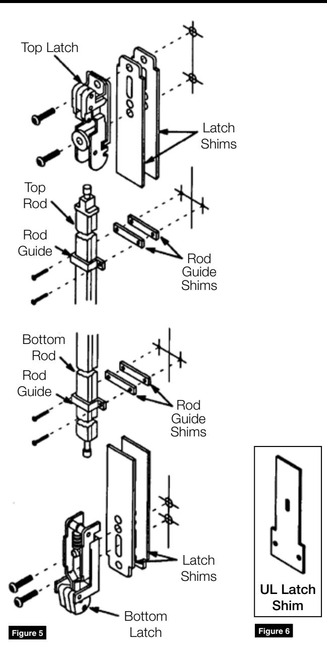
4 Mount Top/Bottom Latches and Rod Guides (Vertical Rod Exit Devices Only)
- 1. Position correct number of shims under top and bottom latches and rod guides. (Figure 5) Follow exit device installation instructions for proper mounting screws and locations. Insert screws provided with kit through holes in latches and shim(s).
- 2. Fasten top and bottom latches, as well as rod guides through shim(s) to door. Tighten all screws securely.
NOTE: For UL Device use UL Latch Shims. (Figure 6)
5 Complete Installation
Complete exit device mounting by following exit device installation instructions.
NOTE: Strike(s) must be mounted and adjusted for shim(s) used.

Corbin Russwin 225 Episcopal Road Berlin, CT 06037 Phone: 800-543-3658 Fax: 800-447-6714 corbinrusswin.com
Copyright © 2018 Corbin Russwin, Inc., an ASSA ABLOY Group company. All rights reserved. Reproduction in whole or in part without the express written permission of Corbin Russwin, Inc. is prohibited.