


ASSA ABLOY ACCENTRA™ M200FWS and Corbin Russwin FE772A / FE708A Mullions
1 Installation
Tools Required: Measuring Tape, Pencil, Drill & Tap Sizes #7 drill and 1/4"-20 tap, Concrete Drill 3/8" diameter, 1/2" Drill Punch, Hammer, #3 Phillips Screwdriver
Attention: Before starting the installation make sure that you have the correct product, and that the doors are properly installed and hinge screws are secure.
- 1. Attach the top retainer to the top jamb.
- a. Mark the centerline of the top retainer on the top jamb.
- b. Close the doors and keep door leaves tight to the stops.
- c. Fold the supplied template 80-7401-0206-000 along the creased line and locate it on the top jamb using the center line marked. Attach it to the frame and doors with self adhesive strips supplied.
- d. Mark drill and tap holes required.
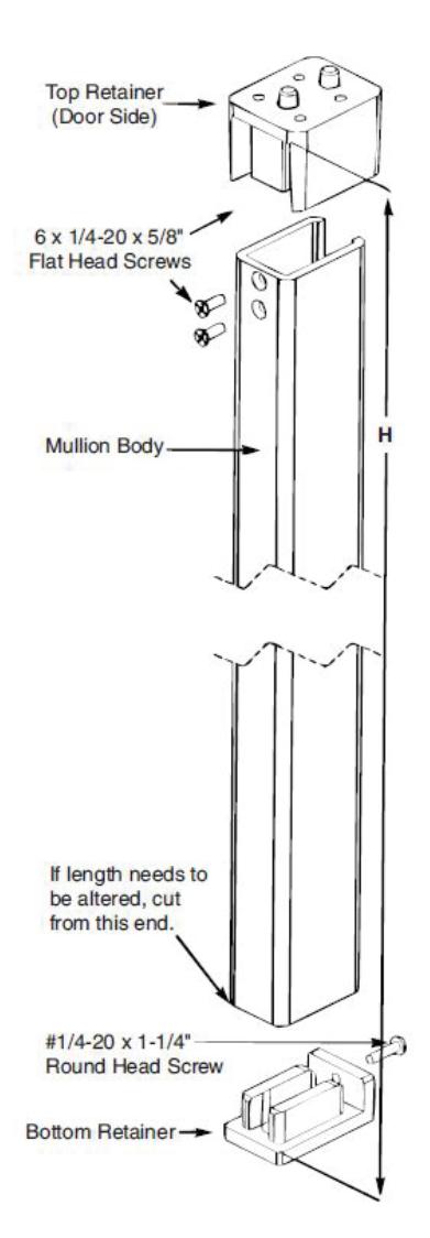
- e. Install the top retainer using (4) four 1/4-20 x 5/8" fl at head screws.
- 2. Locate the bottom retainer on the fl oor.
Attention: Do NOT attach the retainer to the fl oor at this point.
- 3. Cut the mullion body to size.
- a. Measure the distance (H) between the inside surface of the top retainer and the top of the bottom retainer surface as shown.
- b. Cut off bottom of the mullion body to desired length (L) using the following formula L = H - 1/16" (1.6)
- 4. Position the mullion body into the bottom and top retainers and locate it vertically. Mark the bottom retainer location on the fl oor (Bottom retainer still free to move).
Attention: The mullion surface must be engaged with the doors and the mullion is plumb to door face and frame.

1 Installation, continued
- 5. Install the bottom retainer.
- a. Remove the mullion body from the retainers and put it aside.
- b. Align bottom retainer with previous markings from Step 4.
- c. Use a punch and hammer to mark hole locations on fl oor.
- d. Drill (2) 3/8" (9.5) dia. holes in fl oor to a min. depth of 2-5/8" (66.7).
- e. Mount the bottom retainer to the fl oor with supplied (2) 3/8" fasteners.
- 6. Install the mullion body.
- a. Position the mullion body fi rst into the bottom retainer, then the top retainer.
- b. Drill and tap two 1/4-20 holes in the top retainer thru the countersunk holes in the mullion body.
- c. Install two 1/4-20 x 5/8" fl at head screws.
- d. Drill and tap one 1/4-20 hole in the bottom end of the mullion body thru the hole in the bottom retainer.
- e. Install one 1/4-20 x 1-1/4" round head screw.
- 7. Install exit devices according to manufacturer's instructions.
- 8. Fire rated Rim and SquareBolt® / SecureBolt® Exit Devices:
After exit devices and strikes have been assembled, install interlock brackets with #10-24 x 3/4" screws as shown in the illustration below.


ASSA ABLOY Opening Solutions 110 Sargent Drive New Haven, CT 06511 USA

This product can expose you to lead which is known to the state of California to cause cancer and birth defects or other reproductive harm. For more information go to www.P65warnings.ca.gov.