


Installation Instructions

ASSA ABLOY ACCENTRA™ KRM200 & KRM200F and Corbin Russwin CR972BKM / CR972KM / CR910BKM Mullions
1 Installation
Attention Installer
Any retrofi t or other fi eld modifi cation to a fi re rated opening can potentially impact the fi re rating of the opening, and ASSA ABLOY makes no representations or warranties concerning what such impact may be in any specifi c situation. When retrofi tting any portion of an existing fi re rated opening, or specifying and installing a new fi re-rated opening, please consult with a code specialist or local code offi cial (Authority Having Jurisdiction) to ensure compliance with all applicable codes and ratings.
Tools Required: Measuring Tape, Pencil, Drill & Tap Sizes #7 drill and 1/4"-20 tap, Concrete Drill 3/8" diameter, Center Punch, Hammer, #3 Phillips Screwdrivers, 5/32" Allen Wrench, 1/8" Allen Wrench
- 1. Close and block doors against frame stops. Check gap between door leaves and door to frame and correct if necessary.
- 2. Locate the center of the opening on the fl oor. Using the bottom retainer, mark the positions for the two drop-in fasteners.
- a. The bottom of the door should come to rest against the surface of the mullion.
- b. Modify threshold as required.
- 3. Drill holes with 3/8" diameter cement bit to a minimum depth of 2-1/2" (63.5).
- 4. Fasten bottom retainer to fl oor.
- 5. Locate the center of the opening on the top of the frame. Using the top retainer, mark the positions for the four fasteners.
- a. The door should evenly rest against both the frame stop and the mullion.
- b. If a top retainer mounting kit is used, modify weather stripping as required.
- 6. Drill and tap each location for 1/4"-20 fasteners.
- 7. Mount top retainer on frame with provided fasteners.
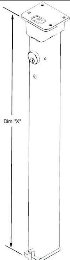
- 8. Measure "Dim X" as shown. Remove material from the bottom of the mullion per the formula length of mullion = "dim X" minus 3/4" (19mm).
Note: This leaves approximately 1/8" (3.2mm) clearance between the mullion and the top retainer when mounted.

1 Installation, continued
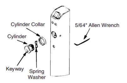
- 9. Installation of Cylinder
- a. Depress latchbolt and hold fully retracted.
- b. Carefully thread cylinder with cylinder ring into lock assembly until it bottoms out.
- c. Unscrew the cylinder orienting keyway at bottom.
- d. Release latch bolt. Note: If latch bolt is not fully projected, loosen cylinder an additional 1-2 full turns.
- e. Tighten set screw with 5/64" allen Wrench through acess hole in side of mullion.
- 10. Place mullion onto bottom bracket and pivot into opening to latch.
- 11. Tighten bottom bracket set screw to prevent mullion rattle.
- 12. Install exit devices according to the manufacturer's instructions.
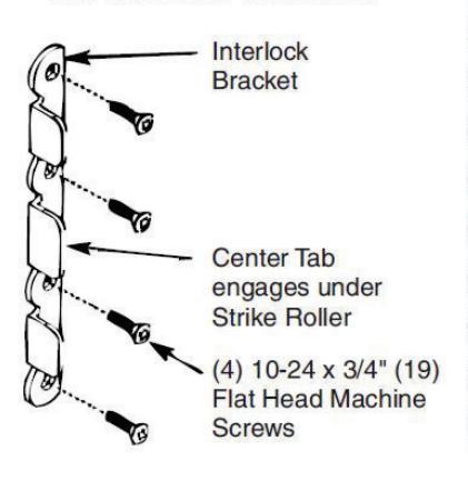
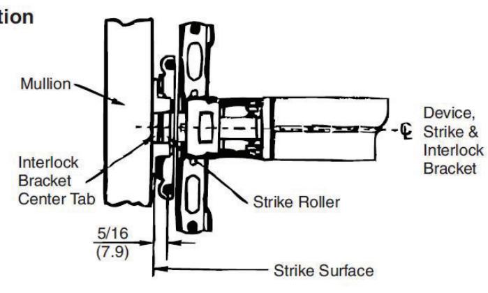
- 13. Fire rated Rim and SquareBolt® / SecureBolt® Exit Devices: After exit devices and strikes have been assembled, install interlock brackets with #10-24 x 3/4" screws as shown in the illustration below.

ASSA ABLOY Opening Solutions 225 Episcopal Road Berlin, CT 06037

This product can expose you to lead which is known to the state of California to cause cancer and birth defects or other reproductive harm. For more information go to www.P65warnings.ca.gov.