abh_a240_full_specs
Open the original PDF document
View PDF

Geared Hinge
Standard Features:
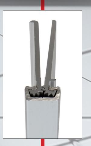
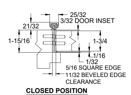
- Full Concealed, Heavy Duty
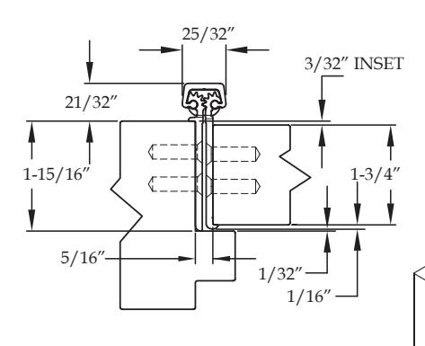
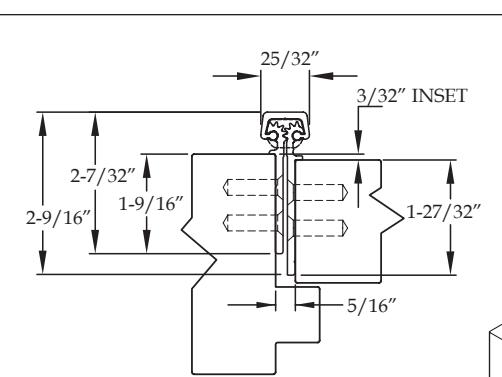
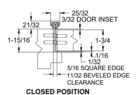
- 3/32" Door Inset
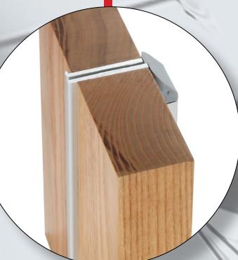
- Door Edge Protection Lip
- For use on 1-3/4" Thick Door
- 48" Door Width Maximum
- 450 lbs. Door Weight Maximum
- "LL" Model for doors up to 1000 lbs. (lead-lined staggered hole pattern)
Fasteners:
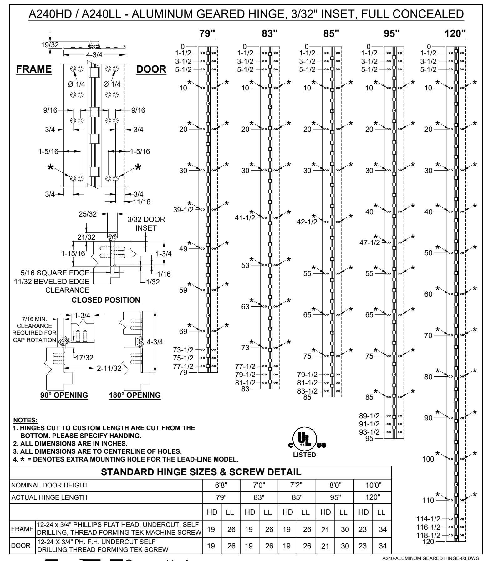
• 12-24 x 3/4" Undercut Self-Drilling, Thread-forming Tek machine screws.
Standard Lengths:
• 79", 83", 85", 95" and 120"
Finishes:
- Clear Anodized Stocked
- Dark Bronze Anodized Stocked
- Black Anodized Stocked
- Champagne
- Light Bronze
- Medium Bronze
- * Custom Powder Coating Available
Fire Rating:
- Approved for use on metal swinging type fire doors rated up to and including 90 minutes (Specify " FR " option for 3 hour rating)
- Approved for use on wood swinging type fire doors rated up to and including 60 minutes (Specify " FR " option for 90 minute rating)

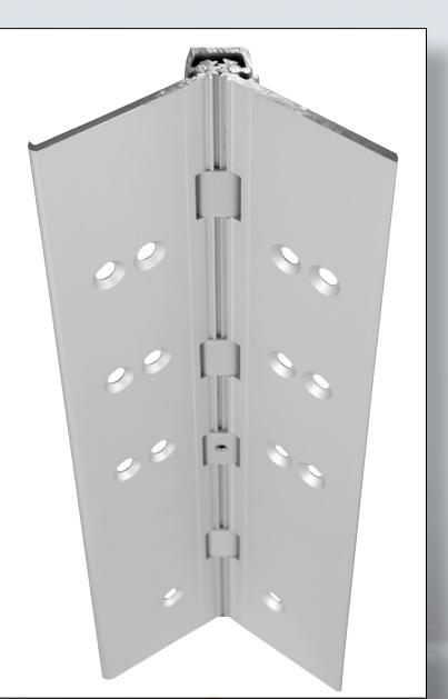
Aluminum Continuous Geared Hinges

Full Concealed
Standard Features
- Full concealed, heavy duty
- door inset
- Door edge protection lip
- For use on 1-¾" thick door
- 48" door width maximum
- 450 lbs. door weight maximum
- " LL " model for doors up to 1,000 lbs. (lead-lined staggered hole pattern)
- • Fasteners : 12-24 x ⅞" undercut self-drilling, thread-forming tek machine screws
- • Standard lengths : 79", 83", 85", 95" and 120"
- • Finishes : Clear, dark bronze and black anodized
-
• Fire Rating
- Approved for use on metal swinging type minutes (Specify " FR " option for 3 hour rating)
- Approved for use on wood swinging 60 minutes (Specify " FR " option for 90 minute rating)
Options Available
• See pages F-7 to F-8 for option availability and details
A260 HD A260 LL
Standard Features
- Full concealed, heavy duty
- door inset
- For use on 2" thick door
- 48" door width maximum
- 450 lbs. door weight maximum
- " LL " model for doors up to 1,000 lbs. (lead-lined staggered hole pattern)
- • Fasteners : 12-24 x ⅞" undercut self-drilling, thread-forming tek machine screws
- • Standard lengths : 79", 83", 85", 95" and 120"
- • Finishes : Clear, dark bronze and black anodized
-
• Fire Rating
- Approved for use on metal swinging type minutes (Specify " FR " option for 3 hour rating)
- Approved for use on wood swinging 60 minutes (Specify " FR " option for 90 minute rating)
Options Available
• See pages F-7 to F-8 for option availability and details

INSTALLATION INSTRUCTIONS FOR FULL CONCEALED HINGES
A110HD/LL, A111HD/LL, A130HD, A135HD, A140HD/LL, A150HD/LL, A160HD/LL A240HD/LL, A260HD/LL, A270HD/LL, A280HD/LL & A410HD/LL
- A. All uncut standard length hinges are non-handed and can be used for right or left hand doors.
- B. Standard length hinges are supplied slightly shorter than nominal door height to accommodate threshold and carpeting clearances.
CUTTING THE HINGE TO FIT
- · Keep hinge in the closed position
- · Determine HANDING if required. Not all hinges will become handed after cutting.
- · Cut one end of the hinge only. Cut end will be installed at the bottom (Six-hole pattern remains at the top)
- · Use a Metal Cutting Saw cut through the gear cap first.
Note: If cut length interferes with a set screw bearing remove it and switch it with a plain bearing above the cut location.
FRAME PREP
With the hinge in the open position
1. Locate the top of the hinge 1/8" below the header
With the frame leaf flange tight against the frame
2. Mark or Center Punch hole locations
Note: If using wood screws drill a 5/32" pilot hol e DO NOT ATTACH HINGE TO FRAME AT THIS TIME
ATTACH THE HINGE TO THE DOOR
- 4. Position Door Leaf on door. Door leaf alignment flange or door leaf lip must be seated against door edge.
- 5. Align the top end of the hinge to be absolutely flush with the top of the door.
- 6. Mark or Center Punch hole locations
- 7. Using the provided Self Drilling/Thread Forming Screws and the proper drive bit please proceed to attach the hinge to the door Note: If using wood screws drill a 5/32" pilot hol e.
ATTACHING DOOR TO FRAME
- 8. Position door 90 degrees to frame
- 9. Shim door to the proper height to line up the screw holes in hinge frame leaf with the marks at the top of the frame.
- 10. Install two screws at the top of the hinge to hold in place
- 11. Remove shim and align the remaining holes. Install two additional screws in the middle and at the bottom.
- 12. Check door for proper swing and clearance before installing remaining screws, making necessary adjustments.
- 13. Install the remaining fasteners after any adjustments are made.
REINFORCING AND RIVNUTS
- · No reinforcing is necessary except on extremely high-frequency, extremely heavy or extra-wide doors.
- · Rivnuts are recommended for use in the frame when the door exceeds 450lbs.
Note:RIVNUTS are not to be used with Fire Rated Hinges
PAIRS OF DOORS WITH MULLIONS
- · If the mullion is between the doors, install as single doors.
- · If the mullion is behind the doors, install as a double doors.
GROUT/SLUSHED-IN FRAMES
It is recommended that a mudguard be installed behind the frame for ease of installation. Do not use self-drill screws with grouted steel frames without a mudguard. If no mudguard has been used, drill holes through frame and remove grout for screw clearances. Do not oversize hole.
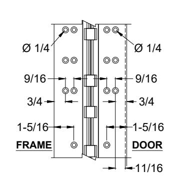
| SCREW DETAIL | |||
|---|---|---|---|
| FRAME |
12-24 x 3/4" PHILLIPS FLAT HEAD, UNDERCUT, SELF
DRILLING, THREAD FORMING TEK MACHINE SCREW |
||
| DOOR |
12-24 x 3/4" PHILLIPS FLAT HEAD, UNDERCUT, SELF
DRILLING, THREAD FORMING TEK MACHINE SCREW |
||
Note: #12 x 1-1/2" FLAT HEAD UNDERCUT WOOD SCREWS AVAILABLE UPON REQUEST
The following actions will void any warranty, expressed or implied.
- · Failure to Install the hinge according to ABH's specifications and requirements
- · Use of Fasteners other than those supplied with the hinge.
- · Unauthorized field modifications including removing any of the bearings, altering the original finish or painting the hinge.


® www.abhmfg.com
E-mail: abhinfo@abhmfg.com Architectural Builders Hardware Mfg., Inc. 1222 Ardmore Ave., Itasca, IL 60143 630.875.9900; FAX 800.9FAXABH (932.9224)
A240
ALUMINUM GEARED HINGE
© 2017 ABH Mfg., Inc. printed in USA
PAGE 1 OF 1 ISSUED 9-10-20

www.abhmfg.com E-mail: abhinfo@abhmfg.com Architectural Builders Hardware Mfg., Inc. 1222 Ardmore Ave., Itasca, IL 60143 630.875.9900; FAX 800.9FAXABH (932.9224)
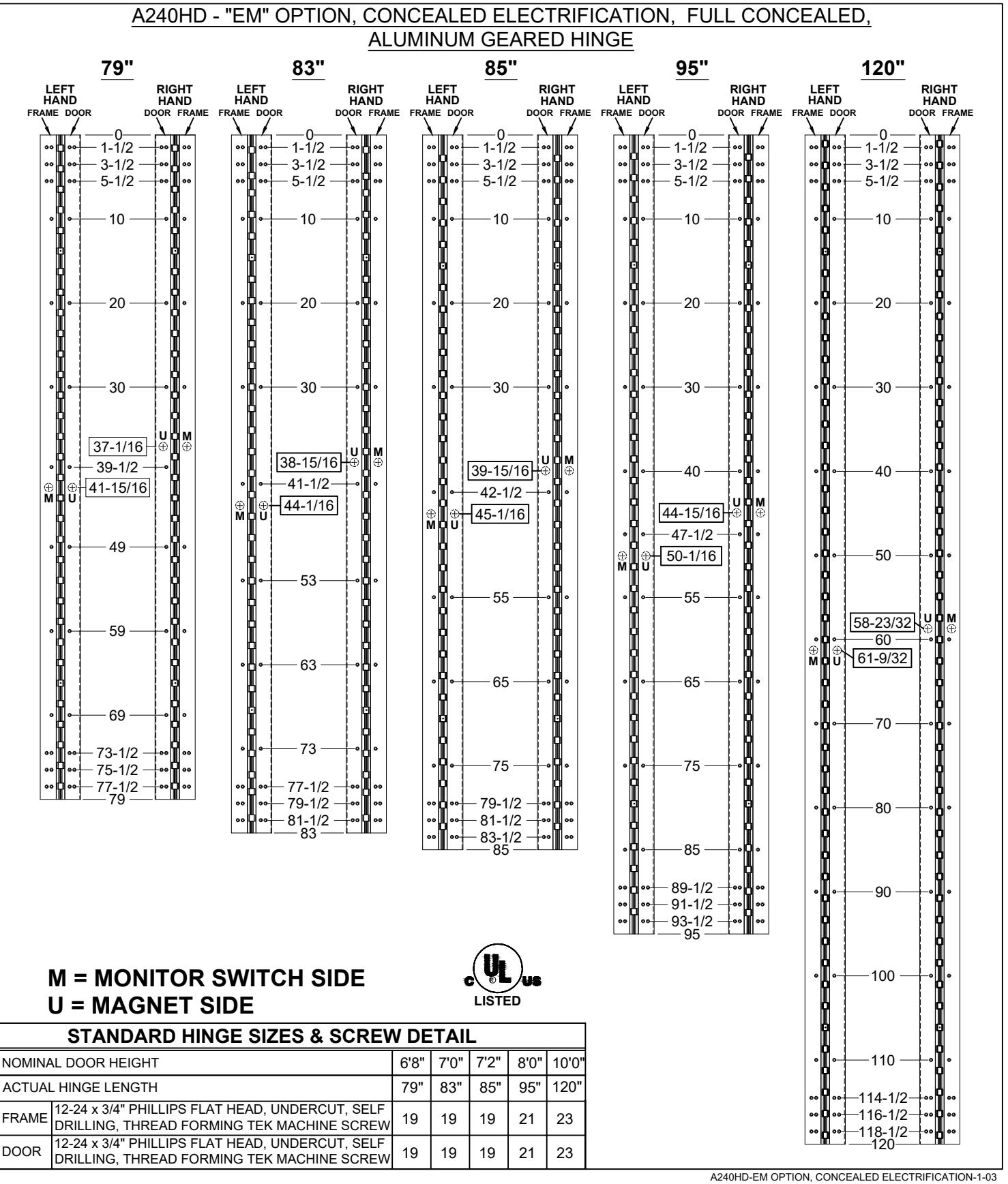
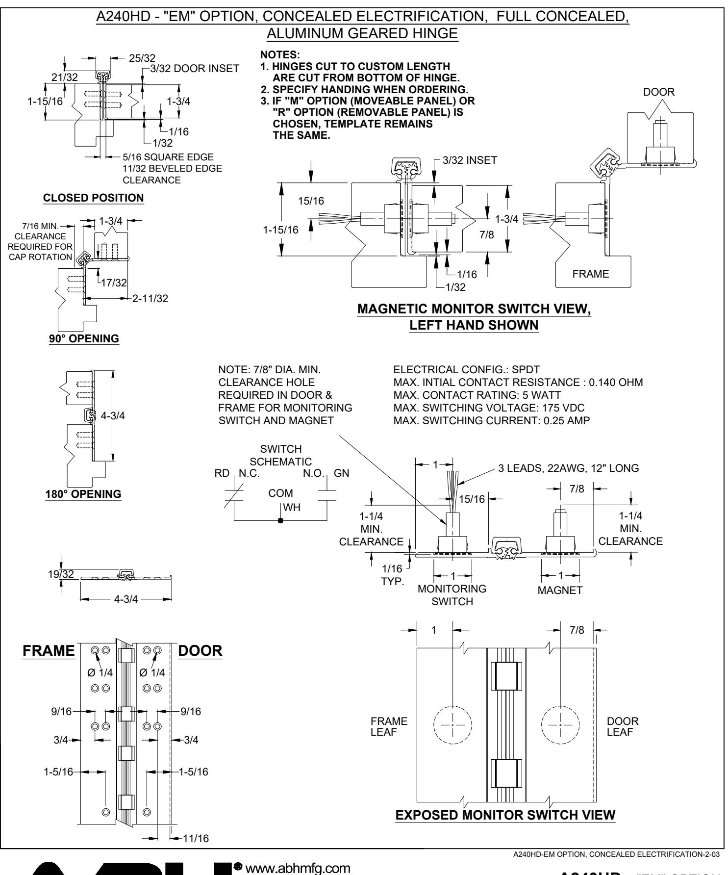
A240HD - "EM" OPTION CONCEALED ELECTRIFICATION
© 2020 ABH Mfg., Inc. printed in USA
PAGE 1 OF 2 REVISED 4-6-21

E-mail: abhinfo@abhmfg.com Architectural Builders Hardware Mfg., Inc. 1222 Ardmore Ave., Itasca, IL 60143 630.875.9900; FAX 800.9FAXABH (932.9224)
A240HD - "EM" OPTION CONCEALED ELECTRIFICATION
© 2020 ABH Mfg., Inc. printed in USA
PAGE 2 OF 2 REVISED 4-6-21
ABH* MANUFACTURING INC.
www.abhmfg.com E-mail: abhinfo@abhmfg.com Architectural Builders Hardware Mfg., Inc. 1222 Ardmore Ave., Itasca, IL 60143 630.875.9900; FAX 800.9FAXABH (932.9224)
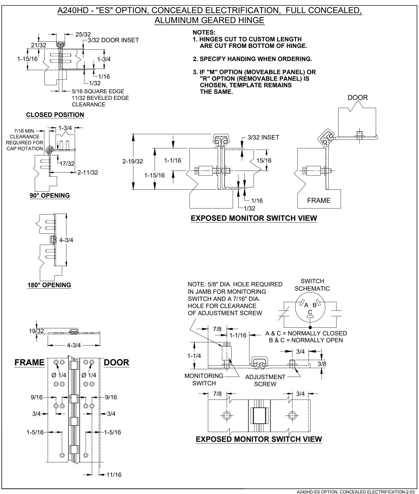
A240HD - "ES" OPTION CONCEALED ELECTRIFICATION
© 2020 ABH Mfg., Inc. printed in USA
PAGE 1 OF 2 REVISED 4-6-21

www.abhmfg.com E-mail: abhinfo@abhmfg.com Architectural Builders Hardware Mfg., Inc.
1222 Ardmore Ave., Itasca, IL 60143 630.875.9900; FAX 800.9FAXABH (932.9224)
A240HD - "ES" OPTION CONCEALED ELECTRIFICATION
© 2020 ABH Mfg., Inc. printed in USA
PAGE 2 OF 2 REVISED 4-6-21
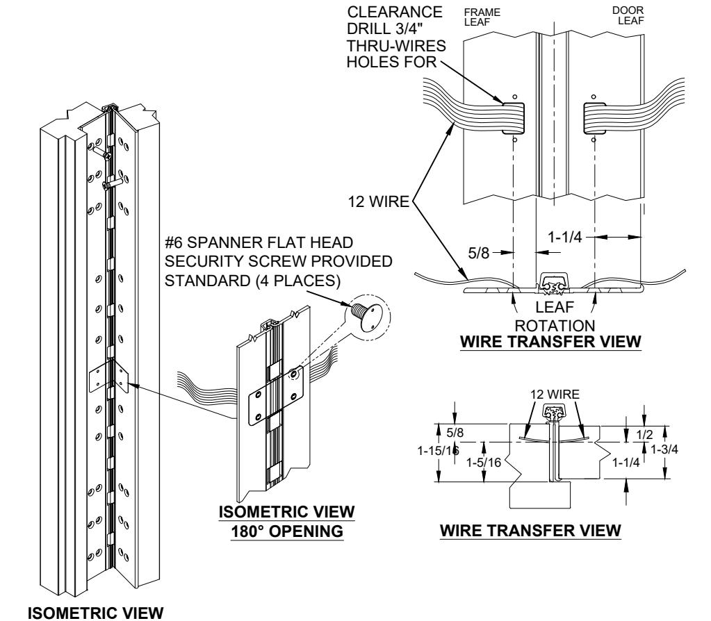
A240HD - "EA" OPTION, EASY ACCESS CONCEALED ELECTRIFICATION, ALUMINUM GEARED HINGE
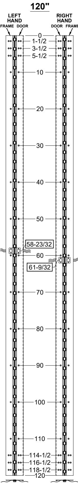
95" NON-HANDED 1-1/2 3-1/2 5-1/2 10 20 30 40 47-1/2 55 65 75 85 89-1/2 91-1/2 93-1/2 95 —
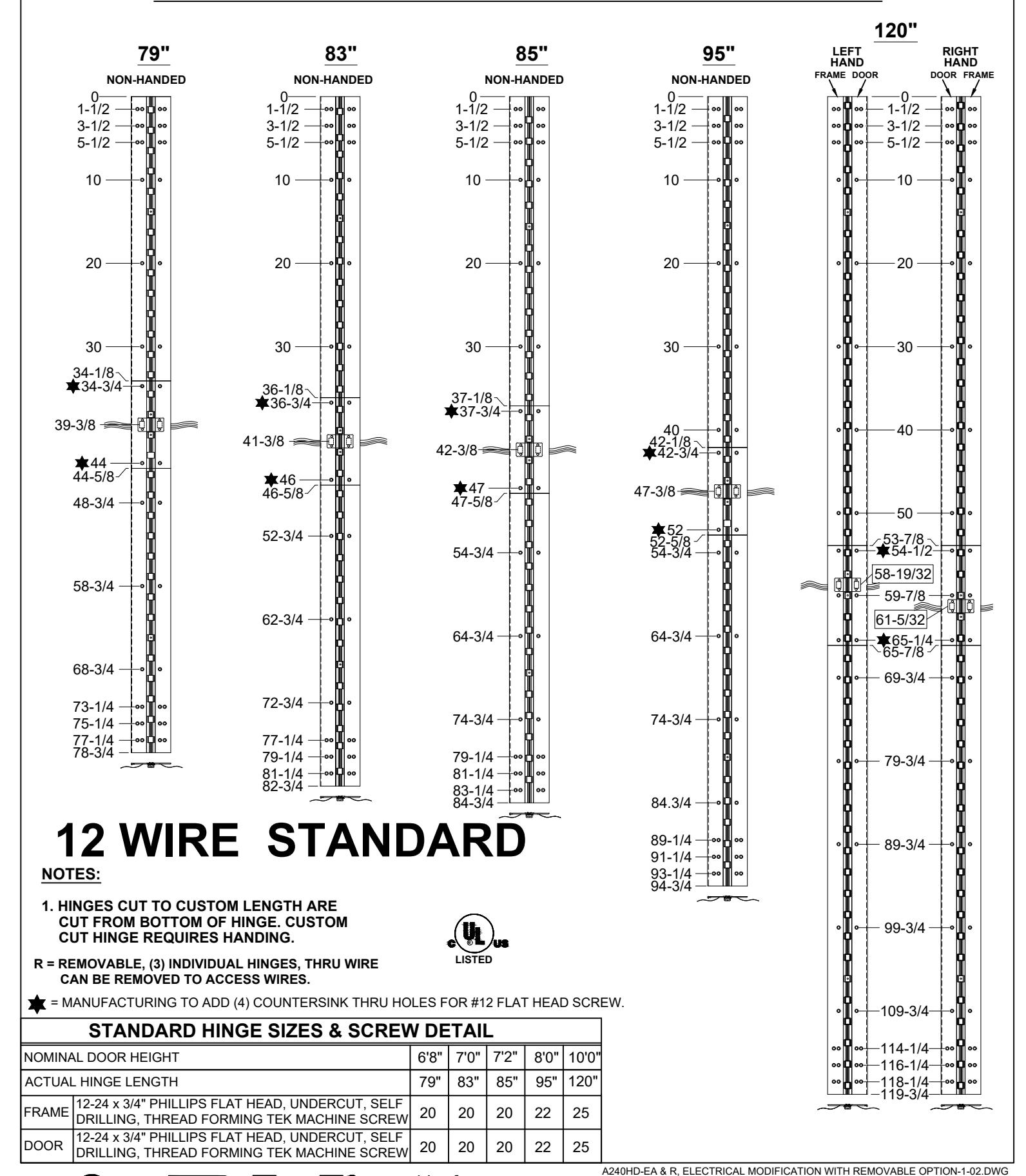
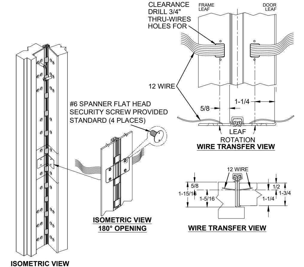
12 WIRE STANDARD
NOTES:
1. HINGES CUT TO CUSTOM LENGTH ARE CUT FROM BOTTOM OF HINGE. CUSTOM CUT HINGE REQUIRES HANDING.

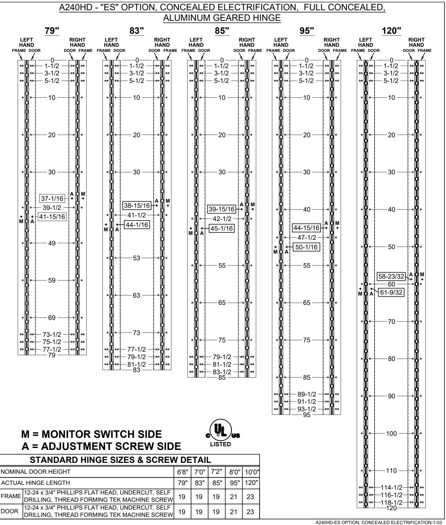
| STANDARD HINGE SIZES & SCREW DETAIL | |||||||
|---|---|---|---|---|---|---|---|
| NOMINAL DOOR HEIGHT | 6'8" | 7'0" | 7'2" | 8'0" | 10'0" | ||
| ACTUAL HINGE LENGTH | 79" | 83" | 85" | 95" | 120" | ||
| FRAME |
12-24 x 3/4" PHILLIPS FLAT HEAD, UNDERCUT, SELF
DRILLING, THREAD FORMING TEK MACHINE SCREW |
18 | 18 | 18 | 20 | 23 | |
| DOOR | 12-24 3/4" PHILLIPS FLAT HEAD, UNDERCUT, SELF DRILLING, THREAD FORMING TEK MACHINE SCREW | 18 | 18 | 18 | 20 | 23 | |
A240HD-EA OPTION, EASY ACCESS CONCEALED ELECTRIFICATION-1-03
A240HD - "EA" OPTION EASY ACCESS CONCEALED ELECTRIFICATION
E-mail: abhinfo@abhmfg.com Architectural Builders Hardware Mfg., Inc. 1222 Ardmore Ave., Itasca, IL 60143 630.875.9900; FAX 800.9FAXABH (932.9224)
© 2020 ABH Mfg., Inc. printed in USA
PAGE 1 OF 2 REVISED 4-6-21
A240HD - "EA" OPTION, EASY ACCESS CONCEALED ELECTRIFICATION, ALUMINUM GEARED HINGE
NOTES:
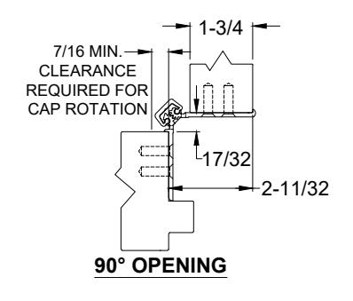
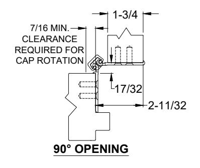
~90° OPENING
-
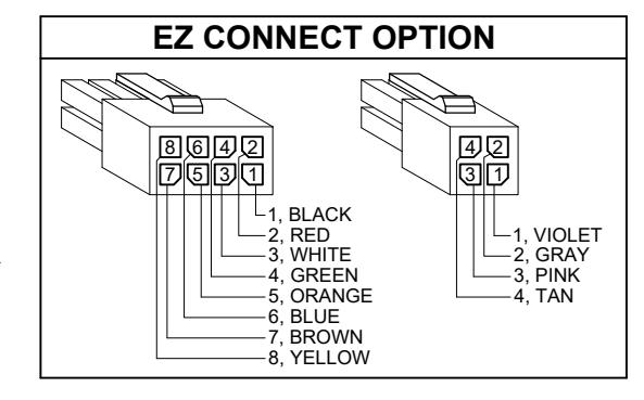
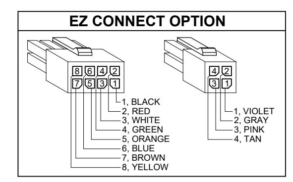
MOLEX CONNECTOR OPTION AVAILABLE - SUFFIX "EZ".
- * SPECIFY ELECTRIFIED HARDWARE MANUFACTURER FOR CONNECTOR COMPABILITY
SPECIFICATION:
DESCRIPTION: SINGLE CONDUCTOR #22 AWG MINIATURE HOOK-UP
WIRE FOR APPLICATIONS REQUIRING EXTREME FLEXIBILITY.
CONDUCTOR: #22 AWG 168/44 (0.002") SOFT BARE COPPER LHL.
INSULATION: PROPRIETARY FORMULATION PVC 0.010" NOM. WALL MEETS
VW-1 FLAME REQUIREMENT.
DIAMETER: .
RESISTANCE: 16.7 OHMS MAX. @ 20°C, PER 1000 FT.
VOLTAGE RATING: 600 VOLTS RMS, DEPENDING ON SPECIFICATION.
AVAILABLE AS ROHS COMPLIANT.
MANUFACTURING INC.
www.abhmfg.com E-mail: abhinfo@abhmfg.com Architectural Builders Hardware Mfg., Inc. 1222 Ardmore Ave., Itasca, IL 60143 630.875.9900; FAX 800.9FAXABH (932.9224)
A240HD-EA OPTION, EASY ACCESS CONCEALED ELECTRIFICATION-2-03
A240HD - "EA" OPTION EASY ACCESS CONCEALED ELECTRIFICATION
© 2020 ABH Mfg., Inc. printed in USA
PAGE 2 OF 2 REVISED 4-6-21
A240HD - "EA" & "R" ELECTRICAL MODIFICATION WITH REMOVABLE OPTION

www.abhmfg.com
E-mail: abhinfo@abhmfg.com Architectural Builders Hardware Mfg., Inc. 1222 Ardmore Ave., Itasca, IL 60143 630.875.9900; FAX 800.9FAXABH (932.9224)
A240HD - "EA" & "R" ELECTRICAL MODIFICATION
WITH REMOVABLE OPTION © 2020 ABH Mfg., Inc. printed in USA
PAGE 1 OF 2 REVISED 4-5-21
A240HD - "EA" & "R" ELECTRICAL MODIFICATION WITH REMOVABLE OPTION
NOTES:
~90° OPENING
-
1. MOLEX ® CONNECTOR OPTION
AVAILABLE - SUFFIX "EZ".
- * SPECIFY ELECTRIFIED HARDWARE MANUFACTURER FOR CONNECTOR COMPABILITY
SPECIFICATION:
DESCRIPTION: SINGLE CONDUCTOR #22 AWG MINIATURE HOOK-UP
WIRE FOR APPLICATIONS REQUIRING EXTREME FLEXIBILITY.
CONDUCTOR: #22 AWG 168/44 (0.002") SOFT BARE COPPER LHL.
PROPRIETARY FORMULATION PVC 0.010" NOM. WALL MEETS INSULATION:
VW-1 FLAME REQUIREMENT.
DIAMETER: 0.053" ± 0.003".
RESISTANCE: 16.7 OHMS MAX. @ 20°C, PER 1000 FT.
VOLTAGE RATING: 600 VOLTS RMS, DEPENDING ON SPECIFICATION.
AVAILABLE AS ROHS COMPLIANT.
MANUFACTURING INC. 630.875.9900; FAX 800.9FAXABH (932.9224)
🖲 www.abhmfg.com
E-mail: abhinfo@abhmfg.com Architectural Builders Hardware Mfg., Inc. 1222 Ardmore Ave., Itasca, IL 60143
A240HD-EA & R, ELECTRICAL MODIFICATION WITH REMOVABLE OPTION-1-02.DWG A240HD - "EA" & "R"
ELECTRICAL MODIFICATION WITH REMOVABLE OPTION
© 2020 ABH Mfg., Inc. printed in USA
PAGE 2 OF 2 REVISED 4-5-21