abh_A410_HD_full_specs
Open the original PDF document
View PDFAluminum Continuous Geared Hinges

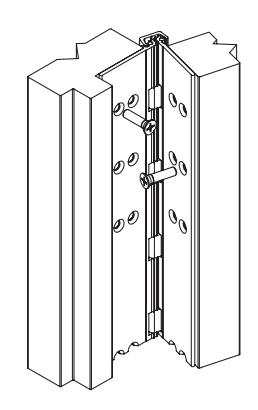
Full Concealed
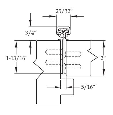
A270 HD A270 LL
Standard Features
- Full concealed, heavy duty
- •
- For use on 2" thick door
- 48" door width maximum
- 450 lbs. door weight maximum
- " LL " model for doors up to 1,000 lbs. (lead-lined staggered hole pattern)
- • Fasteners : 12-24 x ⅞" undercut self-drilling, thread-forming tek machine screws
- • Standard lengths : 79", 83", 85", 95" and 120"
- • Finishes : Clear, dark bronze and black anodized
-
• Fire Rating
- Approved for use on metal swinging type minutes (Specify " FR " option for 3 hour rating)
- Approved for use on wood swinging 60 minutes (Specify " FR " option for 90 minute rating)
Options Available
• See pages F-6 – F-8 for option availability and details
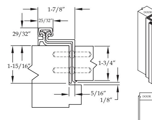
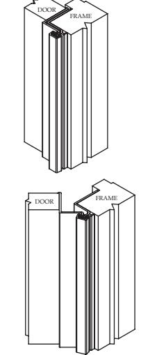
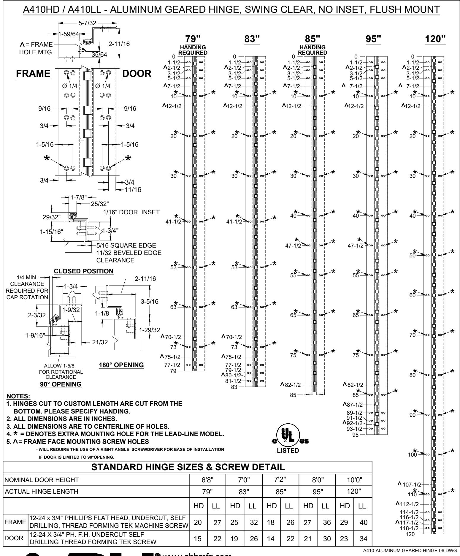
A410 HD A410 LL
Standard Features
- Full concealed, heavy duty
- •
- Swing clear application
- Door edge protection lip
- For use on 1-¾" thick door, square edged only
- 48" door width maximum
- 450 lbs. door weight maximum
- " LL " model for doors up to 1,000 lbs. (lead-lined staggered hole pattern)
- • Fasteners : 12-24 x ⅞" undercut self-drilling, thread-forming tek machine screws
- • Standard lengths : 79", 83", 85", 95" and 120"
- • Finishes : Clear, dark bronze and black anodized
-
• Fire Rating
- Approved for use on metal swinging type minutes (Specify " FR " option for 3 hour rating)
- Approved for use on wood swinging 60 minutes (Specify " FR " option for 90 minute rating)
Options Available
• See pages F-6 – F-8 for option availability and details


www.abhmfg.com E-mail: abhinfo@abhmfg.com Architectural Builders Hardware Mfg., Inc. 1222 Ardmore Ave., Itasca, IL 60143
630.875.9900; FAX 800.9FAXABH (932.9224)
A410 ALUMINUM GEARED HINGE
printed in USA
PAGE 1 OF 1 REVISED 12-20-21
UL FIRE RATED STUDS FOR INSTALLATION FULL CONCEALED ALUMINUM GEARED HINGES
MODELS A110HD/LL, A111HD/LL, A140HD/LL, A150HD/LL, A160HD/LL, A240HD/LL, A260HD/LL
FRAME
FIRE STUD
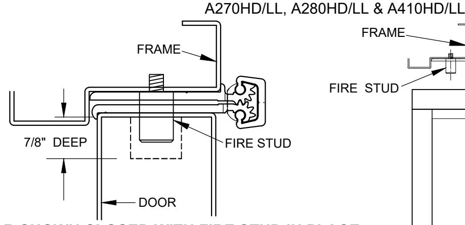
DOOR SHOWN CLOSED WITH FIRE STUD IN PLACE USING MODEL A240HD HINGE
NOTES:
- 1. INSTALL HINGE PER INSTALLATION INSTRUCTIONS FOR EACH MODEL.
- 2. FOR THE FRAME SIDE DRILL AND TAP (4) 12-24 HOLES FOR FIRE STUDS.
- 3. FOR THE DOOR SIDE DRILL (4) 3/4" DIA. HOLES IN THE DOOR TO CORRESPOND TO THE STUD HOLES IN THE FRAME SIDE.
- 4. INSERT STUDS IN THE FOUR (4) TAPPED FRAME HOLES, TIGHTEN SECURELY.
- 5. SLOWLY CLOSE DOOR MAKING SURE THAT THE STUDS ARE PROPERLY ALIGNED.
- 6. MINOR INTERFERENCE CAN BE TAKEN CARE OF WITH A ROUND METAL FILE.
|
S
O D I M E N I N |
|||||||||||
|---|---|---|---|---|---|---|---|---|---|---|---|
|
"
" A H I N G E L E N G T H |
"
9 7 |
"
8 3 |
"
8 5 |
"
9 5 |
"
1 2 0 |
||||||
|
"
" B |
"
1 2 |
"
1 2 |
"
1 2 |
"
1 2 |
"
1 2 |
||||||
|
"
" C |
"
2 5 3 / 8 - |
"
2 7 3 / 8 - |
"
2 8 3 / 8 - |
"
3 2 3 / 8 - |
"
4 2 1 / 2 - |
||||||
|
"
" D |
"
3 / 8 5 5 - |
"
/ 8 5 5 5 - |
"
6 / 8 5 5 - |
"
6 2 / 8 5 - |
"
1 / 2 7 7 - |
||||||
|
"
" E |
"
6 7 |
"
1 7 |
"
7 3 |
"
8 3 |
"
1 0 8 |
||||||
HOLES ON THE FRAME, DRILL AND TAP (4)12-24 HOLES
1/2 THE DOOR THICKNESS + 1/32" FROM CENTER OF HOLE TO EDGE OF FRAME
ALL FOUR (4) STUDS MUST BE INSTALLED TO COMPLY WITH U.L. RATING
DOOR SHOWN OPEN 180°

printed in USA www.abhmfg.com E-mail: abhinfo@abhmfg.com Architectural Builders Hardware Mfg., Inc. 1222 Ardmore Ave., Itasca, IL 60143 630.875.9900; FAX 800.9FAXABH (932.9224)
FRAME
FIRE STUD - FULL CONCEALED-03.DWG
FIRE STUD - FULL CONCEALED
DOOR
c 2021 ABH Mfg., Inc.
B
CL OF BEARING
C
DOOR
7/8" DEEP
STD. 1 8 "
CLEARANCE
1
2 DOOR THICKNESS
ON THE DOOR DRILL (4) 3
4 " DIA.
D
E
A
REVISED 11-22-21 PAGE 1 OF 1
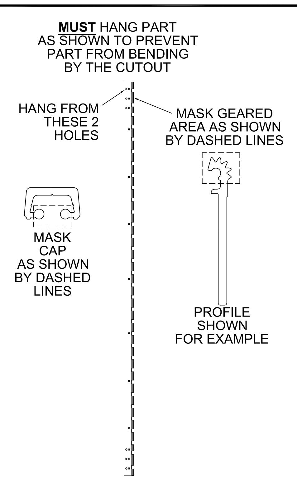
POWDER COAT MASKING

® www.abhmfg.com
E-mail: abhinfo@abhmfg.com Architectural Builders Hardware Mfg., Inc. 1222 Ardmore Ave., Itasca, IL 60143 630.875.9900; FAX 800.9FAXABH (932.9224)
POWDER COAT MASKING-00.DWG
INSTALLATION INSTRUCTIONS FOR FULL CONCEALED HINGES
A110HD/LL, A111HD/LL, A130HD, A135HD, A140HD/LL, A150HD/LL, A160HD/LL A240HD/LL, A260HD/LL, A270HD/LL, A280HD/LL & A410HD/LL
- A. All uncut standard length hinges are non-handed and can be used for right or left hand doors.
- B. Standard length hinges are supplied slightly shorter than nominal door height to accommodate threshold and carpeting clearances.
CUTTING THE HINGE TO FIT
- · Keep hinge in the closed position
- · Determine HANDING if required. Not all hinges will become handed after cutting.
- · Cut one end of the hinge only. Cut end will be installed at the bottom (Six-hole pattern remains at the top)
- · Use a Metal Cutting Saw cut through the gear cap first.
Note: If cut length interferes with a set screw bearing remove it and switch it with a plain bearing above the cut location.
FRAME PREP
With the hinge in the open position
1. Locate the top of the hinge 1/8" below the header
With the frame leaf flange tight against the frame
2. Mark or Center Punch hole locations
Note: If using wood screws drill a 5/32" pilot hol e DO NOT ATTACH HINGE TO FRAME AT THIS TIME
ATTACH THE HINGE TO THE DOOR
- 4. Position Door Leaf on door. Door leaf alignment flange or door leaf lip must be seated against door edge.
- 5. Align the top end of the hinge to be absolutely flush with the top of the door.
- 6. Mark or Center Punch hole locations
- 7. Using the provided Self Drilling/Thread Forming Screws and the proper drive bit please proceed to attach the hinge to the door Note: If using wood screws drill a 5/32" pilot hol e.
ATTACHING DOOR TO FRAME
- 8. Position door 90 degrees to frame
- 9. Shim door to the proper height to line up the screw holes in hinge frame leaf with the marks at the top of the frame.
- 10. Install two screws at the top of the hinge to hold in place
- 11. Remove shim and align the remaining holes. Install two additional screws in the middle and at the bottom.
- 12. Check door for proper swing and clearance before installing remaining screws, making necessary adjustments.
- 13. Install the remaining fasteners after any adjustments are made.
REINFORCING AND RIVNUTS
- · No reinforcing is necessary except on extremely high-frequency, extremely heavy or extra-wide doors.
- · Rivnuts are recommended for use in the frame when the door exceeds 450lbs.
Note:RIVNUTS are not to be used with Fire Rated Hinges
PAIRS OF DOORS WITH MULLIONS
- · If the mullion is between the doors, install as single doors.
- · If the mullion is behind the doors, install as a double doors.
GROUT/SLUSHED-IN FRAMES
It is recommended that a mudguard be installed behind the frame for ease of installation. Do not use self-drill screws with grouted steel frames without a mudguard. If no mudguard has been used, drill holes through frame and remove grout for screw clearances. Do not oversize hole.
|
SCREW DETAIL
12-24 x 3/4" PHILLIPS FLAT HEAD, UNDERCUT, SELF DRILLING, THREAD FORMING TEK MACHINE SCREW 12-24 x 3/4" PHILLIPS FLAT HEAD, UNDERCUT, SELF |
||||
|---|---|---|---|---|
| FRAME | ||||
| DOOR | DRILLING, THREAD FORMING TEK MACHINE SCREW | |||
Note: #12 x 1-1/2" FLAT HEAD UNDERCUT WOOD SCREWS AVAILABLE UPON REQUEST
The following actions will void any warranty, expressed or implied.
- · Failure to Install the hinge according to ABH's specifications and requirements
- · Use of Fasteners other than those supplied with the hinge.
- · Unauthorized field modifications including removing any of the bearings, altering the original finish or painting the hinge.


ABH Manufacturing Inc.
1222 Ardmore Avenue Itasca, IL 60143
Ph: (630)875-9900 Fax: (800) 932-9224
www.abhmfg.com
ANSI/BHMA A156.26-2017 Certified Continuous Hinges
Edge Mounted-Barrel Type-Stainless Steel-Grade 1
ABH Model Number(s): A500, A505, A515
Edge Mounted-Gear Type-Aluminum-Grade 1
ABH Model Number(s): A110(HD/LL), A110WT(HD/LL), A111(HD/LL), A111WT(HD/LL), A130HD, A140(HD/LL), A150(HD/LL), A160(HD/LL), A240(HD/LL), A260(HD/LL), A270(HD/LL), A410(HD/LL)
Full Surface Mounted-Barrel Type-Stainless Steel-Grade 1
ABH Model Number(s): A502, A512
Full Surface Mounted- Gear Type- Aluminum-Grade 1
ABH Model Number(s): A210HD, A570HD, A571HD
Half-Surface Mounted-Barrel Type-Stainless Steel-Grade 1
ABH Model Number(s): A503
Half-Surface Mounted- Gear Type- Aluminum-Grade 1
ABH Model Number(s): A211HD, A213HD, A450HD, A460HD, A530HD, A540HD, A550HD
Half Mortise Mounted-Barrel Type-Stainless Steel-Grade 1
ABH Model Number(s): A504, A506
Half Mortise Mounted- Gear Type- Aluminum-Grade 1
ABH Model Number(s): A520HD
Swing Clear Edge Mounted-Barrel Type-Stainless Steel-Grade 1
ABH Model Number(s): A510, A511, A526, A529
Swing Clear Edge Mounted- Gear Type- Aluminum-Grade 1
ABH Model Number(s): A410(HD/LL), A211HD
HD-denotes Heavy Duty Hinge
LL-denotes Heavy Duty hinge with extra screw holes to accommodate the lead in lead lined doors
Aluminum Continuous Geared Hinges

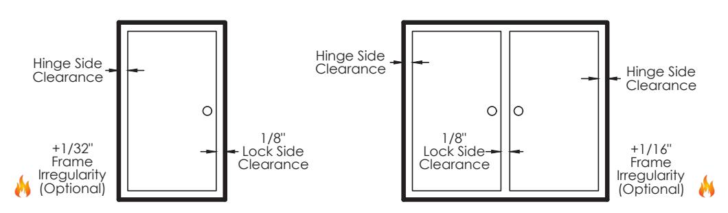
Door Clearance Chart Squared Edge
| Single Door - Squared Edged | |||||||||||
|---|---|---|---|---|---|---|---|---|---|---|---|
| Hinç |
Hinge
Thickness |
+ |
Lock Side
Clearance |
+ |
*Frame //
Irregularity (OPTIONAL) |
= |
Square Edged Door
Undersized (Single) |
||||
|
Full
Concealed |
A110, A110WT, A111
A111WT, A120,A140, A150, A160, A240, A260, A270, A410 |
5/16" | + | 1/8" | + | 1/32" | = | 15/32" | |||
| A130, A135 | 13/16" | + | 1/8" | + | 1/32" | = | 31/32" | ||||
|
Half
Surface |
A211, A213, A450, A460,
A520, A530, A540, A550 |
3/16" | + | 1/8" | + | 1/32" | = | 11/32" | |||
|
Full
Surface |
A210, A570, A571, A575 | 1/16" | + | 1/8" | + | 1/32" | = | 7/32" | |||
Single Door
Pair of Doors
| Pair of Doors - Squared Edged | |||||||||||
|---|---|---|---|---|---|---|---|---|---|---|---|
| Hing |
Hinge
Thickness (Pair) |
+ |
Lock Side
Clearance |
+ |
*Frame //
Irregularity (OPTIONAL) |
= |
Square Edged Door
Undersized (Pair) |
||||
|
Full
Concealed |
A110, A110WT, A111
A111WT, A120, A140, A150, A160, A240, A260, A270, A410 |
5/8" | + | 1/8" | + | 1/16" | = | 13/16" | |||
| A130, A135 | 1-5/8" | + | 1/8" | + | 1/16" | = | 1-13/16" | ||||
|
Half
Surface |
A211, A213, A450, A460,
A520, A530, A540, A550 |
1/4" | + | 1/8" | + | 1/16" | = | 7 / 16 " | |||
|
Full
Surface |
A210, A570, A571, A575 | 1/8" | + | 1/8" | + | 1/16" | = | 5/16" | |||
* 1/16& quot; Frame Irregularity Allowance, Optional and included in all Total Door Undersize for single and pairs of doors

Aluminum Continuous Geared Hinges

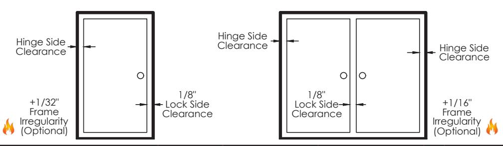
Door Clearance Chart Beveled Edge
| Single Door - Beveled Edged | |||||||||||
|---|---|---|---|---|---|---|---|---|---|---|---|
| Hinç | Hinge Model | + |
Lock Side
Clearance |
+ |
* Frame ()
Irregularity (OPTIONAL) |
+ |
Beveled
Door Clearance |
= |
Beveled
Edged Door Undersized (Single) |
||
|
Full
Concealed |
A110, A110WT, A111
A111WT, A120,A140, A150, A160, A240, A260, A270, A410 |
5/16" | + | 1/8" | + | 1/32" | + | 1/32" | = | 1/2" | |
| A130, A135 | 13/16" | + | 1/8" | + | 1/32" | + | 1/32" | = | 1" | ||
|
Half
Surface |
A211, A213, A450, A460,
A520, A530, A540, A550 |
3/16" | + | 1/8" | + | 1/32" | + | 1/32" | = | 3/8" | |
|
Full
Surface |
A210, A570, A571, A575 | 1/16" | + | 1/8" | + | 1/32" | + | N/A | = | 7/32" | |
Single Door
Pair of Doors
| Pair of Doors - Beveled Edged | |||||||||||
|---|---|---|---|---|---|---|---|---|---|---|---|
| Hinge Model |
Hinge
Thickness (Pair) |
+ |
Lock Side
Clearance |
+ |
* Frame
Irregularity (OPTIONAL) |
+ |
Beveled
Door Clearance |
= |
Beveled
Edged Door Undersized (Pair) |
||
|
Full
Concealed |
A110, A110WT, A111
A111WT, A120, A140, A150, A160, A240, A260, A270, A410 |
5/8" | + | 1/8" | + | 1/16" | + | 1/16" | = | 7 8 " | |
| A130, A135 | 1-5/8" | + | 1/8" | + | 1/16" | + | 1/16" | = | 1-7/8" | ||
|
Half
Surface |
A211, A213, A450, A460,
A520, A530, A540, A550 |
1/4" | + | 1/8" | + | 1/16" | + | N/A | = | 7/16" | |
|
Full
Surface |
A210, A570, A571, A575 | 1/8" | + | 1/8" | + | 1/16" | + | N/A | = | 5/16" | |
* 1/16& quot; Frame Irregularity Allowance, Optional and included in all Total Door Undersize for single and pairs of doors
