abh_A213_HD_full_specs
Open the original PDF document
View PDFAluminum Continuous Geared Hinges

Half Surface
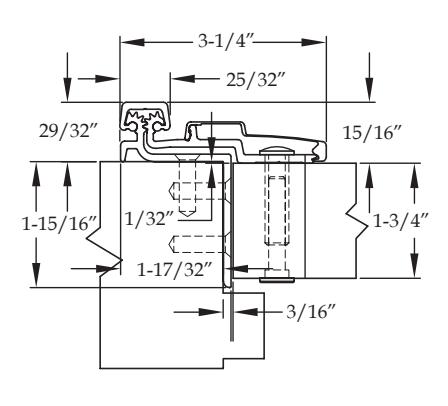
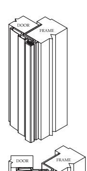
A211 HD
Standard Features
- Half surface, heavy duty
- door inset
- Swing clear application
- 48" door width maximum
- 450 lbs. door weight maximum
- • Fasteners : 12-24 x ⅞" undercut self-drilling, thread-forming tek machine screws for frame and ¼-20 sex bolts and shoulder bolts for door
- • Standard lengths : 79", 83", 85", 95" and 120"
- • Finishes : Clear, dark bronze and black anodized
-
• Fire Rating
- Approved for use on metal swinging type minutes (Specify " FR " option for 3 hour rating)
- Approved for use on wood swinging 60 minutes (Specify " FR " option for 90 minute rating)
Options Available
• See pages F-7 to F-8 for option availability and details
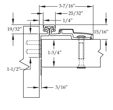
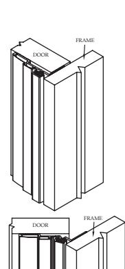
A213 HD
Standard Features
- Half surface, heavy duty
- guards require a long reach
- 48" door width maximum
- 450 lbs. door weight maximum
- • Fasteners : 12-24 x ⅞" undercut self-drilling, thread-forming tek machine screws for frame and ¼-20 sex bolts and shoulder bolts for door
- • Standard lengths : 79", 83", 85", 95" and 120"
- • Finishes : Clear, dark bronze and black anodized
-
• Fire Rating
- Approved for use on metal swinging type minutes (Specify " FR " option for 3 hour rating)
- Approved for use on wood swinging 60 minutes (Specify " FR " option for 90 minute rating)
Options Available
• See pages F-7 to F-8 for option availability and details


∣® www.abhmfg.com
E-mail: abhinfo@abhmfg.com Architectural Builders Hardware Mfg., Inc. 1222 Ardmore Ave., Itasca, IL 60143 630.875.9900; FAX 800.9FAXABH (932.9224)
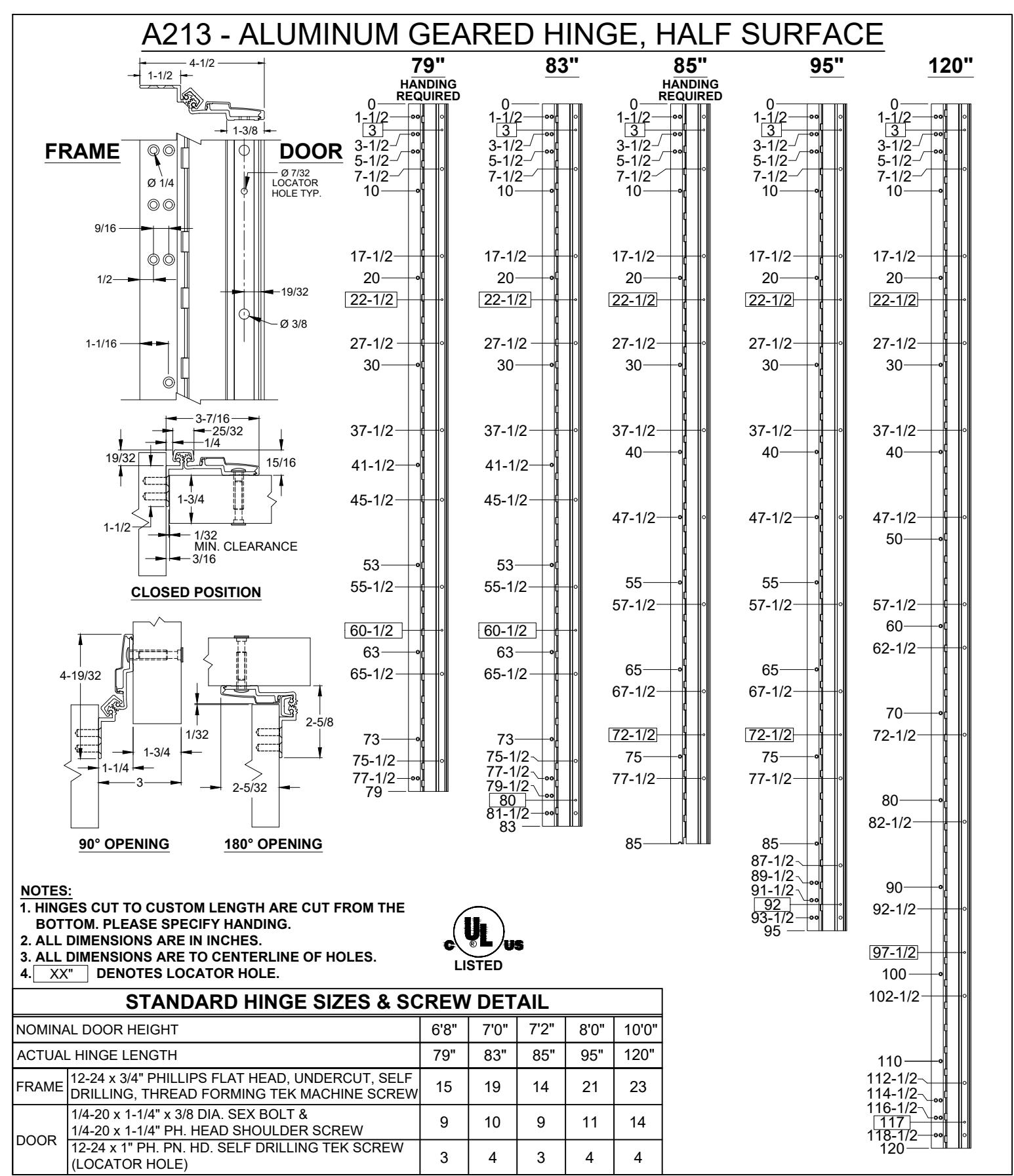
A213-ALUMINUM GEARED HINGE-02.DWG
A213 ALUMINUM GEARED HINGE
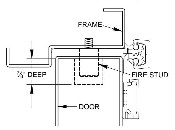
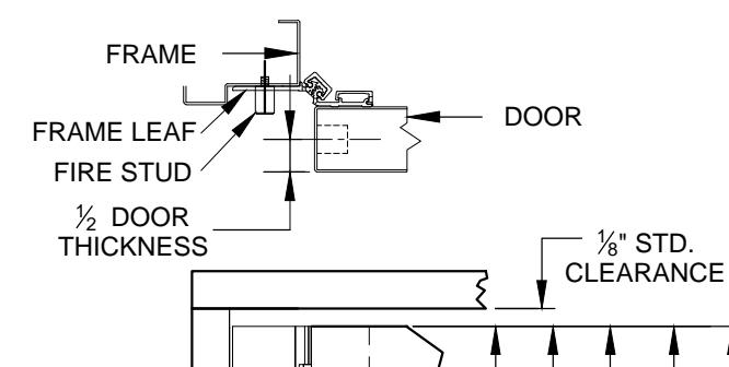
UL FIRE RATED STUDS FOR INSTALLATION HALF SURFACE ALUMINUM GEARED HINGES
MODELS A211HD, A213HD, A450HD, A460HD, A530HD, A540HD & A550HD
В
С
D
Ε
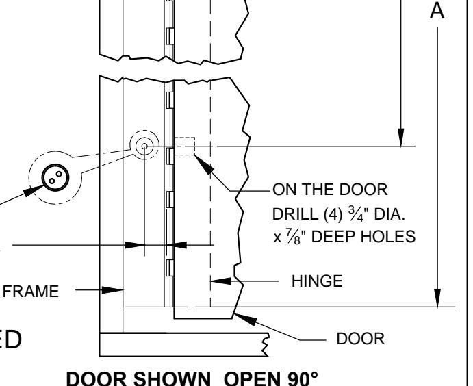
DOOR SHOWN CLOSED WITH FIRE STUD IN PLACE USING MODEL A540HD HINGE
NOTES:
- 1. INSTALL HINGE PER INSTALLATION INSTRUCTIONS FOR EACH MODEL.
- 2. FOR THE FRAME SIDE DRILL AND TAP (4) 12-24 HOLES FOR FIRE STUDS.
- 3. FOR THE DOOR SIDE DRILL (4) " DIA. HOLES IN THE DOOR TO CORRESPOND TO THE STUD HOLES IN THE FRAME SIDE.
- 4. INSERT STUDS IN THE FOUR (4) TAPPED FRAME HOLES, TIGHTEN SECURELY.
- 5. SLOWLY CLOSE DOOR MAKING SURE THAT THE STUDS ARE PROPERLY ALIGNED.
- MINOR INTERFERENCE CAN BE TAKEN CARE OF WITH A ROUND METAL FILE.
| DIMENSION | |||||||||
|---|---|---|---|---|---|---|---|---|---|
|
"A"
HINGE LENGTH |
79" | 83" | 85" | 95" | 120" | ||||
| "B" | 12" | 12" | 12" | 12" | 12" | ||||
| "C" | 25-3/8" | 27-3/8" | 28-3/8" | 32-3/8" | 42-1/2" | ||||
| "D" | 53-5/8" | 55-5/8" | 56-5/8" | 62-5/8" | 77-1/2" | ||||
| "E" | 67" | 71" | 73" | 83" | 108" | ||||
ON THE FRAME, DRILL AND TAP (4)12-24 HOLES
DOOR THICKNESS + " FROM CENTER OF HOLE TO EDGE OF FRAME
ALL FOUR (4) STUDS <u>MUST</u> BE INSTALLED TO COMPLY WITH U.L. RATING
FIRE STUD - HALF SURFACE-01.DWG
FIRE STUD -HALF SURFACE
© 2016 ABH Mfg., Inc. printed in USA
PAGE 1 OF 1 REVISED 10-05-16

www.abhmfg.com E-mail: abhinfo@abhmfg.com Architectural Builders Hardware Mfg., Inc. 1222 Ardmore Ave., Itasca, IL 60143 630.875.9900; FAX 800.9FAXABH (932.9224)
Aluminum Continuous Geared Hinges

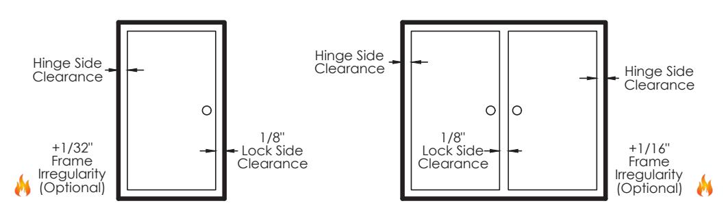
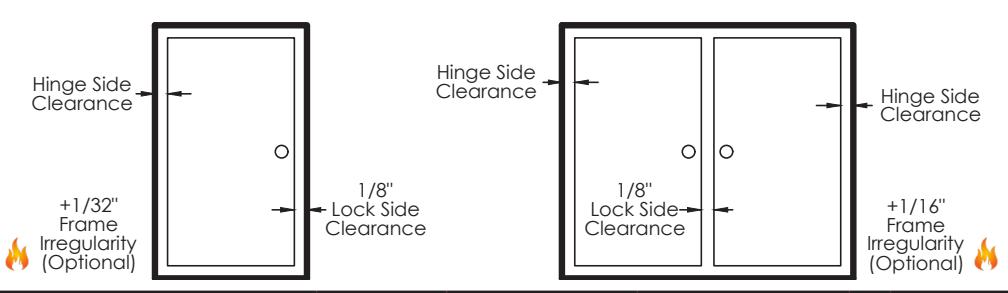
Door Clearance Chart Squared Edge
| Single Door - Squared Edged | ||||||||
|---|---|---|---|---|---|---|---|---|
| Hinge Model |
Hinge
Thickness |
+ |
Lock Side
Clearance |
+ |
*Frame //
Irregularity (OPTIONAL) |
= |
Square Edged Door
Undersized (Single) |
|
|
Full
Concealed |
A110, A110WT, A111
A111WT, A120,A140, A150, A160, A240, A260, A270, A410 |
5/16" | + | 1/8" | + | 1/32" | = | 15/32" |
| A130, A135 | 13/16" | + | 1/8" | + | 1/32" | = | 31/32" | |
|
Half
Surface |
A211, A213, A450, A460,
A520, A530, A540, A550 |
3/16" | + | 1/8" | + | 1/32" | = | 11/32" |
|
Full
Surface |
A210, A570, A571, A575 | 1/16" | + | 1/8" | + | 1/32" | = | 7/32" |
Single Door
Pair of Doors
| Pair of Doors - Squared Edged | ||||||||
|---|---|---|---|---|---|---|---|---|
| Hinge Model |
Hinge
Thickness (Pair) |
+ |
Lock Side
Clearance |
+ |
*Frame //
Irregularity (OPTIONAL) |
= |
Square Edged Door
Undersized (Pair) |
|
|
Full
Concealed |
A110, A110WT, A111
A111WT, A120, A140, A150, A160, A240, A260, A270, A410 |
5/8" | + | 1/8" | + | 1/16" | = | 13/16" |
| A130, A135 | 1-5/8" | + | 1/8" | + | 1/16" | = | 1-13/16" | |
|
Half
Surface |
A211, A213, A450, A460,
A520, A530, A540, A550 |
1/4" | + | 1/8" | + | 1/16" | = | 7 / 16 " |
|
Full
Surface |
A210, A570, A571, A575 | 1/8" | + | 1/8" | + | 1/16" | = | 5/16" |
* 1/16& quot; Frame Irregularity Allowance, Optional and included in all Total Door Undersize for single and pairs of doors

Aluminum Continuous Geared Hinges

Door Clearance Chart Beveled Edge
| Single Door - Beveled Edged | ||||||||||
|---|---|---|---|---|---|---|---|---|---|---|
| Hinç | ge Model |
Hinge
Thickness |
+ |
Lock Side
Clearance |
+ |
* Frame ()
Irregularity (OPTIONAL) |
+ |
Beveled
Door Clearance |
= |
Beveled
Edged Door Undersized (Single) |
|
Full
Concealed |
A110, A110WT, A111
A111WT, A120,A140, A150, A160, A240, A260, A270, A410 |
5/16" | + | 1/8" | + | 1/32" | + | 1/32" | = | 1/2" |
| A130, A135 | 13/16" | + | 1/8" | + | 1/32" | + | 1/32" | = | 1" | |
|
Half
Surface |
A211, A213, A450, A460,
A520, A530, A540, A550 |
3/16" | + | 1/8" | + | 1/32" | + | 1/32" | = | 3/8" |
|
Full
Surface |
A210, A570, A571, A575 | 1/16" | + | 1/8" | + | 1/32" | + | N/A | = | 7/32" |
Single Door
Pair of Doors
| Pair of Doors - Beveled Edged | ||||||||||
|---|---|---|---|---|---|---|---|---|---|---|
| Hinç | ge Model |
Hinge
Thickness (Pair) |
+ |
Lock Side
Clearance |
+ |
* Frame
Irregularity (OPTIONAL) |
+ |
Beveled
Door Clearance |
= |
Beveled
Edged Door Undersized (Pair) |
|
Full
Concealed |
A110, A110WT, A111
A111WT, A120, A140, A150, A160, A240, A260, A270, A410 |
5/8" | + | 1/8" | + | 1/16" | + | 1/16" | = | 7 8 " |
| A130, A135 | 1-5/8" | + | 1/8" | + | 1/16" | + | 1/16" | = | 1-7/8" | |
|
Half
Surface |
A211, A213, A450, A460,
A520, A530, A540, A550 |
1/4" | + | 1/8" | + | 1/16" | + | N/A | = | 7/16" |
|
Full
Surface |
A210, A570, A571, A575 | 1/8" | + | 1/8" | + | 1/16" | + | N/A | = | 5/16" |
* 1/16& quot; Frame Irregularity Allowance, Optional and included in all Total Door Undersize for single and pairs of doors

INSTALLATION INSTRUCTIONS FOR HALF SURFACE HINGES
A211HD, A213HD, A450HD, A460HD, A530HD, A540HD & A550HD
- A. All uncut standard length hinges are non-handed and can be used for right or left hand doors.
- B. Standard length hinges are supplied slightly shorter than nominal door height to accommodate threshold and carpeting clearances.
CUTTING THE HINGE TO FIT
- Keep hinge in the closed position. If necessary remove door leaf caps.
- Determine HANDING if required.
- Cut one end of the hinge only. The hinge becomes handed after cutting and must be installed with the cut end at the bottom to keep the templated hole pattern at the top.
- Use a Metal Cutting Saw cut through the gear cap first.
Note: If cut length interferes with a set screw bearing remove it and switch it with a plain bearing above the cut location.
ATTACHING THE HINGE TO THE FRAME
With the hinge in the open position
- 1. Locate the top of the hinge 1/8" below the header and hold tight against the frame.
- 2. Mark or Center Punch hole locations: two holes at the top and two at the bottom.
- 3. Using the provided Flathead Self Drilling/Thread Forming Screws please proceed to fasten the frame leaf in marked holes.
Note: If using wood screws drill a 5/32" pilot hole
PREPARE THE DOOR
- 4. Position Door in the opening and shim for proper clearances.
- 5. Align the top end of the hinge to be absolutely flush with the top of the door.
- 6. Mark the four LOCATOR HOLE locations (shown on template) using the provided small center punch.
- Using a #3 philips head bit, attach the door leaf to the door through the LOCATOR HOLES with the provided pan head screws
- 8. Remove any shims and check for proper clearances and door operation.
- 9. If door sags slightly, note amount of adjustment needed to bring door back into alignment.
DO NOT PROCEED UNTIL DOOR OPERATES PROPERLY
- 10. Locate and mark for the thru-bolts in the door using the large punch provided.
- 11. Remove door and use a 3/8" drill bit to drill holes at marked locations.
ATTACHING THE HINGE
12. Attached the door using the provided thru-bolts and shoulder screws
Note: Always install the shoulder screws on the secured side of the door
13. Mark or Center Punch the remaining frame leaf hole locations. Using the flathead self drilling/thread forming screws completely fasten the frame leaf.
INSTALL THE LEAF COVERS
Note: Before installing the door leaf cover make sure the the set screws do not protruded into the interior of the cover.
- 14. Line up the end of the door leaf cover with the top end of the hinge
- 15. Starting at the top, apply pressure along the length of the cover and snap into place as you go down the length of the hinge.
- 16. When the cover is on tighten the set screw to secure it.
Note: If using a hammer, use a block of wood to protect the cover.
REINFORCING AND RIVNUTS
- No reinforcing is necessary except on extremely high-frequency, extremely heavy or extra-wide doors.
- Rivnuts are recommended for use in the frame when the door exceeds 450lbs.
Note:RIVNUTS are not to be used with Fire Rated Hinges
GROUT/SLUSHED-IN FRAMES
It is recommended that a mudguard be installed behind the frame for ease of installation. Do not use self-drill screws with grouted steel frames without a mudguard. If no mudguard has been used, drill holes through frame and remove grout for screw clearances. Do not oversize hole.
| SCREW DETAIL | |
|---|---|
| FRAME |
12-24 x 3/4" PHILLIPS FLAT HEAD, UNDERCUT, SELF
DRILLING, THREAD FORMING TEK MACHINE SCREW |
| DOOR |
1/4-20 x 1-1/4" x 3/8 DIA. SEX BOLT &
1/4-20 x 1-1/4" PH. HEAD SHOULDER SCREW |
| 12-24 x 1" PH. PN. HD. SELF DRILLING TEK SCREW (LOCATOR HOLE) |
Note: #12 x 1-1/2" FLAT HEAD UNDERCUT WOOD SCREWS AVAILABLE UPON REQUEST
The following actions will void any warranty, expressed or implied.
- Failure to Install the hinge according to ABH's specifications and requirements
- Use of Fasteners other than those supplied with the hinge.
- Unauthorized field modifications including removing any of the bearings, altering the original finish or painting the hinge.

www.abhmfg.com E-mail: abhinfo@abhmfg.com Architectural Builders Hardware Mfg., Inc. 1222 Ardmore Ave., Itasca, IL 60143 630.875.9900; FAX 800.9FAXABH (932.9224)
HS INSTALLATION-05.DWG HALF SURFACE INSTALLATION INSTRUCTIONS PAGE 1 OF 1 REVISED 10/15/20

ABH Manufacturing Inc.
1222 Ardmore Avenue Itasca, IL 60143
Ph: (630)875-9900 Fax: (800) 932-9224
www.abhmfg.com
ANSI/BHMA A156.26-2017 Certified Continuous Hinges
Edge Mounted-Barrel Type-Stainless Steel-Grade 1
ABH Model Number(s): A500, A505, A515
Edge Mounted-Gear Type-Aluminum-Grade 1
ABH Model Number(s): A110(HD/LL), A110WT(HD/LL), A111(HD/LL), A111WT(HD/LL), A130HD, A140(HD/LL), A150(HD/LL), A160(HD/LL), A240(HD/LL), A260(HD/LL), A270(HD/LL), A410(HD/LL)
Full Surface Mounted-Barrel Type-Stainless Steel-Grade 1
ABH Model Number(s): A502, A512
Full Surface Mounted- Gear Type- Aluminum-Grade 1
ABH Model Number(s): A210HD, A570HD, A571HD
Half-Surface Mounted-Barrel Type-Stainless Steel-Grade 1
ABH Model Number(s): A503
Half-Surface Mounted- Gear Type- Aluminum-Grade 1
ABH Model Number(s): A211HD, A213HD, A450HD, A460HD, A530HD, A540HD, A550HD
Half Mortise Mounted-Barrel Type-Stainless Steel-Grade 1
ABH Model Number(s): A504, A506
Half Mortise Mounted- Gear Type- Aluminum-Grade 1
ABH Model Number(s): A520HD
Swing Clear Edge Mounted-Barrel Type-Stainless Steel-Grade 1
ABH Model Number(s): A510, A511, A526, A529
Swing Clear Edge Mounted- Gear Type- Aluminum-Grade 1
ABH Model Number(s): A410(HD/LL), A211HD
HD-denotes Heavy Duty Hinge
LL-denotes Heavy Duty hinge with extra screw holes to accommodate the lead in lead lined doors