abh_A111WT_full_specs
Open the original PDF document
View PDFAluminum Continuous Geared Hinges

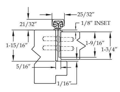
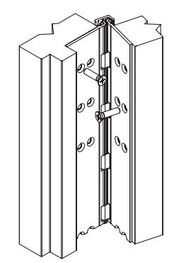
Full Concealed
A111 HD A111 LL
Standard Features
- Full concealed, heavy duty
- ⅛" door inset
- 48" door width maximum
- 450 lbs. door weight maximum
- " LL " model for doors up to 1,000 lbs. (lead-lined staggered hole pattern)
- • Fasteners : 12-24 x ⅞" undercut self-drilling, thread-forming tek machine screws
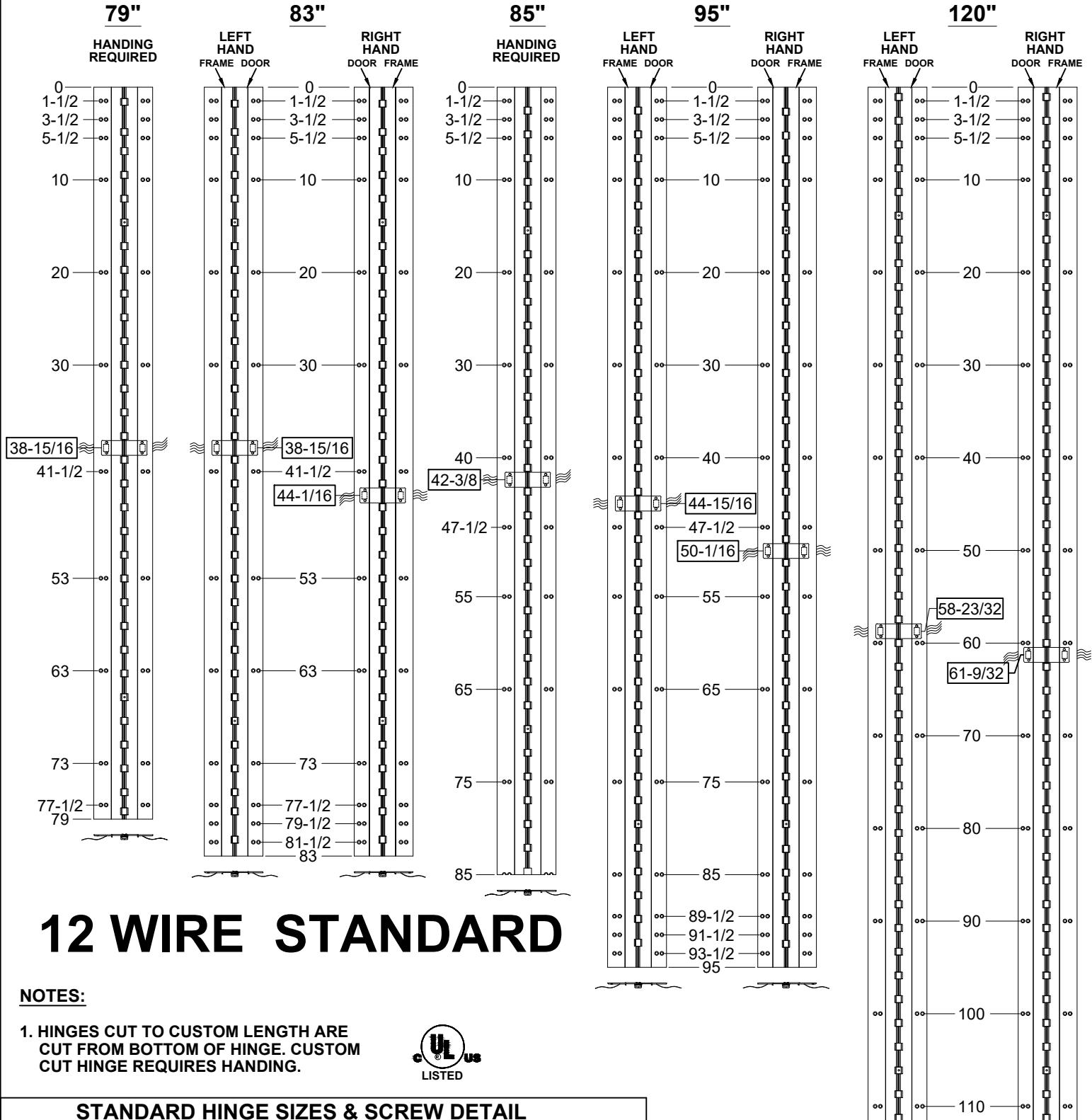
- • Standard lengths : 79", 83", 85", 95" and 120"
- • Finishes : Clear, dark bronze and black anodized
-
• Fire Rating
- Approved for use on metal swinging type minutes (Specify " FR " option for 3 hour rating)
- Approved for use on wood swinging 60 minutes (Specify " FR " option for 90 minute rating)
Options Available
• See pages F-7 to F-8 for option availability and details
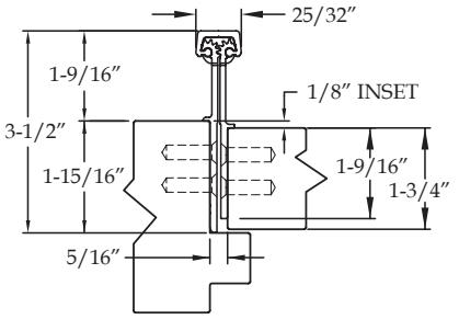
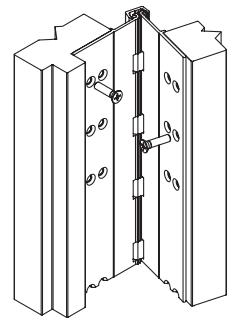
A111 WT
Standard Features
- Full concealed, heavy duty
- ⅛" door inset
- Wide throw for applications that need extra clearance for the door or the frame
- 48" door width maximum
- 450 lbs. door weight maximum
- • Fasteners : 12-24 x ⅞" undercut self-drilling, thread-forming tek machine screws
- • Standard lengths : 79", 83", 85", 95" and 120"
- • Finishes : Clear, dark bronze and black anodized
-
• Fire Rating
- Approved for use on metal swinging type minutes (Specify " FR " option for 3 hour rating)
- Approved for use on wood swinging 60 minutes (Specify " FR " option for 90 minute rating)
Options Available
• availability and details


www.abhmfg.com
E-mail: abhinfo@abhmfg.com Architectural Builders Hardware Mfg., Inc. 1222 Ardmore Ave., Itasca, IL 60143 630.875.9900; FAX 800.9FAXABH (932.9224)
A111WT ALUMINUM GEARED HINGE
© 2018 ABH Mfg., Inc. printed in USA
PAGE 1 OF 1 REVISED 9-10-20
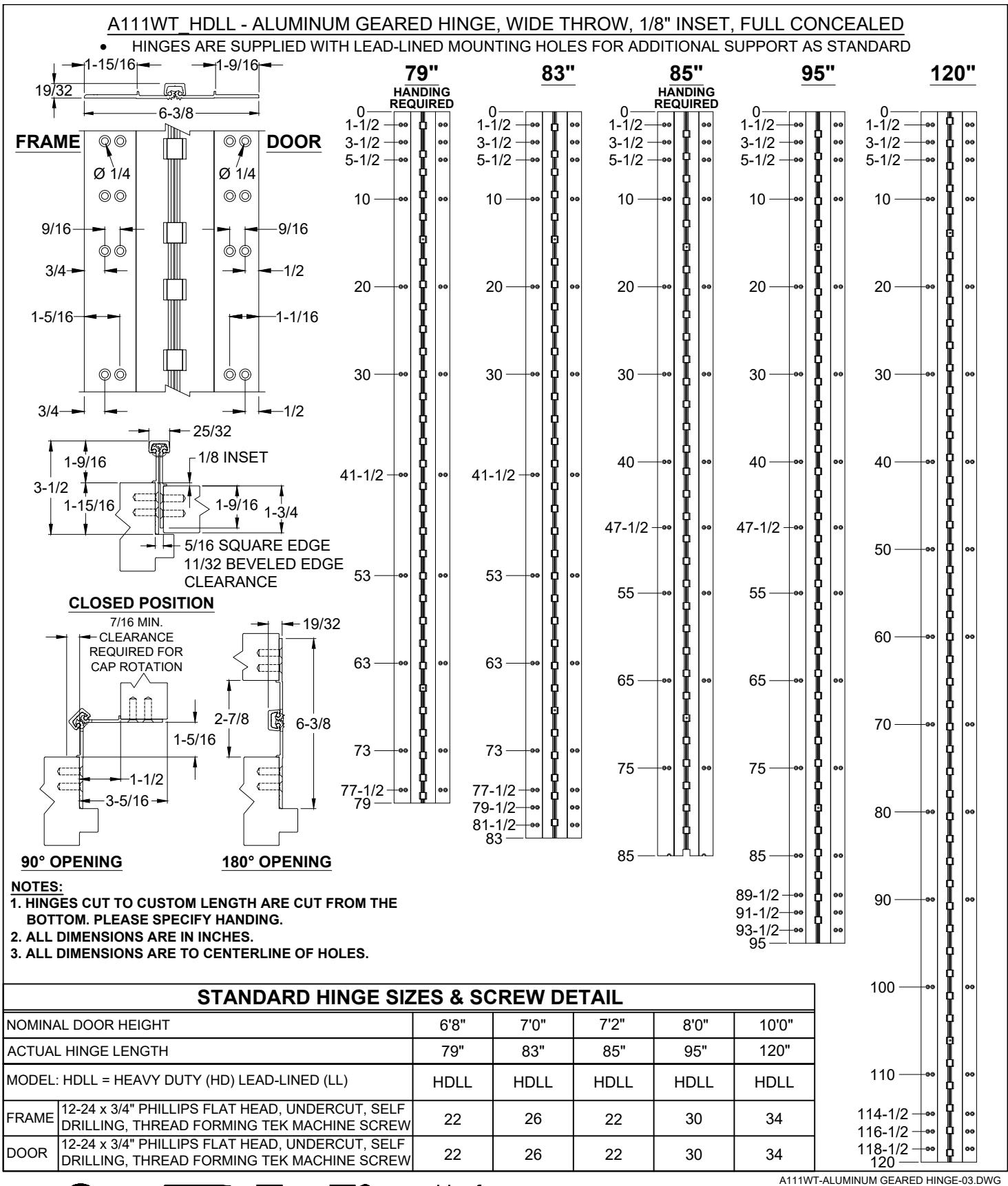
A111WT - EA OPTION, EASY ACCESS CONCEALED ELECTRIFICATION ALUMINUM GEARED HINGE, WIDE THROW, 1/8" INSET, FULL CONCEALED
HINGES ARE SUPPLIED WITH LEAD-LINED MOUNTING HOLES FOR ADDITIONAL SUPPORT AS STANDARD
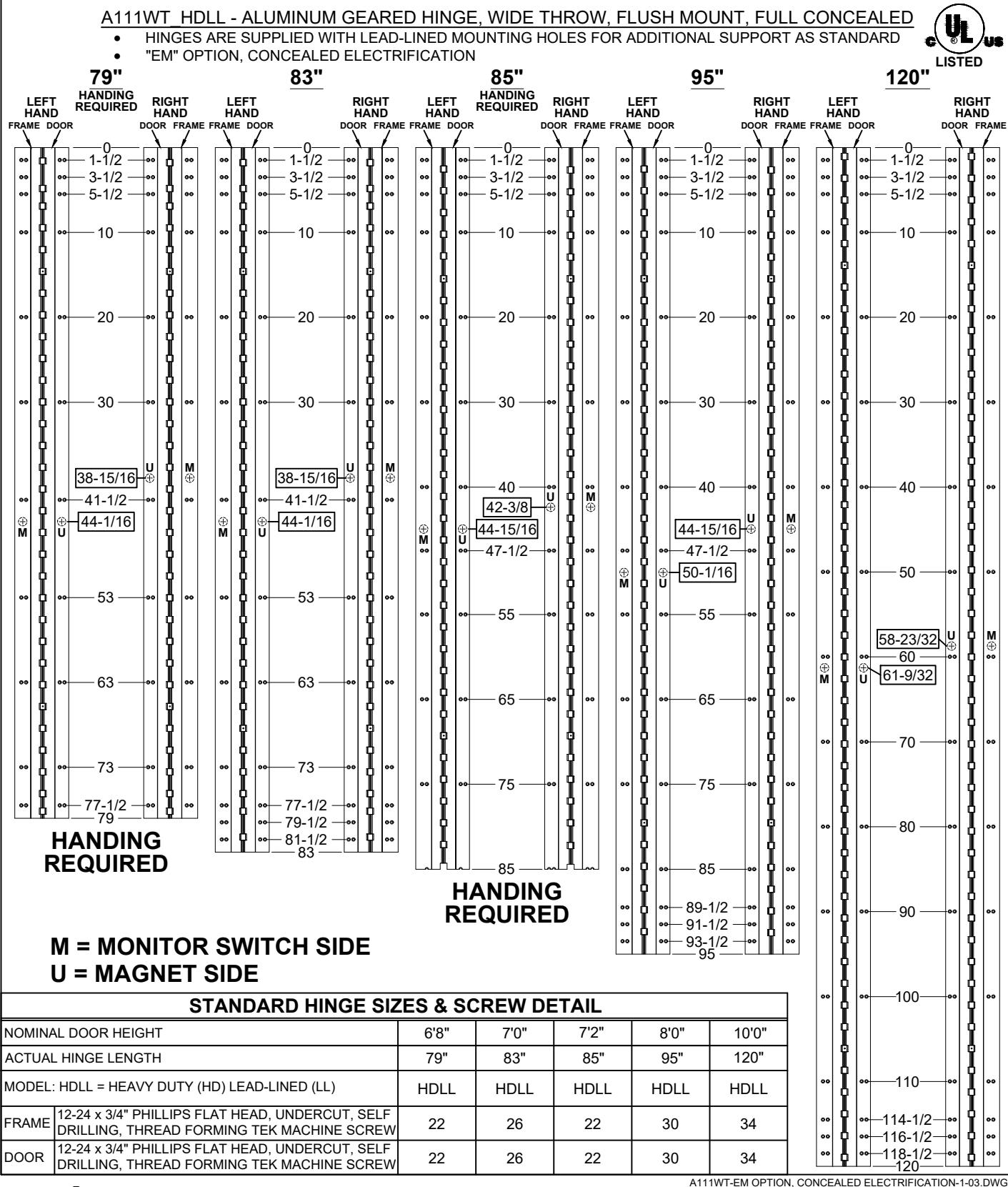
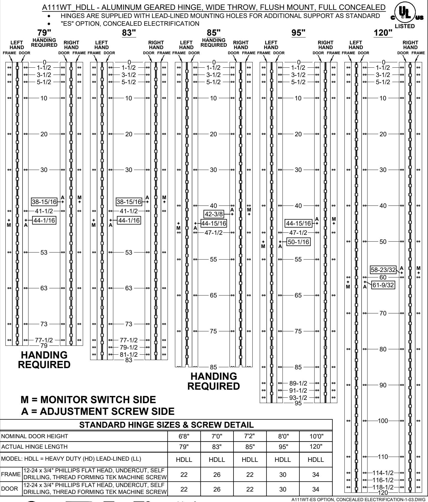
STANDARD HINGE SIZES & SCREW DETAIL 7'0" NOMINAL DOOR HEIGHT 6'8" 7'2" 8'0" 10'0 ACTUAL HINGE LENGTH 120 79' 83' 85' 95' 12-24 x 3/4" PHILLIPS FLAT HEAD, UNDERCUT, SELF FRAME 22 26 22 30 34 DRILLING, THREAD FORMING TEK MACHINE SCREW 12-24 x 3/4" PHILLIPS FLAT HEAD, UNDERCUT, SELF DOOR 22 26 22 30 34 DRILLING, THREAD FORMING TEK MACHINE SCREW
A111WT-EA OPTION, EASY ACCESS CONCEALED ELECTRIFICATION-1-00.DWG
www.abhmfg.com E-mail: abhinfo@abhmfg.com Architectural Builders Hardware Mfg., Inc. 1222 Ardmore Ave., Itasca, IL 60143
A111WT - "EA" OPTION EASY ACCESS CONCEALED ELECTRIFICATION
114-1/2
116-1/2
118-1/2
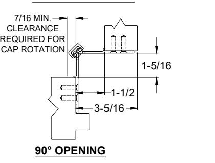
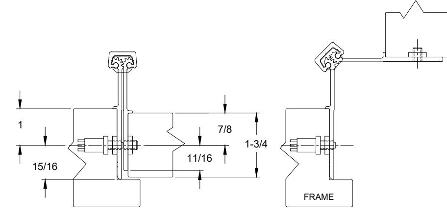
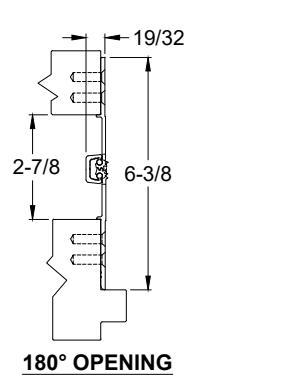
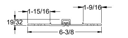
A111WT - EA OPTION, EASY ACCESS CONCEALED ELECTRIFICATION, ALUMINUM GEARED HINGE, WIDE THROW, 1/8" INSET, FULL CONCEALED HINGES ARE SUPPLIED WITH LEAD-LINED MOUNTING HOLES FOR ADDITIONAL SUPPORT AS STANDARD CLEARANCE FRAME LEAF LEAF 550 DRILL 3/4" 6-3/8 THRU-WIRES HOLES FOR FRAME DOOR Ø 1/4 Ø 1/4 9/16 -9/16 12 WIRE ⌽⌽ 3/4-5/8--1/2 #6 SPANNER FLAT HEAD 1-5/16 1-1/16 SECURITY SCREW PROVIDED STANDARD (4 PLACES) LEAF ROTATION WIRE TRANSFER VIEW 12 WIRE 25/32 5/8 1/8 INSET 1-9/16 1-15/16 ፟ 1-9/16 3-1/2 1-1/16 1-5/16 1-15/16 1-9/16 ISOMETRIC VIEW 180° OPENING 5/16 SQUARE EDGE 11/32 BEVELED EDGE WIRE TRANSFER VIEW CLEARANCE ISOMETRIC VIEW ~90° OPENING 7/16 MIN. EZ CONNECT OPTION CLEARANCE REQUIRED FOR CAP ROTATION NOTES: 8642 4)2 ΠN 1. MOLEX ® CONNECTOR OPTION 7531 3 1 AVAILABLE - SUFFIX "EZ". 1-5/16 1 VIOLET * SPECIFY ELECTRIFIED HARDWARE 2 RFD 2. GRAY WHITE MANUFACTURER FOR CONNECTOR GREEN 3, PINK COMPABILITY ORANGE 4, TAN 3-5/16 6, BLUE 7, BROWN 8, YELLOW 90° OPENING SPECIFICATION: 19/32 DESCRIPTION: SINGLE CONDUCTOR #22 AWG MINIATURE HOOK-UP WIRE FOR APPLICATIONS REQUIRING EXTREME FLEXIBILITY. CONDUCTOR: #22 AWG 168/44 (0.002") SOFT BARE COPPER LHL. 2-7/8 6-3/8 INSULATION: PROPRIETARY FORMULATION PVC 0.010" NOM. WALL MEETS VW-1 FLAME REQUIREMENT. DIAMETER: 0.053" ± 0.003". RESISTANCE: 16.7 OHMS MAX. @ 20°C, PER 1000 FT. VOLTAGE RATING: 600 VOLTS RMS, DEPENDING ON SPECIFICATION. 180° OPENING AVAILABLE AS ROHS COMPLIANT.
www.abhmfg.com E-mail: abhinfo@abhmfg.com Architectural Builders Hardware Mfg., Inc. 1222 Ardmore Ave., Itasca, IL 60143
A111WT - "EA" OPTION EASY ACCESS CONCEALED ELECTRIFICATION
A111WT-EA OPTION, EASY ACCESS CONCEALED ELECTRIFICATION-2-00.DWG

www.abhmfg.com E-mail: abhinfo@abhmfg.com Architectural Builders Hardware Mfg., Inc. 1222 Ardmore Ave., Itasca, IL 60143 630.875.9900; FAX 800.9FAXABH (932.9224)
A111WT - "EM" OPTION CONCEALED ELECTRIFICATION
© 2020 ABH Mfg., Inc. printed in USA
PAGE 1 OF 2 REVISED 10-29-20

www.abhmfg.com E-mail: abhinfo@abhmfg.com Architectural Builders Hardware Mfg., Inc. 1222 Ardmore Ave., Itasca, IL 60143 630.875.9900; FAX 800.9FAXABH (932.9224)
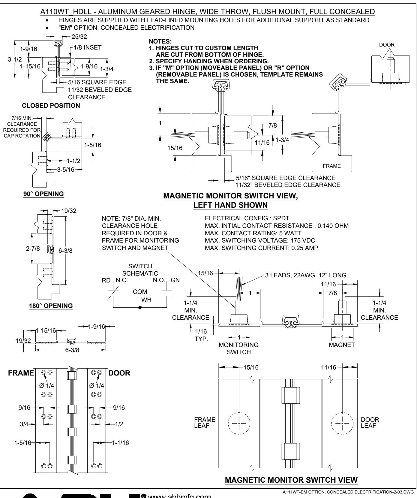
A111WT - "EM" OPTION CONCEALED ELECTRIFICATION
© 2020 ABH Mfg., Inc. printed in USA
PAGE 2 OF 2 REVISED 10-29-20
ABH* MANUFACTURING INC.
www.abhmfg.com E-mail: abhinfo@abhmfg.com Architectural Builders Hardware Mfg., Inc. 1222 Ardmore Ave., Itasca, IL 60143 630.875.9900; FAX 800.9FAXABH (932.9224)
A111WT - "ES" OPTION CONCEALED ELECTRIFICATION
© 2020 ABH Mfg., Inc. printed in USA
PAGE 1 OF 2 REVISED 10-29-20
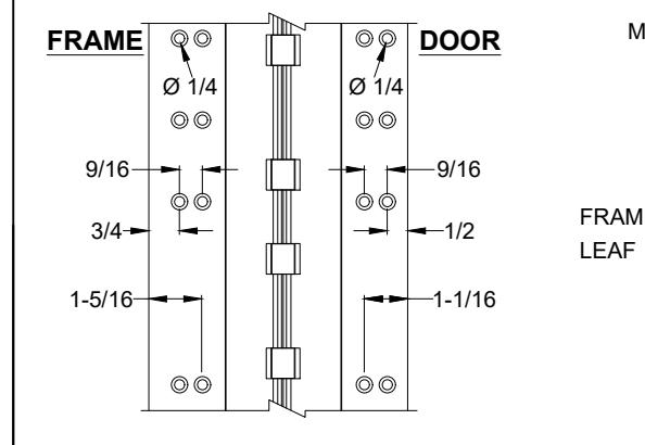
A111WT - "ES" OPTION, CONCEALED ELECTRIFICATION, FULL CONCEALED, ALUMINUM GEARED HINGE
NOTES:
- 1. HINGES CUT TO CUSTOM LENGTH ARE CUT FROM BOTTOM OF HINGE.
- 2. SPECIFY HANDING WHEN ORDERING.
- 3. IF "M" OPTION (MOVEABLE PANEL) OR "R" OPTION (REMOVABLE PANEL) IS CHOSEN, TEMPLATE REMAINS THE SAME.
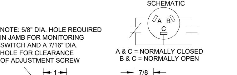
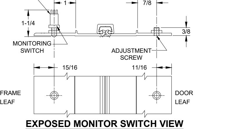
EXPOSED MONITOR SWITCH VIEW, LEFT HAND SHOWN
www.abhmfg.com E-mail: abhinfo@abhmfg.com Architectural Builders Hardware Mfg., Inc. 1222 Ardmore Ave., Itasca, IL60143 630.875.9900; FAX 800.9FAXABH (932.9224)
A111WT-ES OPTION, CONCEALED ELECTRIFICATION-2-03.DWG
SWITCH
A111WT - "ES" OPTION CONCEALED ELECTRIFICATION
c 2020 ABH Mfg., Inc. printed in USA
REVISED 10-29-20 PAGE 2 OF 2
DOOR
Aluminum Continuous Geared Hinges

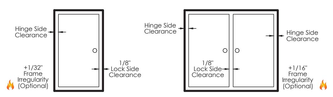
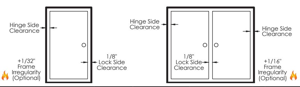
Door Clearance Chart Squared Edge
| Single | e Door | - S | quared | Ed | ged | |||
|---|---|---|---|---|---|---|---|---|
| Hinç | ge Model |
Hinge
Thickness |
+ |
Lock Side
Clearance |
+ |
*Frame //
Irregularity (OPTIONAL) |
= |
Square Edged Door
Undersized (Single) |
|
Full
Concealed |
A110, A110WT, A111
A111WT, A120,A140, A150, A160, A240, A260, A270, A410 |
5/16" | + | 1/8" | + | 1/32" | = | 15/32" |
| A130, A135 | 13/16" | + | 1/8" | + | 1/32" | = | 31/32" | |
|
Half
Surface |
A211, A213, A450, A460,
A520, A530, A540, A550 |
3/16" | + | 1/8" | + | 1/32" | = | 11/32" |
|
Full
Surface |
A210, A570, A571, A575 | 1/16" | + | 1/8" | + | 1/32" | = | 7/32" |
Single Door
Pair of Doors
| Pair o | f Doors | - $ | quared | Ec | dged | |||
|---|---|---|---|---|---|---|---|---|
| Hing | ge Model |
Hinge
Thickness (Pair) |
+ |
Lock Side
Clearance |
+ |
*Frame //
Irregularity (OPTIONAL) |
= |
Square Edged Door
Undersized (Pair) |
|
Full
Concealed |
A110, A110WT, A111
A111WT, A120, A140, A150, A160, A240, A260, A270, A410 |
5/8" | + | 1/8" | + | 1/16" | = | 13/16" |
| A130, A135 | 1-5/8" | + | 1/8" | + | 1/16" | = | 1-13/16" | |
|
Half
Surface |
A211, A213, A450, A460,
A520, A530, A540, A550 |
1/4" | + | 1/8" | + | 1/16" | = | 7/16" |
|
Full
Surface |
A210, A570, A571, A575 | 1/8" | + | 1/8" | + | 1/16" | = | 5/16" |
* 1/16& quot; Frame Irregularity Allowance, Optional and included in all Total Door Undersize for single and pairs of doors

Aluminum Continuous Geared Hinges

Door Clearance Chart Beveled Edge
| Single | e Door | - | Bevelec | l E | dged | |||||
|---|---|---|---|---|---|---|---|---|---|---|
| Hinç | ge Model |
Hinge
Thickness |
+ |
Lock Side
Clearance |
+ |
* Frame ()
Irregularity (OPTIONAL) |
+ |
Beveled
Door Clearance |
= |
Beveled
Edged Door Undersized (Single) |
|
Full
Concealed |
A110, A110WT, A111
A111WT, A120,A140, A150, A160, A240, A260, A270, A410 |
5/16" | + | 1/8" | + | 1/32" | + | 1/32" | = | 1/2" |
| A130, A135 | 13/16" | + | 1/8" | + | 1/32" | + | 1/32" | = | 1" | |
|
Half
Surface |
A211, A213, A450, A460,
A520, A530, A540, A550 |
3/16" | + | 1/8" | + | 1/32" | + | 1/32" | = | 3/8" |
|
Full
Surface |
A210, A570, A571, A575 | 1/16" | + | 1/8" | + | 1/32" | + | N/A | = | 7/32" |
Single Door
Pair of Doors
| Pair o | f Doors | S - | Bevele | d E | dged | |||||
|---|---|---|---|---|---|---|---|---|---|---|
| Hinç | ge Model |
Hinge
Thickness (Pair) |
+ |
Lock Side
Clearance |
+ |
* Frame
Irregularity (OPTIONAL) |
+ |
Beveled
Door Clearance |
= |
Beveled
Edged Door Undersized (Pair) |
|
Full
Concealed |
A110, A110WT, A111
A111WT, A120, A140, A150, A160, A240, A260, A270, A410 |
5/8" | + | 1/8" | + | 1/16" | + | 1/16" | = | 7 8 " |
| A130, A135 | 1-5/8" | + | 1/8" | + | 1/16" | + | 1/16" | = | 1-7/8" | |
|
Half
Surface |
A211, A213, A450, A460,
A520, A530, A540, A550 |
1/4" | + | 1/8" | + | 1/16" | + | N/A | = | 7/16" |
|
Full
Surface |
A210, A570, A571, A575 | 1/8" | + | 1/8" | + | 1/16" | + | N/A | = | 5/16" |
* 1/16& quot; Frame Irregularity Allowance, Optional and included in all Total Door Undersize for single and pairs of doors

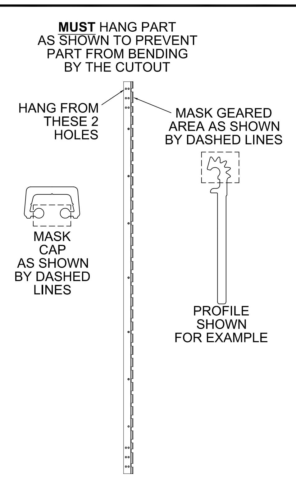
POWDER COAT MASKING

® www.abhmfg.com
E-mail: abhinfo@abhmfg.com Architectural Builders Hardware Mfg., Inc. 1222 Ardmore Ave., Itasca, IL 60143 630.875.9900; FAX 800.9FAXABH (932.9224)
POWDER COAT MASKING-00.DWG
INSTALLATION INSTRUCTIONS FOR FULL CONCEALED HINGES
A110HD/LL, A111HD/LL, A130HD, A135HD, A140HD/LL, A150HD/LL, A160HD/LL A240HD/LL, A260HD/LL, A270HD/LL, A280HD/LL & A410HD/LL
- A. All uncut standard length hinges are non-handed and can be used for right or left hand doors.
- B. Standard length hinges are supplied slightly shorter than nominal door height to accommodate threshold and carpeting clearances.
CUTTING THE HINGE TO FIT
- · Keep hinge in the closed position
- · Determine HANDING if required. Not all hinges will become handed after cutting.
- · Cut one end of the hinge only. Cut end will be installed at the bottom (Six-hole pattern remains at the top)
- · Use a Metal Cutting Saw cut through the gear cap first.
Note: If cut length interferes with a set screw bearing remove it and switch it with a plain bearing above the cut location.
FRAME PREP
With the hinge in the open position
1. Locate the top of the hinge 1/8" below the header
With the frame leaf flange tight against the frame
2. Mark or Center Punch hole locations
Note: If using wood screws drill a 5/32" pilot hol e DO NOT ATTACH HINGE TO FRAME AT THIS TIME
ATTACH THE HINGE TO THE DOOR
- 4. Position Door Leaf on door. Door leaf alignment flange or door leaf lip must be seated against door edge.
- 5. Align the top end of the hinge to be absolutely flush with the top of the door.
- 6. Mark or Center Punch hole locations
- 7. Using the provided Self Drilling/Thread Forming Screws and the proper drive bit please proceed to attach the hinge to the door Note: If using wood screws drill a 5/32" pilot hol e.
ATTACHING DOOR TO FRAME
- 8. Position door 90 degrees to frame
- 9. Shim door to the proper height to line up the screw holes in hinge frame leaf with the marks at the top of the frame.
- 10. Install two screws at the top of the hinge to hold in place
- 11. Remove shim and align the remaining holes. Install two additional screws in the middle and at the bottom.
- 12. Check door for proper swing and clearance before installing remaining screws, making necessary adjustments.
- 13. Install the remaining fasteners after any adjustments are made.
REINFORCING AND RIVNUTS
- · No reinforcing is necessary except on extremely high-frequency, extremely heavy or extra-wide doors.
- · Rivnuts are recommended for use in the frame when the door exceeds 450lbs.
Note:RIVNUTS are not to be used with Fire Rated Hinges
PAIRS OF DOORS WITH MULLIONS
- · If the mullion is between the doors, install as single doors.
- · If the mullion is behind the doors, install as a double doors.
GROUT/SLUSHED-IN FRAMES
It is recommended that a mudguard be installed behind the frame for ease of installation. Do not use self-drill screws with grouted steel frames without a mudguard. If no mudguard has been used, drill holes through frame and remove grout for screw clearances. Do not oversize hole.
| SCREW DETAIL | ||||||
|---|---|---|---|---|---|---|
| FRAME |
12-24 x 3/4" PHILLIPS FLAT HEAD, UNDERCUT, SELF
DRILLING, THREAD FORMING TEK MACHINE SCREW |
|||||
| DOOR |
12-24 x 3/4" PHILLIPS FLAT HEAD, UNDERCUT, SELF
DRILLING, THREAD FORMING TEK MACHINE SCREW |
|||||
Note: #12 x 1-1/2" FLAT HEAD UNDERCUT WOOD SCREWS AVAILABLE UPON REQUEST
The following actions will void any warranty, expressed or implied.
- · Failure to Install the hinge according to ABH's specifications and requirements
- · Use of Fasteners other than those supplied with the hinge.
- · Unauthorized field modifications including removing any of the bearings, altering the original finish or painting the hinge.


ABH Manufacturing Inc.
1222 Ardmore Avenue Itasca, IL 60143
Ph: (630)875-9900 Fax: (800) 932-9224
www.abhmfg.com
ANSI/BHMA A156.26-2017 Certified Continuous Hinges
Edge Mounted-Barrel Type-Stainless Steel-Grade 1
ABH Model Number(s): A500, A505, A515
Edge Mounted-Gear Type-Aluminum-Grade 1
ABH Model Number(s): A110(HD/LL), A110WT(HD/LL), A111(HD/LL), A111WT(HD/LL), A130HD, A140(HD/LL), A150(HD/LL), A160(HD/LL), A240(HD/LL), A260(HD/LL), A270(HD/LL), A410(HD/LL)
Full Surface Mounted-Barrel Type-Stainless Steel-Grade 1
ABH Model Number(s): A502, A512
Full Surface Mounted- Gear Type- Aluminum-Grade 1
ABH Model Number(s): A210HD, A570HD, A571HD
Half-Surface Mounted-Barrel Type-Stainless Steel-Grade 1
ABH Model Number(s): A503
Half-Surface Mounted- Gear Type- Aluminum-Grade 1
ABH Model Number(s): A211HD, A213HD, A450HD, A460HD, A530HD, A540HD, A550HD
Half Mortise Mounted-Barrel Type-Stainless Steel-Grade 1
ABH Model Number(s): A504, A506
Half Mortise Mounted- Gear Type- Aluminum-Grade 1
ABH Model Number(s): A520HD
Swing Clear Edge Mounted-Barrel Type-Stainless Steel-Grade 1
ABH Model Number(s): A510, A511, A526, A529
Swing Clear Edge Mounted- Gear Type- Aluminum-Grade 1
ABH Model Number(s): A410(HD/LL), A211HD
HD-denotes Heavy Duty Hinge
LL-denotes Heavy Duty hinge with extra screw holes to accommodate the lead in lead lined doors