abh_A110_HD&LL_techmemo
Open the original PDF document
View PDFAluminum Continuous Geared Hinges

Door Clearance Chart Squared Edge
| Single Door - Squared Edged | ||||||||||
|---|---|---|---|---|---|---|---|---|---|---|
| Hinge Model |
Hinge
Thickness |
+ |
*Frame //
Irregularity (OPTIONAL) |
= |
Square Edged Door
Undersized (Single) |
|||||
|
Full
Concealed |
A110, A110WT, A111
A111WT, A120,A140, A150, A160, A240, A260, A270, A410 |
5/16" | + | 1/8" | + | 1/32" | = | 15/32" | ||
| A130, A135 | 13/16" | + | 1/8" | + | 1/32" | = | 31/32" | |||
|
Half
Surface |
A211, A213, A450, A460,
A520, A530, A540, A550 |
3/16" | + | 1/8" | + | 1/32" | = | 11/32" | ||
|
Full
Surface |
A210, A570, A571, A575 | 1/16" | + | 1/8" | + | 1/32" | = | 7/32" | ||
Single Door
Pair of Doors
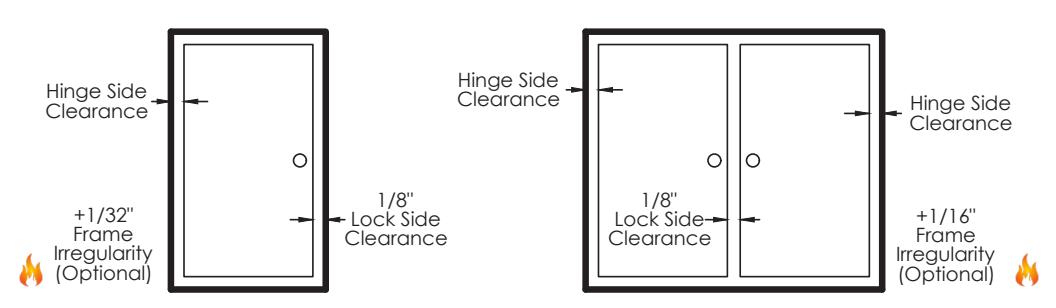
| Pair of Doors - Squared Edged | ||||||||||
|---|---|---|---|---|---|---|---|---|---|---|
| Hinge Model |
Hinge
Thickness (Pair) |
+ |
Lock Side
Clearance |
+ |
*Frame //
Irregularity (OPTIONAL) |
= |
Square Edged Door
Undersized (Pair) |
|||
|
Full
Concealed |
A110, A110WT, A111
A111WT, A120, A140, A150, A160, A240, A260, A270, A410 |
5/8" | + | 1/8" | + | 1/16" | = | 13/16" | ||
| A130, A135 | 1-5/8" | + | 1/8" | + | 1/16" | = | 1-13/16" | |||
|
Half
Surface |
A211, A213, A450, A460,
A520, A530, A540, A550 |
1/4" | + | 1/8" | + | 1/16" | = | 7 /16" | ||
|
Full
Surface |
A210, A570, A571, A575 | 1/8" | + | 1/8" | + | 1/16" | = | 5/16" | ||
* 1/16& quot; Frame Irregularity Allowance, Optional and included in all Total Door Undersize for single and pairs of doors

Aluminum Continuous Geared Hinges

Door Clearance Chart Beveled Edge
| Single Door - Beveled Edged | ||||||||||
|---|---|---|---|---|---|---|---|---|---|---|
| Hinge Model |
Hinge
Thickness |
+ |
Lock Side
Clearance |
+ |
* Frame ()
Irregularity (OPTIONAL) |
+ |
Beveled
Door Clearance |
= |
Beveled
Edged Door Undersized (Single) |
|
|
Full
Concealed |
A110, A110WT, A111
A111WT, A120,A140, A150, A160, A240, A260, A270, A410 |
5/16" | + | 1/8" | + | 1/32" | + | 1/32" | = | 1/2" |
| A130, A135 | 13/16" | + | 1/8" | + | 1/32" | + | 1/32" | = | 1" | |
|
Half
Surface |
A211, A213, A450, A460,
A520, A530, A540, A550 |
3/16" | + | 1/8" | + | 1/32" | + | 1/32" | = | 3/8" |
|
Full
Surface |
A210, A570, A571, A575 | 1/16" | + | 1/8" | + | 1/32" | + | N/A | = | 7/32" |
Single Door
Pair of Doors
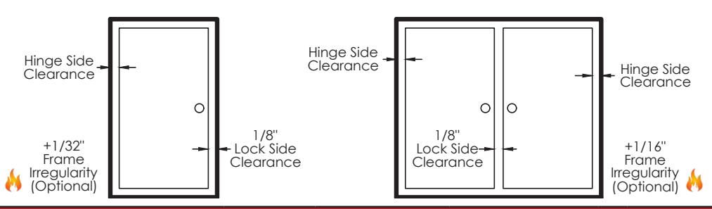
| Pair of Doors - Beveled Edged | ||||||||||
|---|---|---|---|---|---|---|---|---|---|---|
| Hinge Model |
Hinge
Thickness (Pair) |
+ |
Lock Side
Clearance |
+ |
* Frame ()
Irregularity (OPTIONAL) |
+ |
Beveled
Door Clearance |
= |
Beveled
Edged Door Undersized (Pair) |
|
|
Full
Concealed |
A110, A110WT, A111
A111WT, A120, A140, A150, A160, A240, A260, A270, A410 |
5/8" | + | 1/8" | + | 1/16" | + | 1/16" | = | 7 8 " |
| A130, A135 | 1-5/8" | + | 1/8" | + | 1/16" | + | 1/16" | = | 1-%" | |
|
Half
Surface |
A211, A213, A450, A460,
A520, A530, A540, A550 |
1/4" | + | 1/8" | + | 1/16" | + | N/A | = | 7/16" |
|
Full
Surface |
A210, A570, A571, A575 | 1/8" | + | 1/8" | + | 1/16" | + | N/A | = | 5/16" |
* 1/16& quot; Frame Irregularity Allowance, Optional and included in all Total Door Undersize for single and pairs of doors

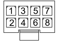
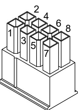
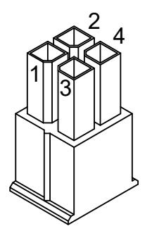
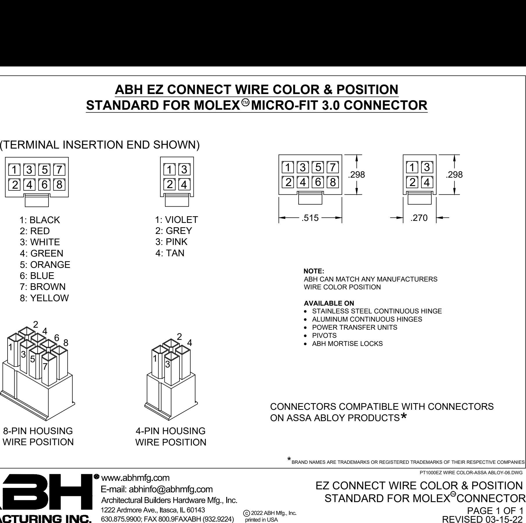

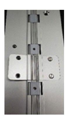
EA THRU-WIRE REPLACEMENT INSTRUCTIONS
Removal of Old Wires
- 1. Turn off Power to avoid shock.
- 2. Remove (4) #6 Spanner Flat Head Screws from the covers on the face of each hinge leaf.
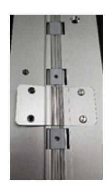
3. Remove (2) covers to expose the wires.
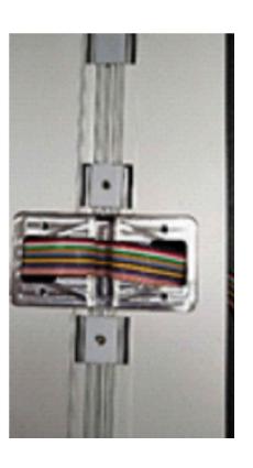
4. Pull wires through opening and disconnect from power source and electrified hardware.

EA THRU-WIRE REPLACEMENT.DWG
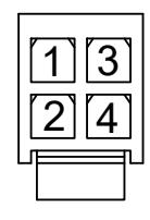
EA THRU-WIRE REPLACEMENT INSTRUCTIONS
Installation of New Wire Ribbon
All wire connections must follow local codes and/or ABH Manufacturing's Minimum Requirements** to ensure proper and lasting connections
**ABH requires the use of wire nuts and electrical tape or Crimp Connectors when connecting wires to their source or supplied EZ Connectors
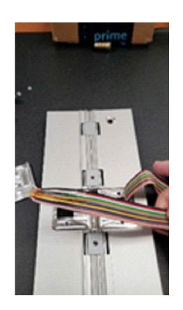
- 1. Connect wire to the power source (FRAME SIDE) and pass wires back through hinge and frame opening.
- 2. Connect wires on DOOR side to electrified hardware and pass wires back through the hinge and door opening.
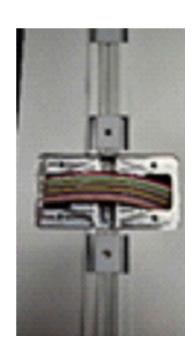
- 3. Excess Wire Ribbon should then be folded into the void of the cap.
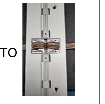
4. Once wires are properly connected, line up the Thru-Wire Face plate gears and fasten with (4) #6 Spanner Flat Head Screws, making sure the plates sit flush to the face of the hinge leafs.
5. Turn Power back on

www.abhmfg.com E-mail: abhinfo@abhmfg.com Architectural Builders Hardware Mfg., Inc. 1222 Ardmore Ave., Itasca, IL 60143 630.875.9900; FAX 800.9FAXABH (932.9224)
EA THRU-WIRE REPLACEMENT.DWG