Zero Automatic Door Bottoms Models 320 350 351 352 360 361 362 364 365 366 367 368 & 369 Installation Instructions 112445
Open the original PDF document
View PDF

47255399
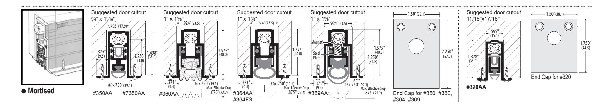
Models 320, 350, 7350, 351, 352, 360, 361, 362, 364, 365, 366, 367, 368, & 369 Automatic Door Bottoms
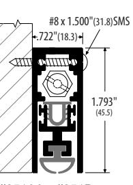
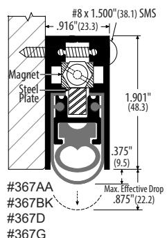
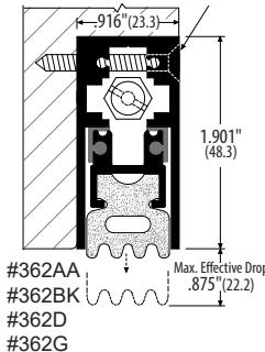
#8 x 1.500"(38.1) SMS

Installation Instructions

#351AA #351D #351BK #351G
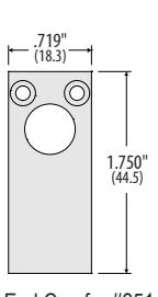
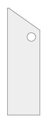
End Cap for #351
#365AA .875"(22.2) #365BK #365D #365FS #365G
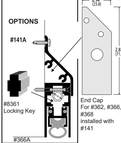
- 1.00"(24.5) -1.750 End Cap for #361, #365. #367
-1.00"(24.5)-
End Cap for #362.
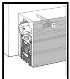
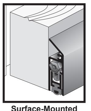
Surface-Mounted Automatic Door
Note: #8361 Locking Key can't be used with end caps.
Bottom With Watershed Option
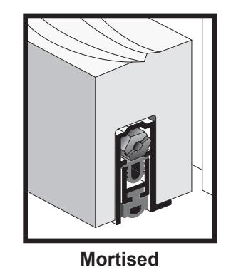
Semi-Mortised
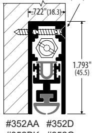
#8x1.500"(38.1) SMS
#352BK #352G
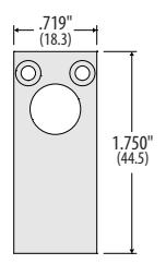
End Cap for #352
.875"(22.2)
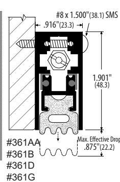
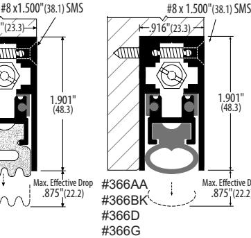
#8 x 1.500"(38.1) SMS
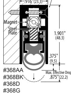
# 366, #368

Positive Pressure Tested Gasketing Materials For Fire Doors. For application to hollow metal type fire doors rated up to 3 hours, fiberglass or wood composite type fire doors rated up to 1-1/2 hours and wood type fire doors rated up to 20 minutes. Category J
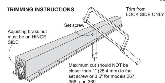
- 1. Cut the automatic door bottom (ADB) to the size needed. Leave 1/16" (1.6 mm) clearance on each end
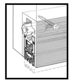
- 2. Place the ADB on the door. All surface and semi-mortised units must be mounted on the push side of the door (side where the door stop is).
- 3. Fasten with screws provided. The adjusting brass nut must be on the hinge side and should not be adjusted until the unit has been mounted.
- 4. Optimum clearance between door bottom unit and floor or sill is 3/8" (9.5 mm). For model #369 clearance is 5/8" (15.9 mm).
- 5. Final adjustment to control the drop of the automatic door bottom can be made once the unit is installed, by turning the adjusting brass nut in or out. Open and close the door while adjusting the brass nut to get the desired seal with the floor or sill. Do not over adjust.
Customer Service


© Allegion 2019
Models 321, 323 Automatic Door Bottoms - Handed

#8 x 1.50"(38.1)
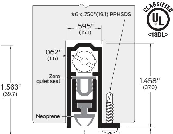
.062
(1.6)
Zero
quiet seal
#321AA
(L.H. shown)
Handed
TPHSMS
.595"_
ø.4375"
.598"
(15.2)
End Caps for #321
(39.7)
Handed
(L.H. shown)
1.969"
(50.0)
2.00"
(50.8)
Max. drop
.750"(19.1)
Max. drop
.750"(19.1)
TO INSTALL:
- Surface mounted unit must be mounted on the push side of the door stop (side where the door stop is).
- The brass adjusting nut must be on the hinge side and should not be adjusted until the unit has been mounted.
- Leave 1/16" (1.6) clearance on each end.
- Optimum clearance between door bottom unit and floor or sill is 3/8" (9.5).
Positive Pressure Tested Gasketing Materials For Fire Doors. For application to hollow metal type fire doors rated up to 3 hours, fiberglass or wood composite type fire doors rated up to 1-1/2 hours and wood type fire doors rated up to 20 minutes. Category J
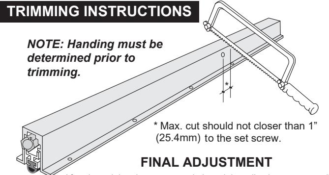
After the unit has been mounted, thread the adjusting nut out until the seal contacts the floor/sill when the door is closed. Take care not to thread the adjusting too far out as that can damage the door bottom.
| Additional Notes: | |
|---|---|
| 1. None | |
| Revision History | Revision Description: | ||||||||
|---|---|---|---|---|---|---|---|---|---|
| А | В | С | D | Е | F | D > Revised artwork | |||
| xxxxx | 062679 | ||||||||
| Material White Paper | Edited By | Approved By | EC Number | Release Date | |||||
| J. Ellis | M. Roberts | 062679 | 03-27-19 | ||||||
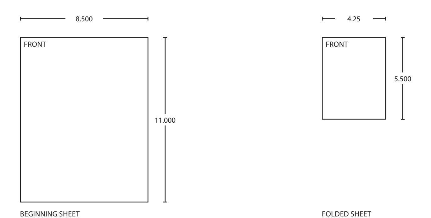
| Notes 1. printed two sides 2. printed black 3. tolerance ± .13 4. printed in country may vary | Title Zero automatic door bottoms installation instruction | ||||||||
| Creation Date xx-xx-xx | Number 47255399 |
Revision
D |
|||||||
| 5. drawings not to scale |
Created By
X. XXXXX |
Activity
3899 Hancock Expwy |
|||||||
| Software: InDesign CS6 | Security, CO 80911 | Allegion 2019 | |||||||