ZKTeco USA ProCapture-T ProRF-T Installation Guide
Open the original PDF document
View PDF

Quick Start Guide

ProCapture-T & ProRF-T + ZKBioSecurity 3.0
CONTENT
| Safety Precautions | 2 |
|---|---|
| Device Overview | 3 |
| Product Dimensions & Installation | 5 |
| Power Connection | 6 |
| Ethernet Connection | 7 |
| RS485 Connection | 8 |
| Lock Relay Connection | 9 |
| Wiegand Output Connection | |
| Standalone Installation | 12 |
| Device Operation | 13 |

ZKBioSecurity Software Installation and Setup starts at Page 16
Safety Precautions
The following precautions are to keep users safe and prevent any damage. Please read carefully before installation.


Do not install the device in a place subject to direct sunlight, humidity, dust or soot.

Do not place a magnet near the product. Magnetic objects such as magnets, CRTs, TVs, monitors or speakers may damage the device.

Do not place the device next to heating equipment.

Be careful not to let liquid like water, drinks or chemicals leak inside the device.

Do not let children touch the device without supervision.

Do not drop or damage the device.

Do not disassemble, repair or alter the device.

Do not use the device for any other purpose than specified.

Clean the device often to remove dust on it. In cleaning, do not splash water on the device but clean it with a smooth cloth or towel.
Contact your supplier in case of a problem.
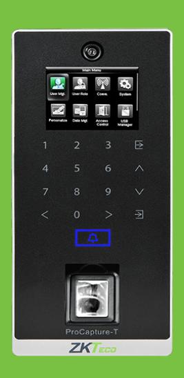
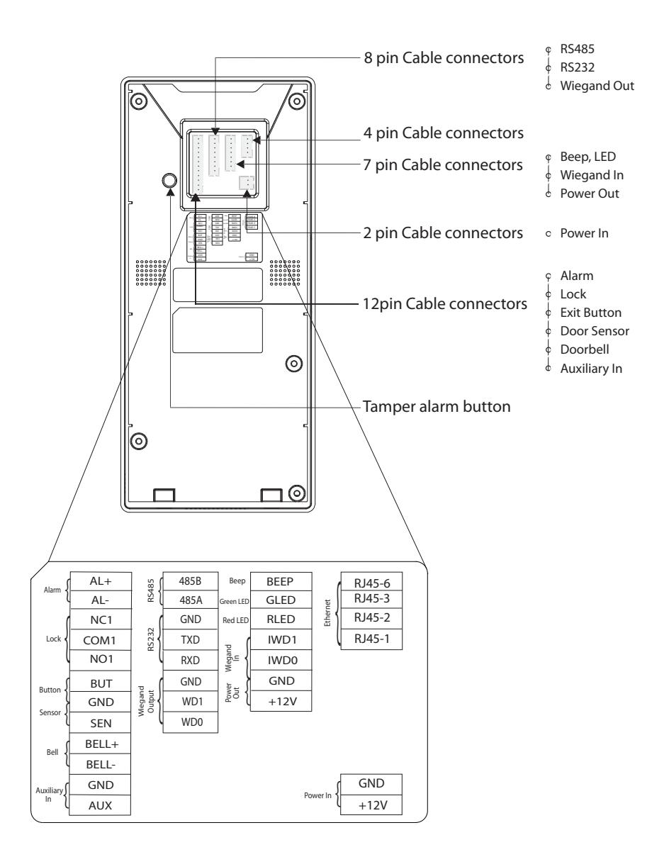
Device Overview
Not all products have fingerprint or card function.
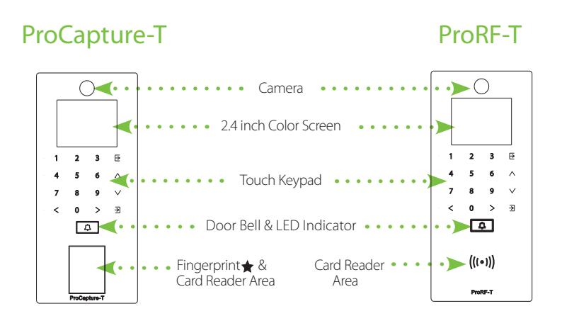
Left side & bottom view is common for both the devices
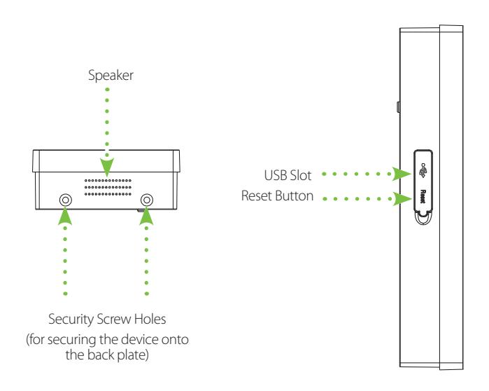
Device Overview
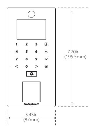
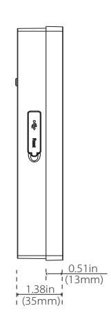
Product Dimensions & Installation
Product Dimensions
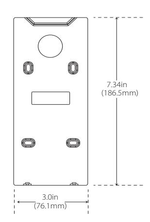
Mounting the Device on the Wall
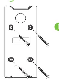
Fix the back plate onto the wall using wall mounting screws.
Note: We recommend drilling the mounting plate screws into solid wood (i.e. stud/beam). If a stud/beam cannot be found, use supplied drywall plastic anchors.
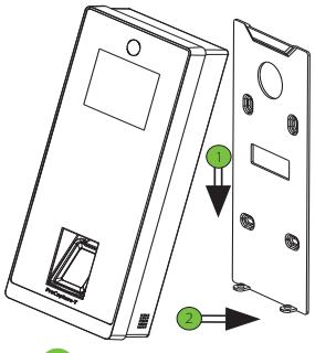
2 Insert the device to back plate.
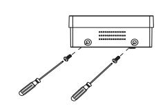
3 Use security screws to fasten the device to back plate.
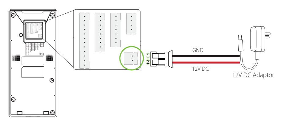
Power Connection
Without UPS
With UPS (Optional)
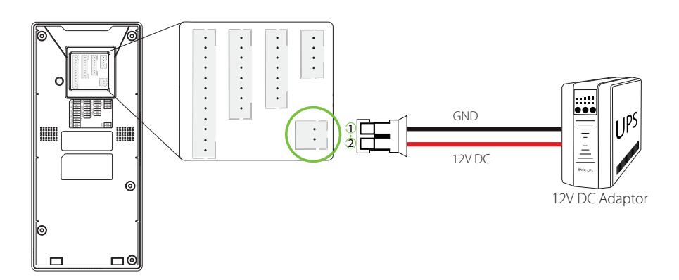
Recommended Power Supply
- 12V±10%, at least 500mA
- To share the power with other devices, use a power supply with higher current ratings.
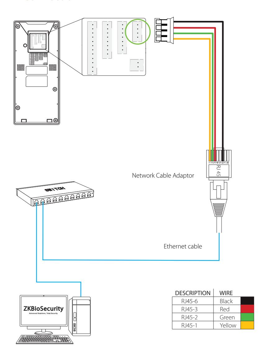
Ethernet Connection
LAN Connection
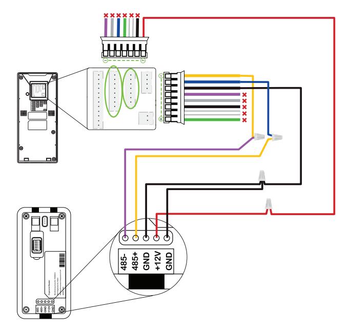
RS485 Connection
RS485 Fingerprint Reader Connection
| DESCRIPTION | WIRE | PIN | DESCRIP* | TION | WIRE | |||
|---|---|---|---|---|---|---|---|---|
| BEEP X | Purple | 1 | 485B | Yellow | ||||
| GLED 🗶 | Gray | 2 | 485A | Blue | ||||
| RLED X | Blue | 3 | GND | Black | ||||
| IWD1 🗶 | Green | ≭ Do not use | 4 | TXD | × | Purple | ||
| IWD0 × | White | A DO HOL use | 5 | RXD | × | Gray | ||
| GND 🗶 | Black | 6 | GND | × | Black | |||
| +12V | Red | 7 | WD1 | × | White | |||
| 8 | WD0 | × | Green |
Dip Settings
- 1. There are six DIP switches on the back of RS485 fingerprint reader, switches 1-4 are for RS485 address, switch 5 is reserved, switch 6 is for reducing noise on long RS485 cable.
- 2. If RS485 fingerprint reader is powered from the terminal, the length of wire should be less than 100 meters or 330 ft.
- 3. If the cable length is more than 200 meters or 600 ft, the number 6 switch should be ON as below.

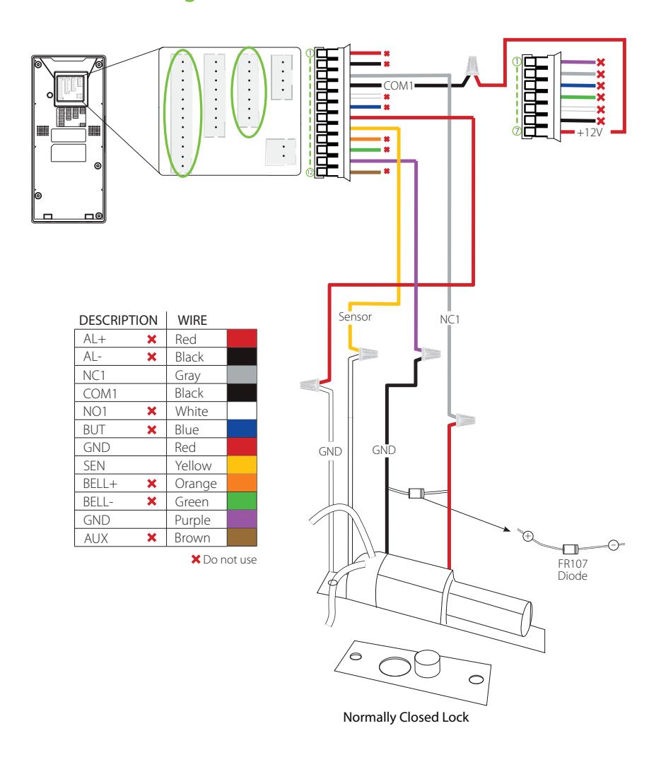
Lock Relay Connection
Device Not Sharing Power with the Lock
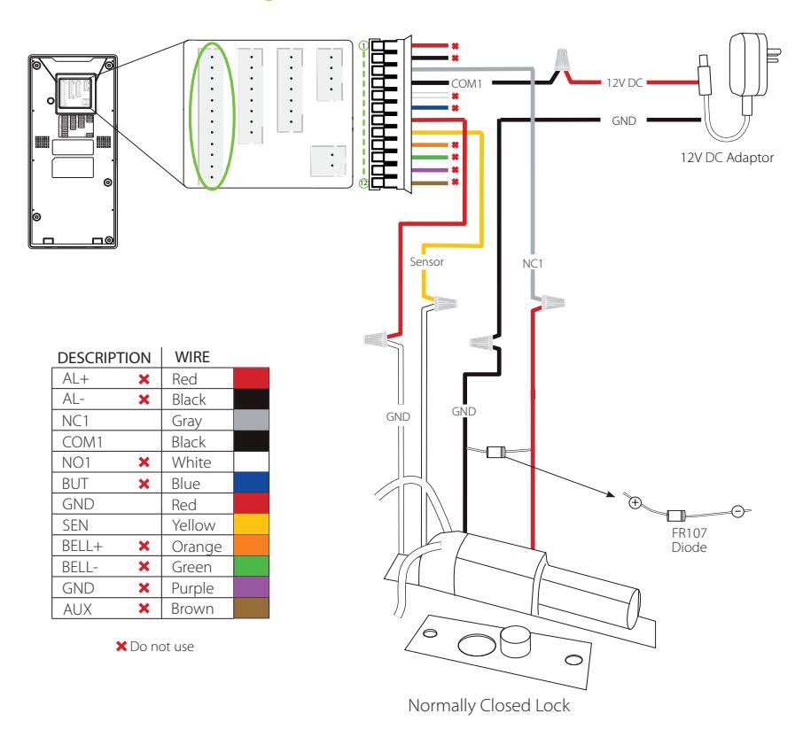
Notes:
- 1. The system supports NO LOCK and NC LOCK. For example the NO LOCK (normally opened at power on) is connected with 'NO1' and 'COM1' terminals, and the NC LOCK (normally closed at power on) is connected with 'NC1' and 'COM1' terminals.
- 2. When electrical lock is connected to the Access Control System, you must parallel one FR107 diode (equipped in the package) to prevent the self-inductance EMF from affecting the system.

Lock Relay Connection
Device Sharing Power with the Lock
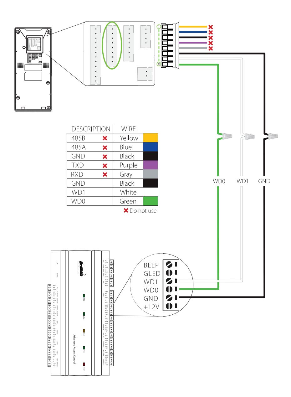
Wiegand Output Connection
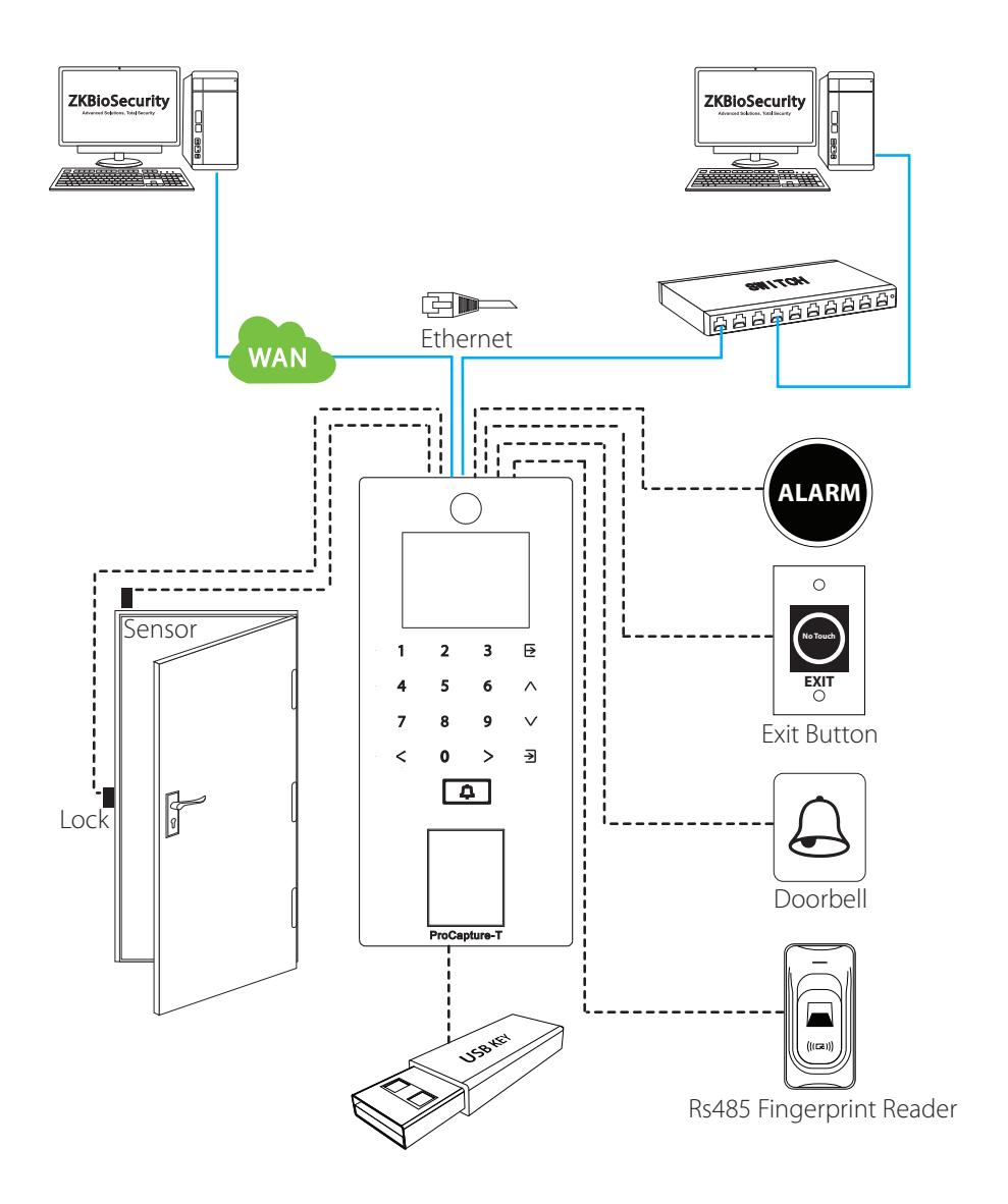
Standalone Installation
Device Operation
Date/Time Settings
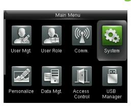
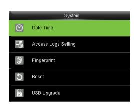
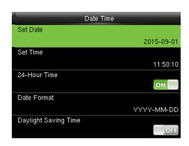
Press icon to enter the Main Menu > System > Date Time to set date and time.
Adding User
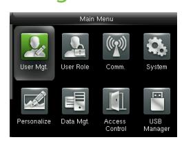
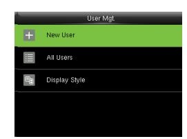
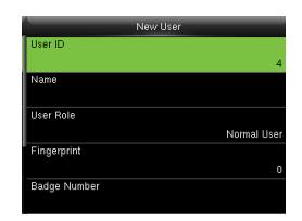
Press icon to enter the Main Menu > User Mgt. > New User to enter the New User adding interface. Settings include entering user ID, user name, choosing user role (Super Admin / Normal User), registering fingerprint / badge number / password, taking user photo , and setting access control role.
Ethernet Settings
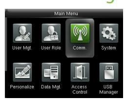
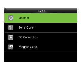
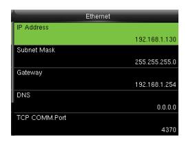
Press icon to enter the Main Menu > Comm. > Ethernet.
The parameters below are the system default values. Please adjust them according to the actual network.
IP Address: 192.168.1.201 Subnet Mask: 255.255.255.0
Gateway: 0.0.0.0
DNS: 0.0.0.0
TCP COMM. Port: 4370
DHCP: Dynamic Host Configuration Protocol, which dynamically allocate IP addresses for clients via server. If DHCP is enabled, IP cannot be set manually.
Display in Status Bar: To set whether to display the network icon on the status bar of initial interface.
Not all products have this function, the real product shall prevail.
Device Operation
ADMS Settings
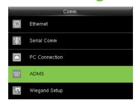
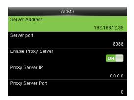

Press icon to enter the Main Menu > Comm. > ADMS, to set the parameters which are used for connecting with the ADMS server.
When the Webserver is connected successfully, the initial interface will display the logo. Server Address: Enter IP address of the ADMS server (namely, the IP address of server where the software is installed).
Server Port: Enter the port number used by the ADMS server.
Enable Proxy Server: Method of enabling proxy. To enable proxy, please set the IP address and port number of the proxy server. Entering proxy IP and server address will be the same.
Note: To connect the device to ZKBioSecurity software, Ethernet and ADMS options must be set correctly.
Access Control Settings
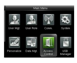
Press icon to enter the Main Menu, press and to select Access Control.
To gain access, the registered user must meet the following conditions:
- 1. User's access time must fall within either user's personal time zone or group time zone.
- 2. User's group must be in the access combo (when there are other groups in the same access combo, verification of members of those groups are also required to unlock the door).
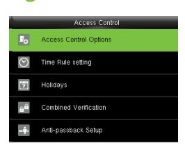
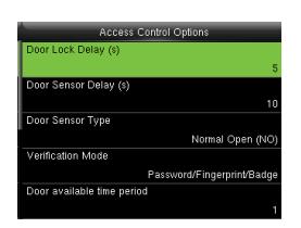
Access Control Options: To set parameters of the lock and other related devices.
Time Rule Setting: To set a maximum of 50 time rules. Each time rule consists of 10 spaces (7 spaces for one week and 3 holiday spaces), each space consists of 3 time periods.
Holidays: To set dates of holiday and the access control time zone for that holiday.
Combined Verification: To set access control combinations. A combination consists of a maximum of 5 access control groups.
Anti-Passback Setup: To prevent passing back which causes risks to security. Once this function is enabled, entry and exit records must be matched in order to open door. In Anti-Passback, Out Anti-Passback and In/Out Anti-Passback functions are available.
Device Operation
Access Control Combination Settings
E.g. : Add an access control combination which requires 2 person's verification from both Access Control Group 1 (set in User Management) and Access Control Group 2.
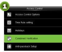
1. In "Access Control" interface, press to select "Combined Verification"; then press to enter the "Combined Verification" list. Click the desired combination and press to enter the modification interface (as shown in figure 2).
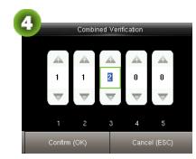
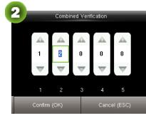
2. Click or to change the number, click or to switch editing box, set the user group number, and click to save and return to "Combined Verification" list (as shown in figure 3).
Note:
- A. A single access control combination can consist of a maximum of 5 access control groups (in order to open door, verification of all 5 users is required).
- B. If the combination is set as shown in figure 3, a user from access control group 2 must obtain verification of 2 users from access control group 1 in order to open door.
- C. Set all access control group number to zero to reset access control combination.
Troubleshooting
-
1.
Fingerprint cannot be read or it takes too long ?
- @ Check whether a finger or fingerprint sensor is stained with sweat, water or dust.
- @ Retry after wiping off finger and fingerprint sensor with dry paper tissue or a mildly wet cloth.
- @ If a fingerprint is too dry, blow on the finger and retry.
-
2.
"Invalid time zone" is displayed after verification?
- @ Contact Administrator to check if the user has the privilege to gain access within that time zone.
-
3.
Verification succeeds but the user cannot gain access?
- @ Check whether the user privilege is set correctly.
- @ Check whether the lock wiring is correct.
- @ Check whether anti-passback mode is in use. In anti-passback mode, only the person who has entered through that door can exit.
-
4.
The Tamper Alarm rings?
- @ To cancel the triggered alarm mode, carefully check whether the device and back plate are securely connected to each other, and reinstall the device properly if necessary.
-
5.
How to cancel alarms?
- @ Verify a registered user.
ZKBioSecurity 3.0
It is recommended to install software version 3.0.3.0 or above

Installation & Setup
| Downloading17 | |
|---|---|
| Installation18 | |
| Adding Device20 | |
| Creating a Time Zone22 | |
| Creating an Access Level23 | |
| Enrolling Personnel24 | |
| Wiegand Format26 | |
| Add & Delete Personnel to Access Level | 27 |
| Real -Time Monitoring28 | |
| Exporting Reports29 |
Downloading
- 1. Go to www.zkaccess.com.
- 2. Download the latest software and related files as required.
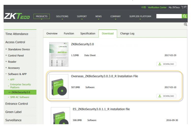
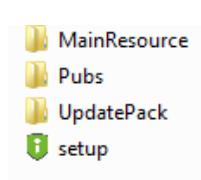
- 3. Once downloaded, extract the .rar file to a new folder.
- 4. Click on setup to begin installation.
Installation
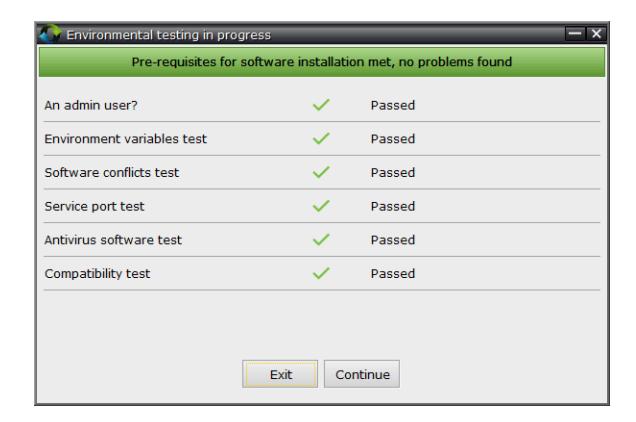
1. System will check the requirements to install the software. Click Continue if all tests are passed, else check the issues and re-test.
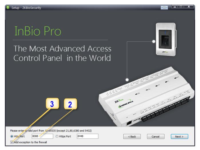
- 2. Add an open port (Default 8088) or ask a network administrator for an open port. Note: Standalone device doesn't support https.
- 3. Click the check box to add firewall exception for this port.
Installation
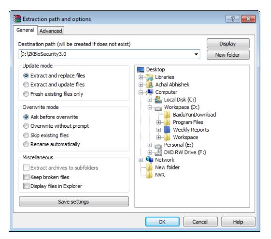
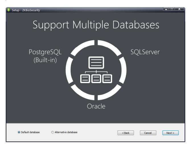
4. Select the mode of database. The default will be PostgreSQL, if you want to select any other database, then select Alternative database.
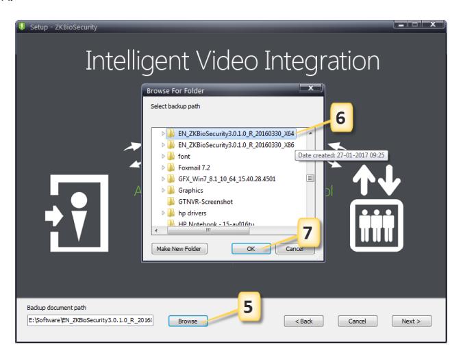
- 5. Click Browse and choose or create a folder to store your backup files.
- 6. Select/Create the required folder.
- 7. Click OK.
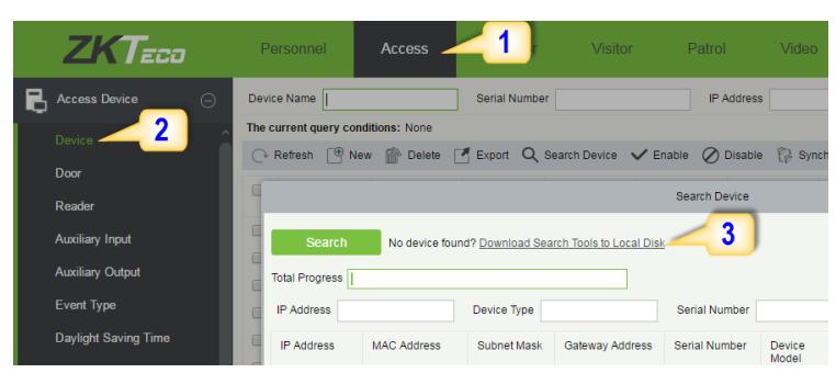
Adding Device
1. Click on Access to get below interface of Access Module of the software.
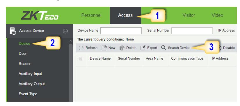
- 2. Click on Device.
- 3. Click on Search Device.
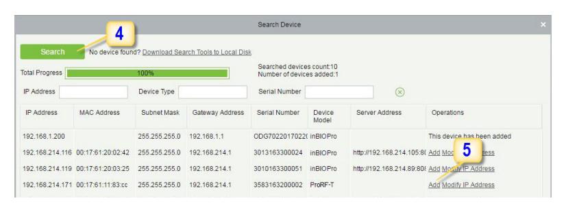
- 4. Click Search to search all the standalone devices on the network.
- 5. From the list, click Add to add the required device.
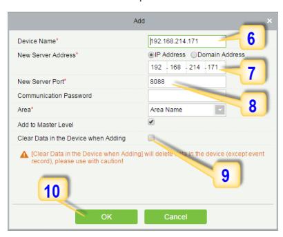
Adding Device
- 6. Enter a unique name.
- 7. Enter the IP address of current system (PC).
- 8. Enter the access point of system.
- 9. Click on this option, after adding device, the system will clear all data in the device (except the event logs).
- 10. Click OK to finish.
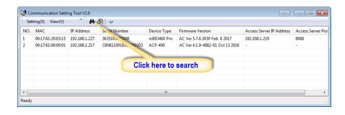
The default IP address may conflict with the device IP of other devices. In order to avoid that problem, modify the IP address as shown below:
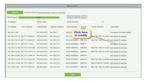
When the device is not in the same network with server, customers should download the tool and search the device as shown below:
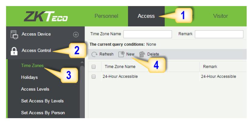
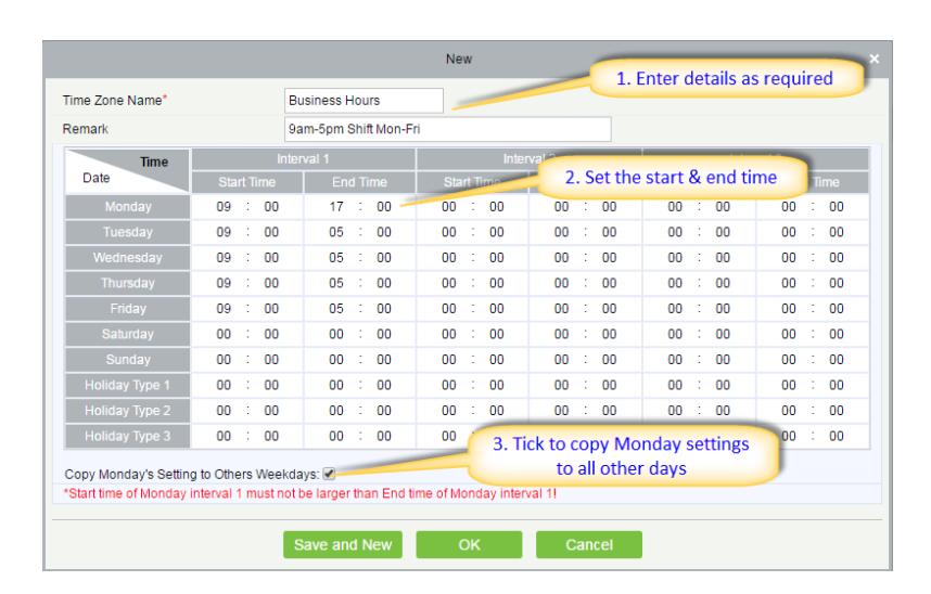
Creating a Time Zone
Click Access Control > Time Zones > Add to access the time zone setting interface.
After setting the time zone, click OK to save, and the time zone will appear in the list.
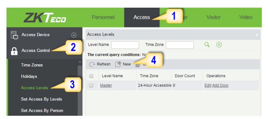
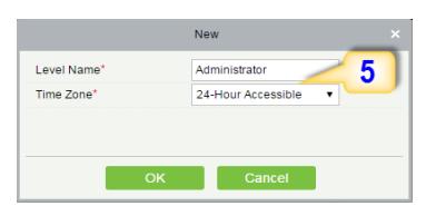
Creating an Access Level
1. Click Access 2. Click Access Control 3. Click Access Levels 4. Click New.

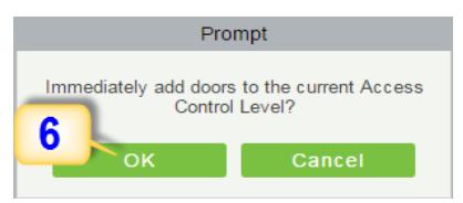
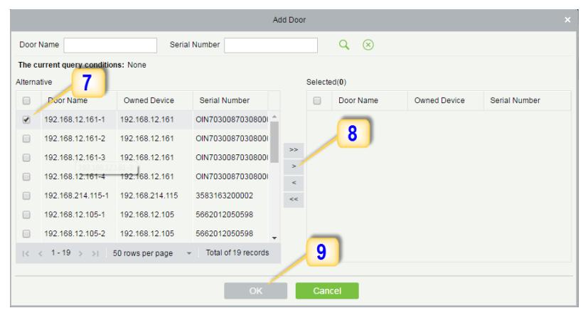
- 7. Select the required door(s).
- 8. Move the selected door(s).
- 9. Click OK to finish adding doors.
Enrolling Personnel
1. Click Personnel 2. Click Person 3. Click New to add personnel.
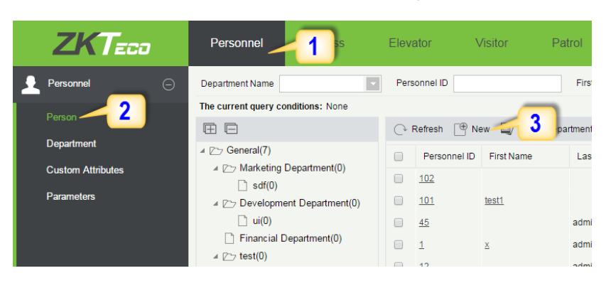
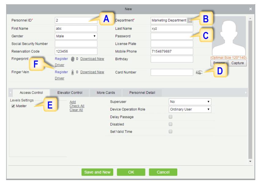
A. Personnel ID: It must be a unique 9 characters length with the valid range of 1-79999999. It can be configured based on actual conditions. The Personnel No. contains only numbers by default but may also include letters after setting parameters.
Enrolling Personnel
- B. Department: Select from the pull-down menu and click OK. If the department was not set previously, you can only select the default [Company Name] department.
- C. Password: Set personnel password. It only supports 6-digit passwords. If password exceeds the specified length, the system will truncate it automatically. It can't be same with duress or other passwords.
- D. Card Number: You can add a card number through manual entry or a card issuer. For issuing through issuer, click on the card icon directly. For issuing card manually, you must enter both the card number and the site code, then the software converts the numbers to the card number for access control system verification.
- E. Access Control: Here you will get all the access levels created by you and by default. Tick the required box.
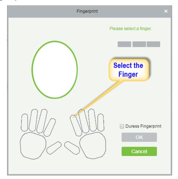
- F. Fingerprint: Enroll the Personnel Fingerprint or Duress Fingerprint. Duress Fingerprint is to trigger the alarm and send the signal to the system in case of emergency.
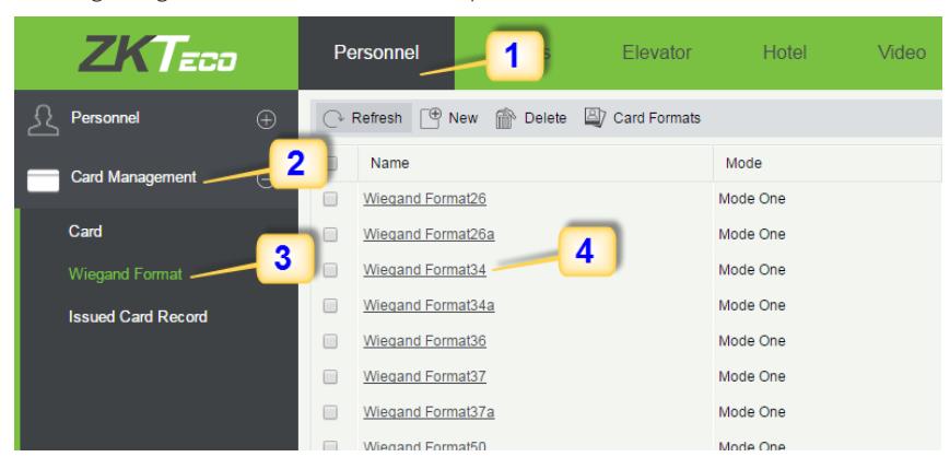
Wiegand Format
Wiegand Format is the card format that can be identified by Wiegand reader. The software is embedded with 10 Wiegand formats. You may set the Wiegand card format as required.
- 1. Click Personnel 2. Click Card Management 3. Click Wiegand Format.
- 4. Taking Wiegand Format34 as an example. Click to edit.
This software supports two modes for adding Wiegand Format, if mode 1 does not meet your setting requirement, switch to mode 2.
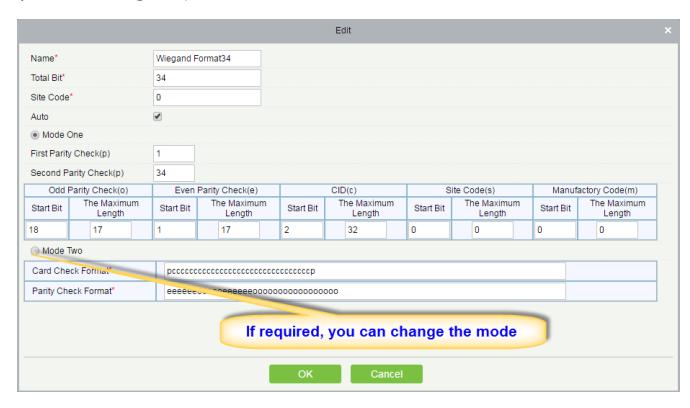
p indicates Parity Position, s indicates Site Code, c indicates Cardholder ID, f indicates Facility Code, m indicates Manufactory Code, e indicates Even Parity, O indicates Odd Parity, b indicates both odd check and even check, x indicates parity bits no check.
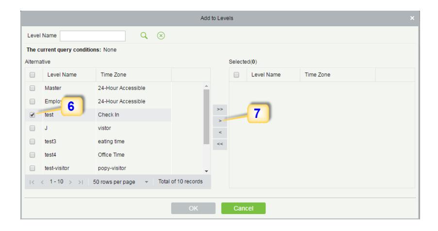
Add & Delete Personnel to Access Level
1. Click Access 2. Access Control 3. Set Access by Person 4. Click on the required employee 5. Click Add to Levels.
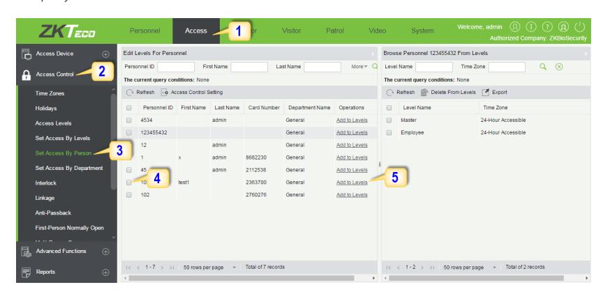
- 6. Select Level(s).
- 7. Click to move the selected level(s) to the right, and then click OK to complete adding. The added level(s) will appear in the list on to the right side.
Real -Time Monitoring
1. Click Access 2. Click Access Device 3. Click Real-Time Monitoring
Real-time monitor the status and real-time events of standalone in the system, including normal events and abnormal events (including alarm events) device transactions.
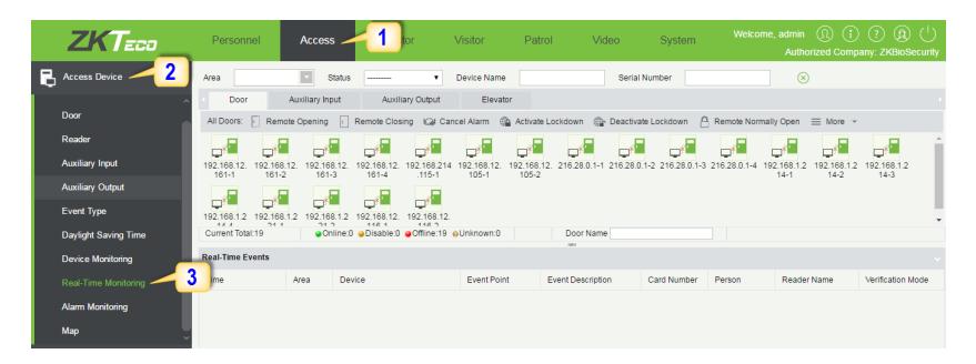
You can also filter by Area, device name, Serial number to check a specific device transactions or all at once.
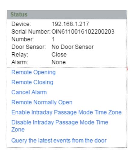
Hover over a door icon to open pop up menu as shown below and click Remote Closing, Remote Opening, or Cancel Alarm and more.
Exporting Reports
Access Module:
1. Click Access 2. Click Reports 3. Filter the data (time, Personnel ID, Device Name and more) if required and click on search 4. Click All transactions or as required.
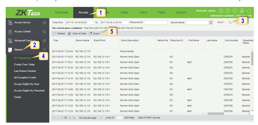
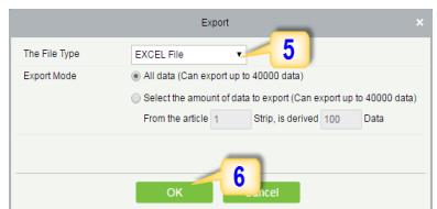
- 5. Click on Export to get the list.
- 6. Click OK.
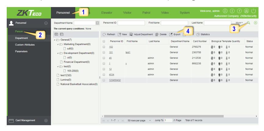
Personnel Module:
1. Click Personnel 2. Click Person 3. Filter the data (Department, Personnel ID, and more) if required and click on search 4. Click on Export to get the list.