ZKTeco USA FR1200 Installation Guide
Open the original PDF document
View PDFFR1200 Installation & Wiring Guide
Version:1.2
Date: Nov. 2011
1. Install Device

Post the mounting template on the wall. Drill the holes according to the marks on the template (holes for screws and wiring).
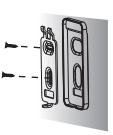
(4) Fix the plastic pad and the back plate on the wall accord -ing to the mounting paper.
(2) Remove the screw on the bottom of device.
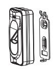
(3) Take away the back plate.
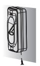
(5) Tighten the screw on the bottom, fix the device to the back plate.
The device can only be used as reader. It cannot dispose the obtained information. Therefore, it needs connecting host machine to obtain fingerprint information and transmit it to host machine for disposal through RS485. The host machine is specified access control terminal which you can consult the commercial representative. Please power off the device before connection. Connection under power-on state may bring great damage to the device.
Note:
- a. Please keep the distance between the device and control panel or standalone access control less than 90 meters (Please use Wiegand signal extender in long distance or interference environment).
- b. To keep the stability of Wiegand signal, connect the device and the control panel or access control in same 'GND' in any case.
(2) Connection With Standalone Access Control
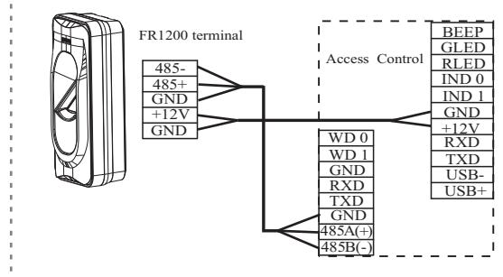
(3) The terminal definition table of Reader
| NO. | Terminal name | Function | |
|---|---|---|---|
| 1 | 485- | 485 communication- | |
| 2 | 485+ | 485 communication+ | |
| 3 | GND | Signal GND | |
| 4 | +12V | 12V power output | |
| 5 | GND | Power GND | |
The terminal definition table of the host machine
| NO. | Terminal name | Function | ||
|---|---|---|---|---|
| 1 | BEEP | Signal output of buzzer | ||
| 2 | GLED | Signal output of green indicator | ||
| 3 | RLED | Signal output of red indicator | ||
| 4 | IND 0 | Wiegand D0 input | ||
| 5 | IND 1 | Wiegand D1 input | ||
| 6 | GND | GND | ||
| 7 | +12V | 12V power output | ||
| 8 | RXD | RS 232 input | ||
| 9 | TXD | RS 232 output | ||
| 10 | USB- | USB communication- | ||
| 11 | USB+ | USB communication+ | ||
| NO. | Terminal name | Function | |
|---|---|---|---|
| 1 | WD 0 | Wiegand D0 output | |
| 2 | WD 1 | Wiegand D1 output | |
| 3 | GND | GND | |
| 4 | RXD | RS 232 input | |
| 5 | TXD | RS 232 output | |
| 3 | GND | GND | |
| 4 | 485A(+) | 485 communication+ | |
| 5 | 485B(-) | 485 communication- | |
2. Work Principle
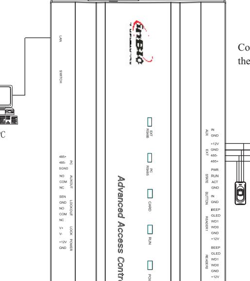
(1) Connection With Control Panel
Connected as in BIO Reader (with External 485), the maximum can connecting
Access Control Panel
3. Other Functions
(1) Wiring Terminals of Control Panel: (As the figure 1 below)

| Address | Switch Setting Address | Switch Setting | |
|---|---|---|---|
| 1 |
ON
1 4 6 2 3 5 |
5 |
ON
1 2 3 4 5 6 |
| 2 |
ON
1 4 6 2 3 5 |
6 |
ON
1 2 3 4 5 6 |
| 3 |
ON
4 1 2 3 5 6 |
7 |
ON
1 4 2 3 5 6 |
| 4 |
ON
4 1 2 3 5 6 |
8 |
ON
1 2 3 4 5 6 |
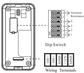
Dip Switch Setting(figure 2)
Dip Switch Setting: (As the figure 2 above)
Number 5 switch is idle. It is adopted binary coding and little endian. Number 1-4 switches are used to set the 485 address number (device number). The address number setting by place these 4 switches are shown as the figure 2 above.
Number 6 switch is used to set the terminal resistance inRS485 communication: If the 485 communication wire is longer, than100 meters, it is needed to set the number 6 dip switch of the last reader to ON state, that is parallel a terminal resistance of 120 ohm between 485+ and 485-.
(2) Wiring Terminals of Access Control : (As the figure 3 below).
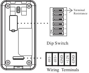
Back View ( figure 3)
Reset Switch
Bottom View (figure 4)
When using it, please move the dial code address "1" to the "ON" position.
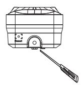
(3) Reset Switch (As the figure 4 above).
If the device does not work properly because of misoperation or other abnormalities, you can use 'Reset' function to restart it.
Operation: Remove the black rubber cap,then stick the Reset button hole with a sharp tool(diameter is less than 2mm).
(4) Verification Process
Press finger or flash card on the device. When the device gets the information, it will transmit the information to the host machine, which will verify fingerprint or card. Then corresponding prompt will be given and transmitted to the device.
- ①. Green light twinkle: normal standby state.
- ②. Green light on, and the buzzer "Dii…": success in card or fingerprint verification.
- ③. Red light on, and the buzzer " Dii…Dii…" : failure in card or fingerprint verification.
- ④. Red light on, and the buzzer " Dii…" for three time: card or fingerprint is unauthorized.
- ⑤. Red light on, and the buzzer " Dii…" for four time: communication is abnormal between r eader and access control device.
4. Cautions
- (1) Power cable is connected after all the other wiring.If the device is operated abnormally, please shut down the power firstly, then make some necessary checking.Kindly remain that any hot-plugging may damage device, and it is not included in the warranty.
- (2) We recommend that use access control device power supply for the reader. Specification is equal or greater than AWG22, and the distance is less than 200 meters. If the distance is more than 200 meters, please use DC 1.5A/12V independent power supply. But to the Control Panel, We recommend that use the DC 3A/12V power supply.
- (3) Please read the terminals description carefully and wiring by rule strictly. Any damage caused by improper operations will be out of the range of our guarantee.
- (4) Keep the exposed part of wire is less than 5mm to avoid unexpected connection, and result in machinery damage.
- (5) Please connect the 'GND' before all the other wiring especially under the serious electrostatic environment, to prevent the overlarge instantaneous electrostatic to damage device.
- (6) If the power supply is a little long, please do not use the Internet or other cable instead. When choosing the power supply cable, you should consider that the transmission voltage attenuation. distance between and device cable types of distance may cause
