ZKTeco USA F18 Installation Guide
Open the original PDF document
View PDF


www.zkaccess.com

| Safety Precautions | 02 |
|---|---|
|
How
to place a finger |
04 |
| Product Contents | 07 |
|
Product
PIN Diagram |
09 |
|
Product
Dimensions |
11 |
| Cables and Connectors | 12 |
|
Installation
of Back Plate |
13 |
| Power Connection | 14 |
|
Ethernet
Connection |
15 |
|
PC
RS485 Connection |
17 |
|
FR1200
RS485 Connection |
18 |
|
Lock Relay
Connection |
19 |
|
Weigand
Input Connection |
21 |
|
Weigand
Output Connection |
22 |
|
Installation
Reference |
23 |
| Specifications | 26 |
|
Electrical
Specifications |
27 |
| Troubleshooting | 28 |
1Safety Precautions
The following precautions are to keep user's safe and prevent any damage. Please read carefully before installation.

Do not install the device in an area subject to direct sunlight, humidity or dust

Be careful not to let liquid like water, drinks or chemicals leak inside the device.

Do not place a magnet near the product. Magnetic field from magnets, CRT, TV, monitor or speaker may damage the device.

Clean the device often to remove dust on it

Do not place the device next to heating equipment.

Do not let children touch the device without supervision.
1Safety Precautions
The following precautions are to keep user's safe and prevent any damage. Please read carefully before installation.


Do not damage the device

Do not drop the device. Do not use the device for any Do not disassemble, repair or alter the device.

In cleaning, do not splash water on the device but wipe it out with smooth cloth or towel.
other purpose than specified.

Contact your nearest dealer in case of a trouble or problem.
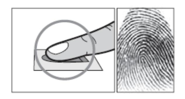
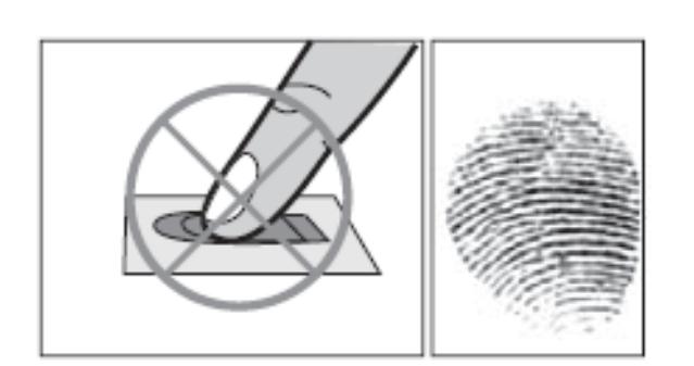
1How to Place a Finger
ZkTeco's fingerprint readers will give optimal results for fingerprint matching if the following recommendations and suggestions are followed.
Select a finger to enroll
- It is recommended to use an index finger or a middle finger.
- Thumb, ring or little finger are relatively difficult to place in the correct position
How to place a finger on a sensor
- Place a finger such that it completely covers the sensor area with maximum contact.
-
Place core of the fingerprint at the center of the sensor. The core of a fingerprint is a center where the spiral of ridges is dense.
- Usually core of fingerprint is the opposite side of the lower part of a nail.
- Place a finger such that the bottom end of a nail is located at the center of a sensor.
- If a finger is placed as shown in the right, only a small area of a finger is captured. So it is recommended to place a finger as shown on the left.
1How to Place a Finger
Tips for different fingerprint conditions
-
ZKTeco's fingerprint products are designed to verify fingerprints with highest security irrespective of the conditions of the skin of the finger. However, in case a fingerprint is not read on the sensor, please refer to the followings tips.
- If a finger is stained with sweat or water, scan after wiping moisture off.
- If a finger is covered with dust or impurities, scan after wiping them off.
- If a finger is way too dry, please blow some warm air from your mouth on the finger tip.
Tips for fingerprint enrollment
- In fingerprint recognition, enrollment process is very important. When enrolling a fingerprint, please try to place the finger correctly with utmost care.
-
In case of low acceptance ratio, the following actions are recommended.
- Delete the enrolled fingerprint and re-enroll the finger.
- Enroll the same fingerprint again.
- Try another finger if a finger is not easy to enroll due to scar or cuts.
- In case of an enrolled fingerprint cannot be used due to injury or if the hand is full, it is recommended to enroll more than two fingers per user.
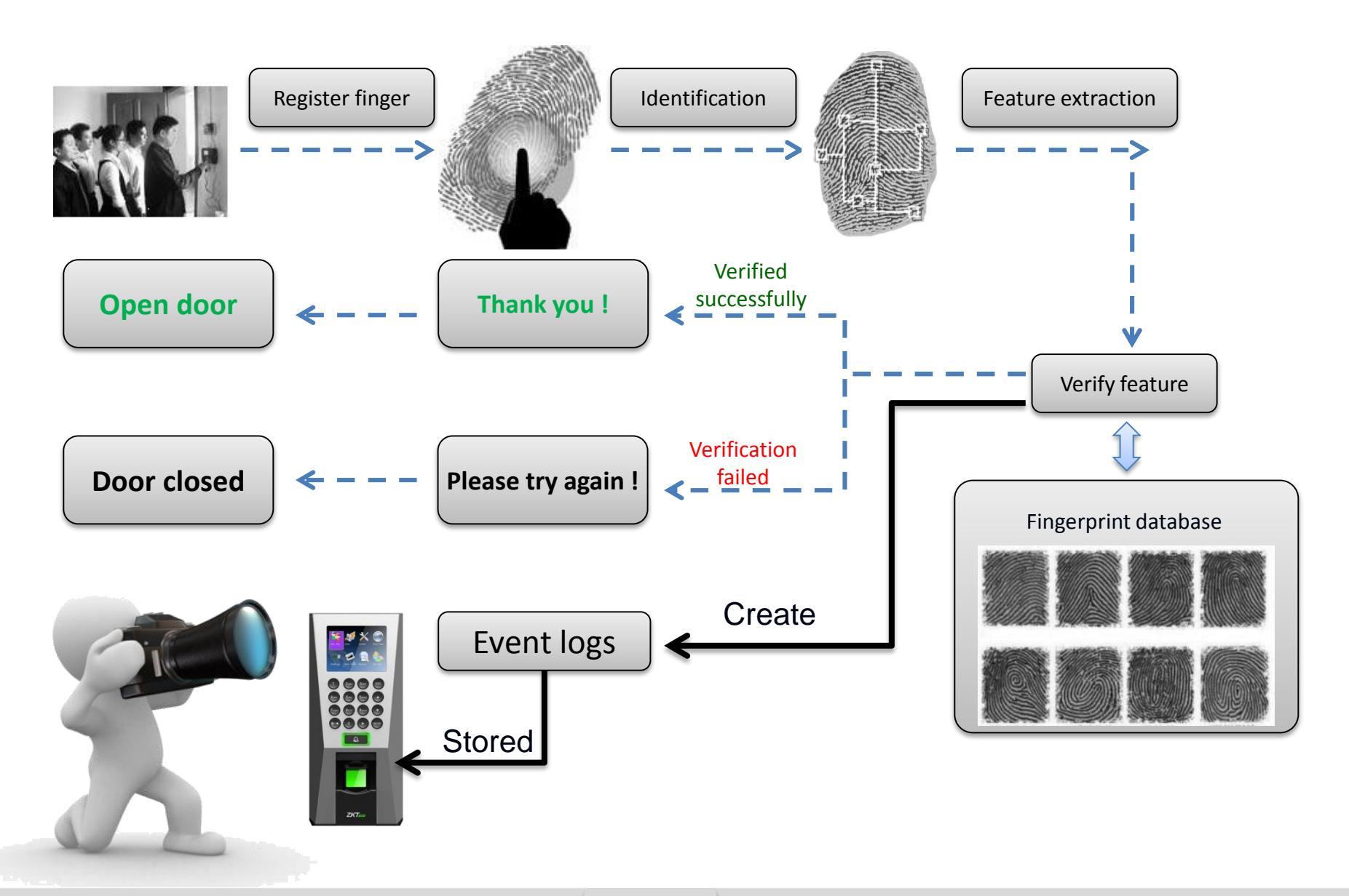
1How Does F18 work
Product Contents
Basic Contents


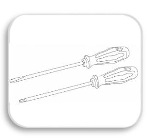


Screw Driver – 2 pcs. Wall Mounting Screws – 4 pcs. Wall Plugs– 4 pcs
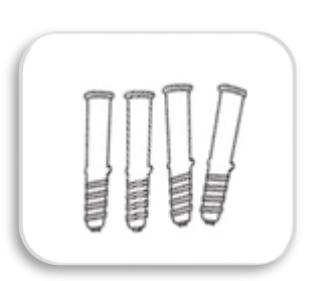

Star-shape Screw for Mounting Plate -2 pcs
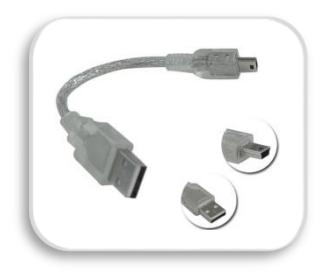
Mini-USB Cable -1 pcs
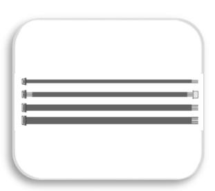
2 pin, 4 pin, 7 pin, 8 pin, 10 pin cables – each 1 pcs Metallic Mounting Paper Back Plate

F18
Product Contents
Optional accessories

Weigand Card Reader

RS485 Convertor

FR1200 Slave Fingerprint Reader

Prox Card

12VDC, 3A Power Adaptor
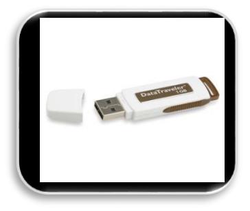
USB Memory

K1-1 Exit Button

Alarm
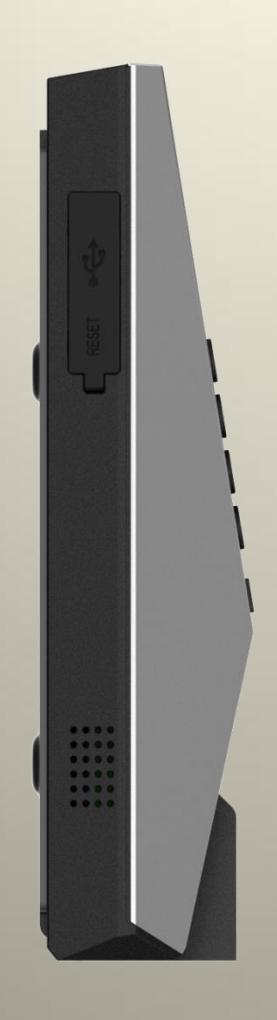
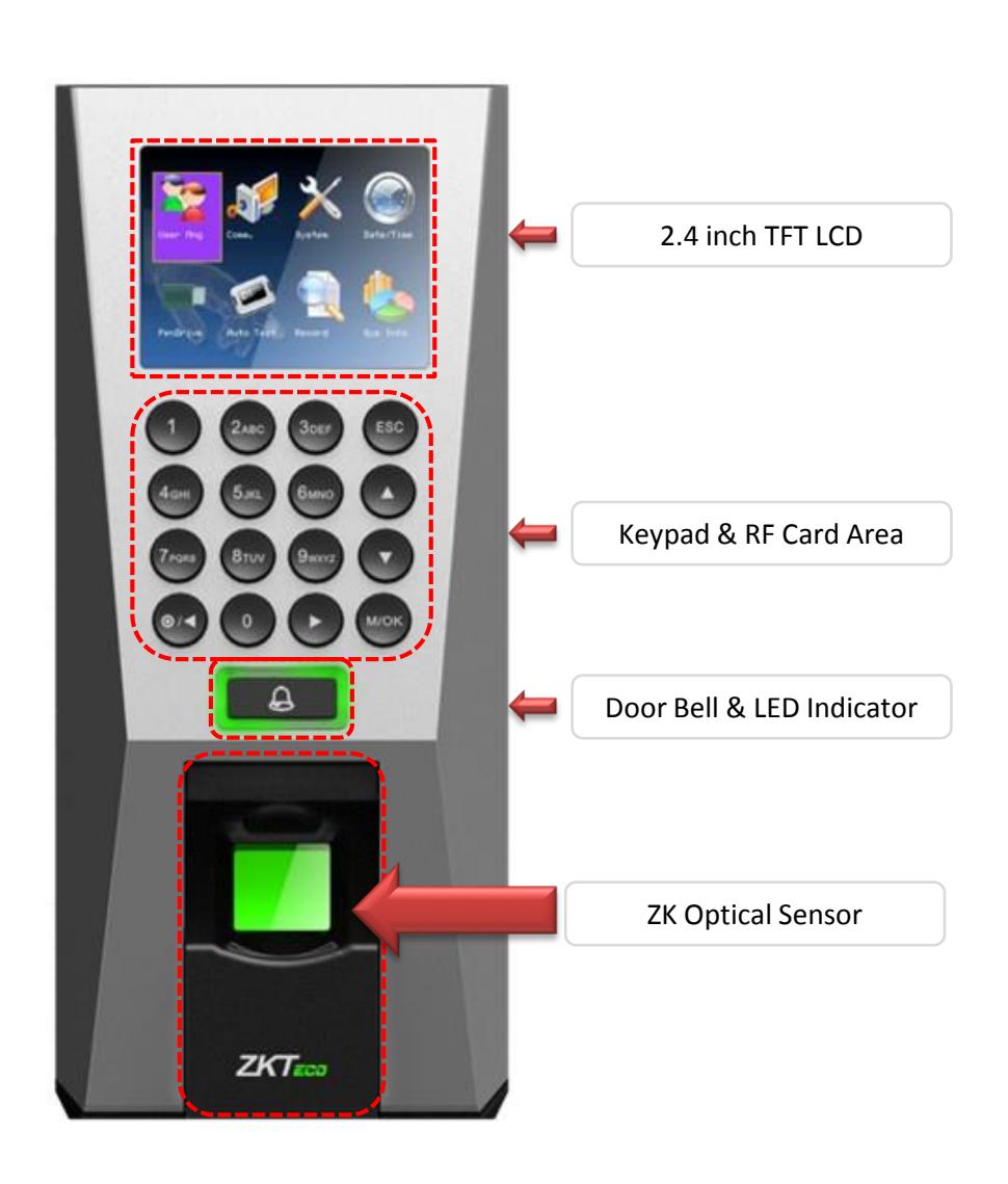
Product PIN Diagram
Front
Side
Product PIN Diagram
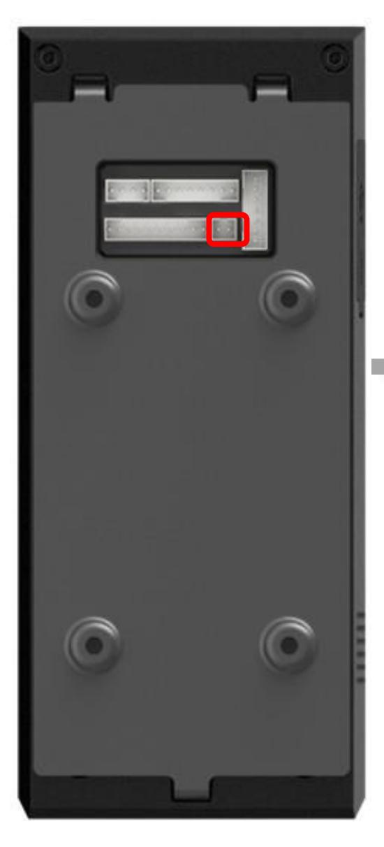
Bottom
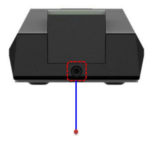
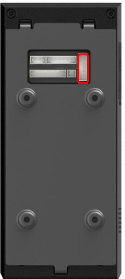
Star-shaped screw hole for fixing reader to the back plate
Back
Product Dimension
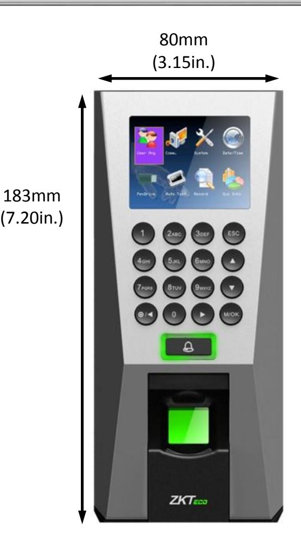
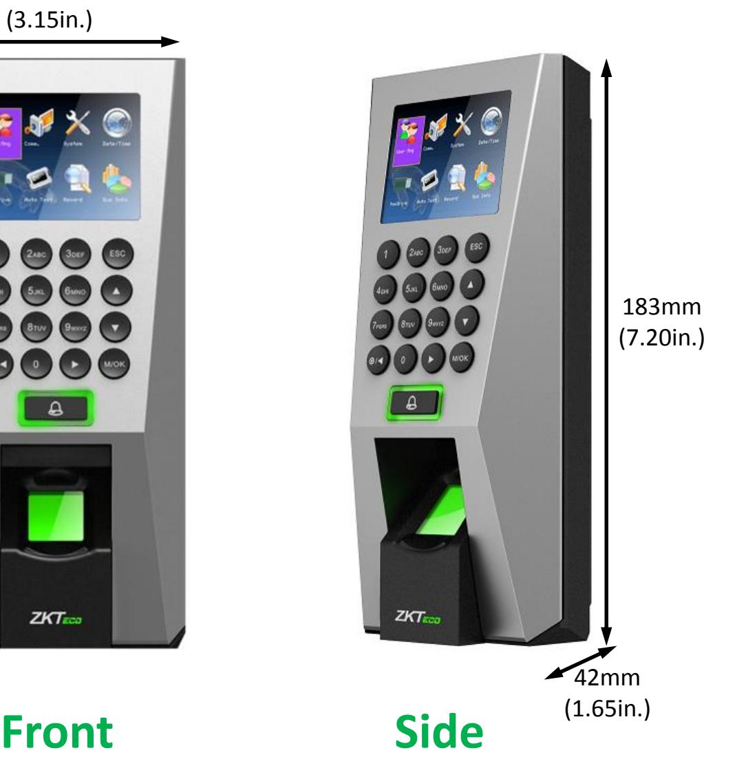
183mm (7.20in.) 80mm (3.15in.)
Back Plate
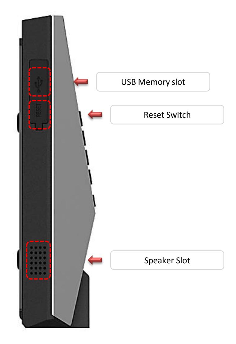
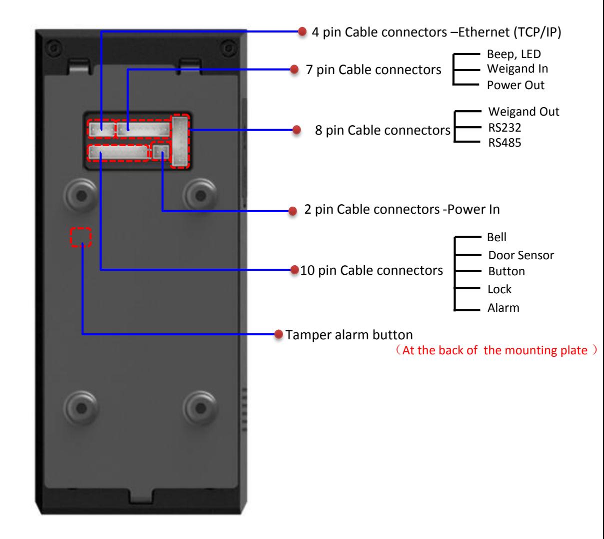
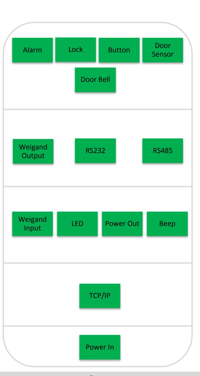
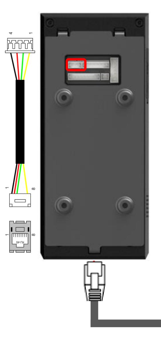
Cables and Connectors

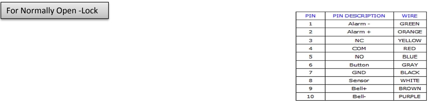
| PIN | PIN DESCRIPTION | WIRE |
| 1 | Alarm - | GREEN |
| 2 | Alarm + | ORANGE |
| 3 | NC | YELLOW |
| 4 | СОМ | RED |
| 5 | NO | BLUE |
| 6 | Button | GRAY |
| 7 | GND | BLACK |
| 8 | Sensor | WHITE |
| 9 | Bell+ | BROWN |
| 10 | Bell- | PURPLE |
| PIN | PIN DESCRIPTION | WIRE |
| 1 | WD0 | GREEN |
| 2 | WD1 | WHITE |
| 3 | GND | BLACK |
| 4 | 232 RX | GRAY |
| 5 | 232 TX | PURPLE |
| 6 | GND | BLACK |
| 7 | 485 A | BLUE |
| 8 | 485 B | YELLOW |
| PIN | PIN DESCRIPTION | WIRE |
| 1 | BEEP | PURPLE |
| 2 | GLED | GRAY |
| 3 | RLED | BLUE |
| 4 | INWD0 | GREEN |
| 5 | INWD1 | WHITE |
| 6 | GND | BLACK |
| 7 | +12V | RED |
| PIN | PIN DESCRIPTION | WIRE |
|---|---|---|
| 1 | RJ45-1 | YELLOW |
| 2 | RJ45-2 | GREEN |
| 3 | RJ45-3 | RED |
| 4 | RJ45-6 | BLACK |
| PIN | PIN DESCRIPTION | WIRE |
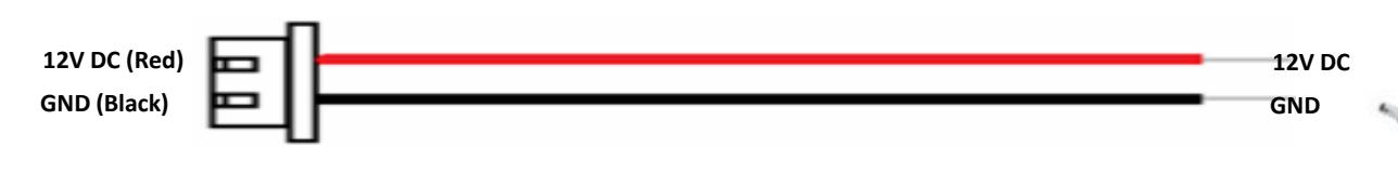
|---|---|---|
| 1 | +12V DC | RED |
| 2 | GND | BLACK |
Installation of Wall-mount
Fix back plate to the wall using wall mounting screws
- Mount F18 terminal on the Back plate
- Secure F18 and back plate using a star shape screw.
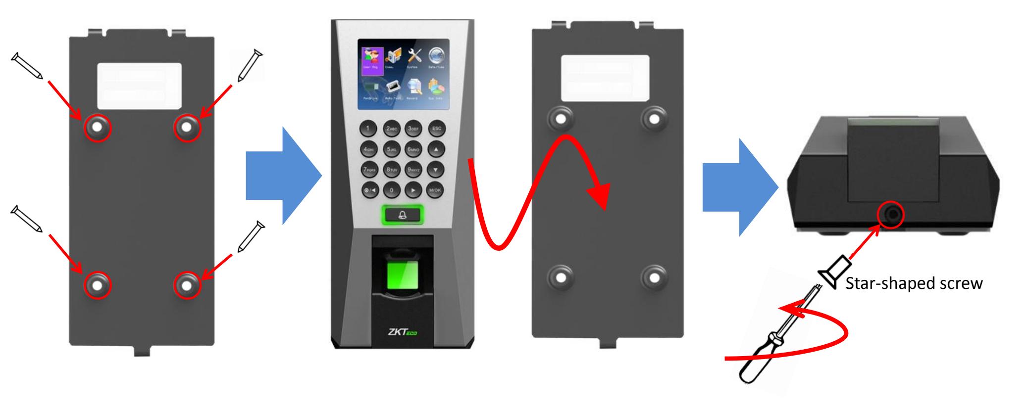
Wall mounting screws
Star-shaped screw driver
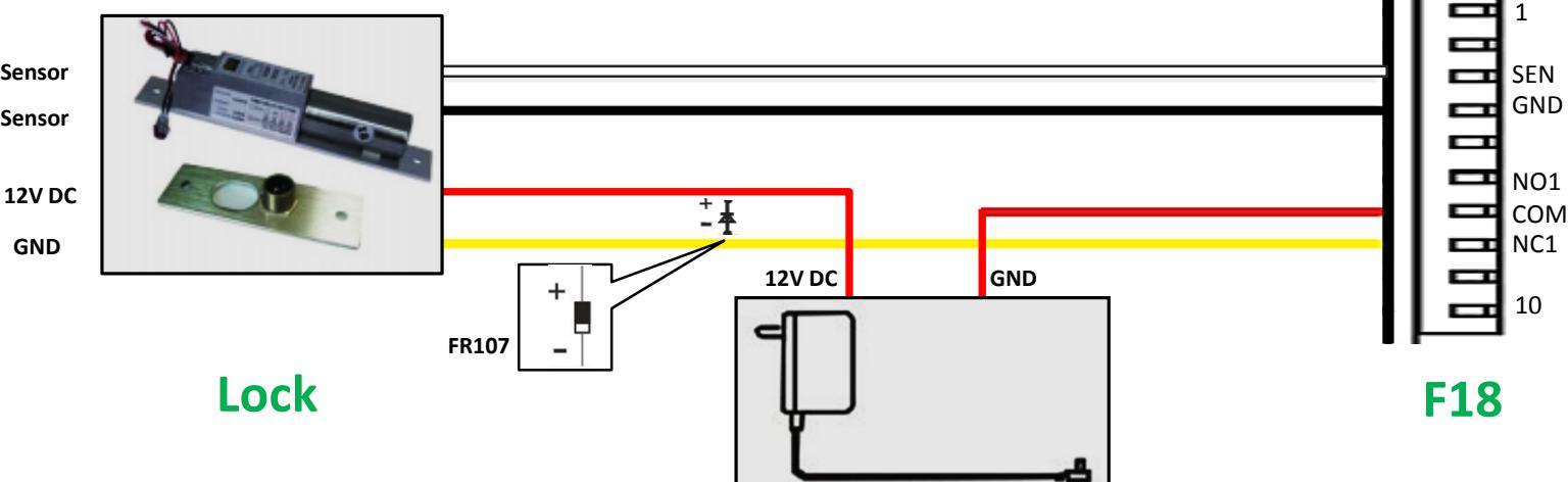
Power Connection

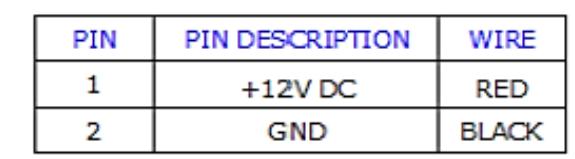


- Recommended power supply
- 12V ± 10%, at least 500mA.
- Comply with standard IEC/EN 60950-1.
- To share the power with other devices, use a power supply with higher current ratings
Ethernet Connection

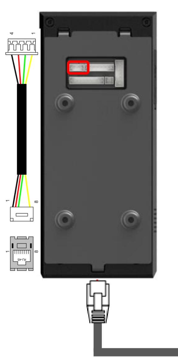
| PIN | PIN DESCRIPTION | WIRE |
|---|---|---|
| 1 | RJ45-1 | YELLOW |
| 2 | RJ45-2 | GREEN |
| 3 | RJ45-3 | RED |
| 4 | RJ45-6 | BLACK |

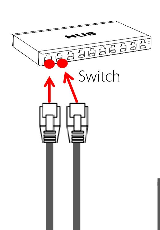
TCP/IP TCP/IP
Ethernet Connection
Direct Connection to PC
| PIN | PIN DESCRIPTION | WIRE |
|---|---|---|
| 1 | RJ45-1 | YELLOW |
| 2 | RJ45-2 | GREEN |
| 3 | RJ45-3 | RED |
| 4 | RJ45-6 | BLACK |

16
TCP/IP
PC RS485 Connection

PC RS485 Connection
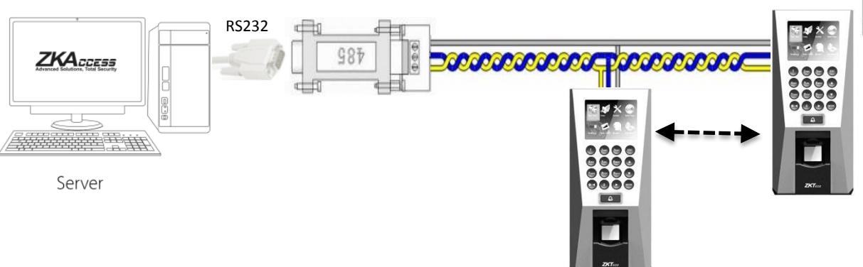
| PIN | PIN DESCRIPTION | WIRE |
|---|---|---|
| 1 | WD0 | GREEN |
| 2 | WD1 | WHITE |
| 3 | GND | BLACK |
| 4 | 232 RX | GRAY |
| 5 | 232 TX | PURPLE |
| 6 GND | BLACK | |
| 7 | 485 A | BLUE |
| 8 | 485 B | YELLOW |

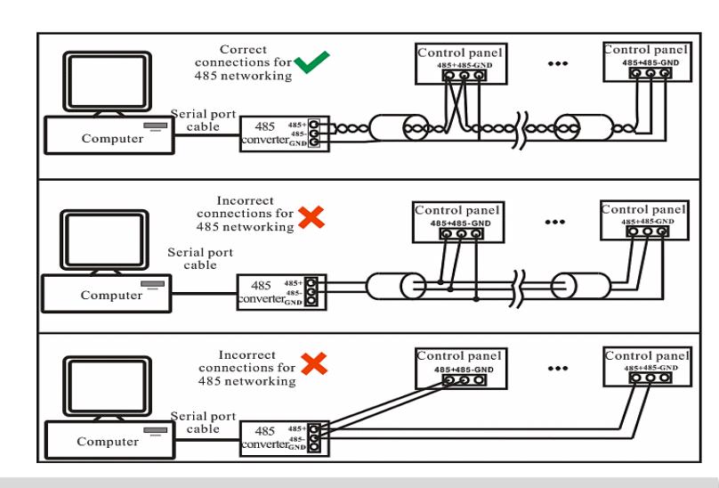
- 1. RS485 communication wires should be a shielded or twisted pair cable. RS485 communication wires should be connected in a bus cascade instead of a star form, to achieve a better shielding effect by reducing signal reflection during communications.
- 3. Adjust the communication speed as needed , The signal quality vary depending on wiring conditions, and it maybe necessary to lower the baudrates.
- 4. The GND Signal may be omitted if and only if the GND potential difference is less than ±5V
Important Notes Do's and Dont's for RS485 connection
FR1200 RS485 Connection

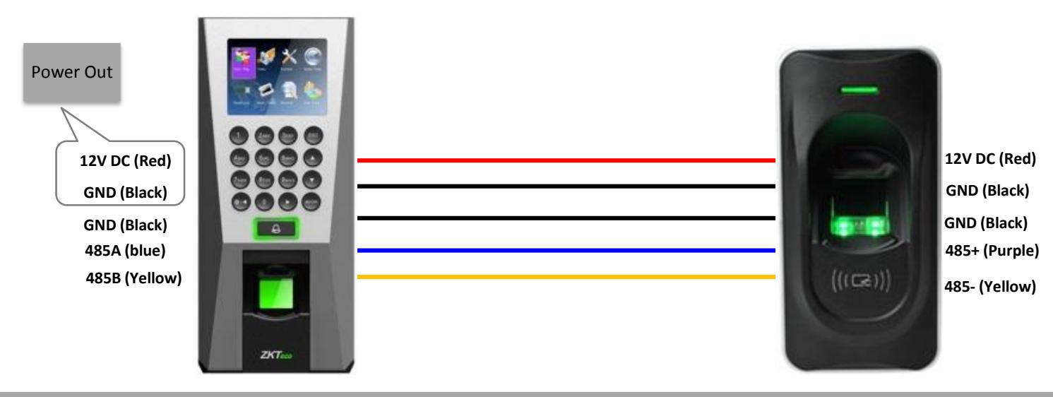
Important Notes
- 1.Steps to activate the master and salve functionality between F18 and FR1200 is shown in the diagram on the left.
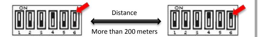
- 2. There are six DIP switches on the back of FR1200 , Switches
- 1-4 is for RS485 address , switch 5 is reserved , switch 6 is for reducing noise on long RS485 cable.
- 3. If FR1200 is powered from F18 terminal ,the length of wire should be less than 100 meters or 330 ft.
- 4. If the cable length is more than 200 meters or 600 ft. , the number 6 switch should be ON as below
Lock Relay Connection


Lock Relay Connection


| PIN | PIN DESCRIPTION | WIRE |
| 1 | Alarm - | GREEN |
| 2 | Alarm + | ORANGE |
| 3 | NC | YELLOW |
| 4 | СОМ | RED |
| 5 | NO | BLUE |
| 6 | Button | GRAY |
| 7 | GND | BLACK |
| 8 | Sensor | WHITE |
| 9 | Bell+ | BROWN |
| 10 | Bell- | PURPLE |
Weigand Input Connection

| PIN | PIN DESCRIPTION | WIRE |
| 1 | BEEP | PURPLE |
| 2 | GLED | GRAY |
| 3 | RLED | BLUE |
| 4 | INWD0 | GREEN |
| 5 | INWD1 | WHITE |
| 6 | GND | BLACK |
| 7 | +12V | RED |
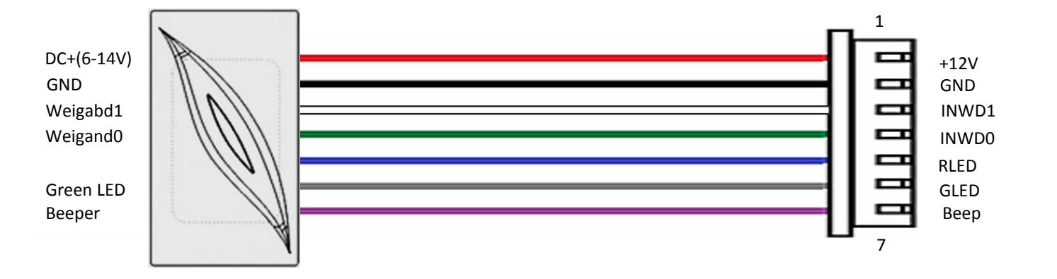
Weigand Card Reader
F18
Weigand Output Connection
| PIN | PIN DESCRIPTION | WIRE |
| 1 | WD0 | GREEN |
| 2 | WD1 | WHITE |
| 3 | GND | BLACK |
| 4 | 232 RX | GRAY |
| 5 | 232 TX | PURPLE |
| 6 | GND | BLACK |
| 7 | 485 A | BLUE |
| 8 | 485 B | YELLOW |
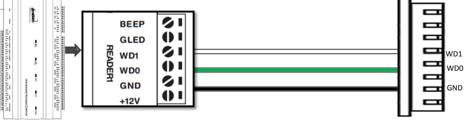
Access controller F18
Installation Reference
Standalone
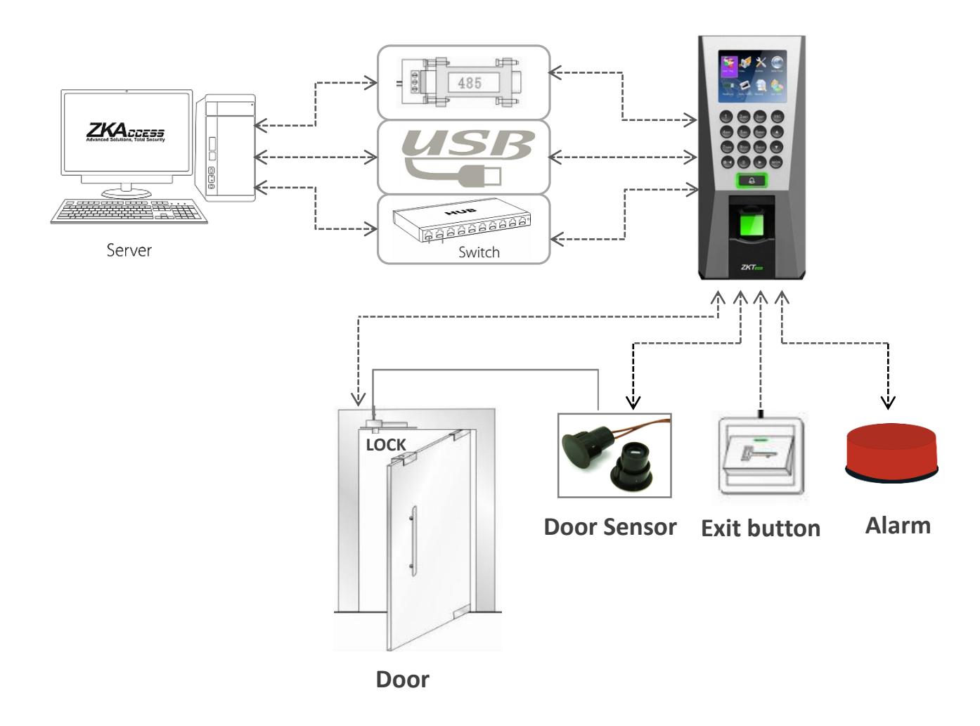
Installation Reference
Third Party Controller
Weigand Output Connection
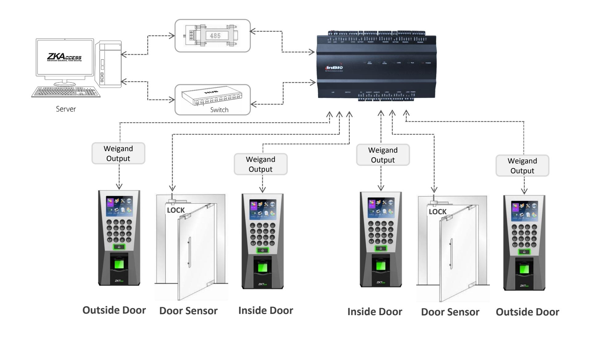
Installation Reference
Third Party Controller
RS485 Connection

Specification
| Item | Specification | |
|---|---|---|
| Fingerprint capacity | 3,000 | |
| Transaction capacity | 100,000 | |
| Hardware Platform | ZEM720 | |
| CPU | ZK 6001, 400Mhz | |
| Memory | 64M Flash, 32MSDRAM | |
| Fingerprint Sensor | ZK optical sensor | |
| Display | 2.8" TFT LCD color screen | |
| LED Indicator | Red, Green | |
| Communication | Ethernet(10/100M), RS485, USB-HOST, | |
|
Weigand
signal |
Wiegand Input and Wiegand Output | |
| Identification speed | ≤2 sec | |
| FAR | ≤0.0001% | |
| FRR | ≤1% | |
| Operating Temperature | 0-45℃ | |
| Operating Humidity | 20%-80% | |
| Language | English, Spanish, Portuguese, French… | |
| Power Supply | 12V DC, 3A | |
| Access control interfaces | Electric lock, alarm, exit button, wired door bell | |
| Dimension | 80*183*42mm (L*W*D) | |
Electrical Specification
| Min. | Typ. | Max. | Notes | ||
|---|---|---|---|---|---|
| Working power supply | |||||
| Voltage(V) | 9.6 | 12 | 14.4 | Use regulated DC power adaptor only | |
| Current(A) | 2 | ||||
| Electronic lock relay output | |||||
| Switching voltage(V) | 36V | Use regulated DC power adaptor only | |||
|
Switching
Current(A) |
2 | ||||
| Switch Aux. input | |||||
| VIH (V) | TBD | ||||
| VIL (V) | TBD | ||||
| Pull-up resistance (Ω) | 4.7k | The input ports are pulled up with 4.7k resistors | |||
| WEIGAND Input | |||||
| Voltage(V) | 10.8 | 12 | 13.5 | ||
| Current(mA) | 500 | ||||
| TTL/WEIGAND Output | |||||
|
VoH
(V) |
5 | ||||
|
VoL
(V) |
0.8 | ||||
| Pull-up resistance (Ω) | 4.7K |
The outputs ports are open drain type, pulled up with 4.7k
resistors internally |
|||
|
ZK Electronic
lock |
|||||
| Voltage(V) | 10.8 | 12 | 13.2 | ||
| Current(mA) | 500 | ||||
Troubleshooting
-
Fingerprint can not be read or it takes too long.
- Check whether a finger or fingerprint sensor is stained with sweat, water, or dust
- Retry after wiping off finger and fingerprint sensor with dry paper tissue or a mildly wet cloth.
- If a fingerprint is way too dry, blow on the finger and retry.
-
Fingerprint is verified but authorization keeps failing.
- Check whether the user is restricted by door zone or time zone.
- Check with administrator whether the enrolled fingerprint has been deleted from the device for some reason.
-
Authorized but door does not open.
- Check whether the lock duration is set to appropriate minutes which opens the lock.
- Check whether anti-passback mode is in use. In anti-passback mode, only the person who has entered through that door can exit.
-
Why device display "system broken" and the alarm is ringing.
- Check whether the device and back plate are securely connected to each other. If not, a tamper switch is activated which triggers the alarm and keeps it ringing.
-
How to set F18 used as fingerprint reader on Inbio access controller.
- Please contact our technical support department


Copyright 2013 ZKTeco Inc. All right reserved.
ZKTeco May, at any time and without notice , Make changes or improvements to the product and services offered and/or cease producing or commercializing them.
ZK USA office:
201 Circle Drive North, Suite 116 Piscataway, NJ 08854, USA
Tel: +1 732-412-6007
Fax +1 732-412-6008
sales@zkaccess.com
zkaccess.com
Functions and specifications of the product are subject to change without notice due to quality enhancement or function update. For any inquiry for the product, please contact ZKACCESS.