ZKTeco USA Atlas Installation Guide
Open the original PDF document
View PDFInstallation Guide
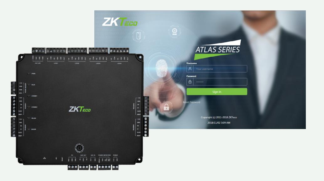
Atlas x00 Series
Access Control Panels

What's in the Box
CONTENTS
| What's in the Box | 2 |
|---|---|
| Optional Accessories | 4 |
| Safety Precautions | 5 |
| Product PIN Diagram | 6 |
| LED Indicators | 7 |
| Product Dimension | 8 |
| Installation of Panel & Cabinet | 9 |
| Wiring Legend | 10 |
| Power Wiring Diagram | 11 |
| Wiegand Connection | 12 |
| OSDP Connection | 13 |
| REX Connections | 14 |
| Lock Connection | 15 |
| AUX. I/O Connection | 16 |
| Ethernet Connection | 17 |
| Typical Installation | 18 |
| Troubleshooting | 19 |
| Electrical Specifications | 20 |
| Introduction | 23 |
| Understanding the Atlas Series Network | 24 |
| Initial Controller Setup | 25 |
| Connect the Controller to the Network | 31 |
| Complete the Configuration | 32 |
| Add a User and Test Access | 36 |
| Add Secondary Controllers | 38 |
| Mobile App | 39 |
| Special Considerations for Complex Networks | 43 |
| Where to Go Next | 43 |

Web Management Application Programming Guide starts at page 22
Optional Accessories
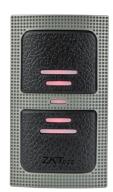
Wiegand Card Reader Prox Card

Door Sensor Exit Button
Alarm
CR10E Card Enroller
Atlas x00 Series Metal Cabinet
Safety Precautions
The following precautions are to keep user's safe and prevent any damage. Please read carefully before installation.


Do not expose to direct sunlight, water, dust and soot.

Do not place any magnetic objects near the product. Magnetic objects such as magnets, CRT, T V, monitors or speakers may damage the device

Do not place the device next to heating equipment.

Prevent water, drinks or chemicals leaking into the device.

This product is not intended for use by children unless they are supervised.

Do not drop or damage the device.

Do not disassemble, repair or modify the device.

Do not use the device for any purpose other than those specified.

Remove dust or dirt regularly. While cleaning, wipe dust off with a smooth cloth or towel instead of water.
Contact your supplier in case of any problem!
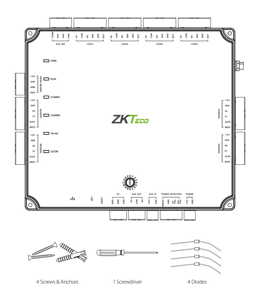
Product PIN Diagram
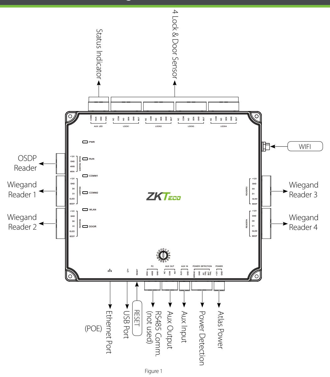
- The function of reset button (once reset button is pressed, LED will blink fast): 1. Press reset button for about 2-5 seconds, zk firmware will check if there is a USB disk which stores an upgrade package inserted into controller, if yes, then controller will do firmware upgrade automatically.
- 2. Press reset button for about 5-10 seconds, zk firmware will temporarily set IP to default 169.254.202.242.
LED Indicators
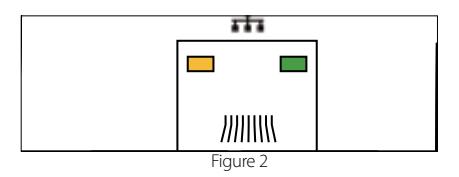
LINK Solid Green LED indicates TCP/IP communication is normal
Flashing (ACT )Yellow LED indicates data communication is in progress
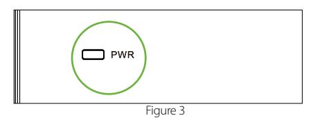
Solid (POWER) Red LED indicates the panel is powered on.
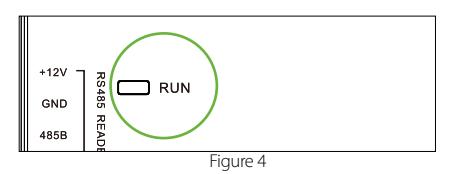
Flashing (RUN) Green LED indicates that panel is in normal working state.
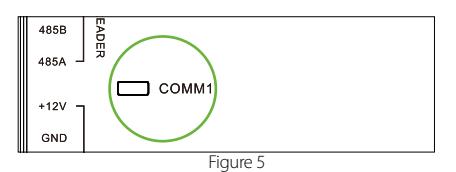
COMM1 Flashing Yellow indicates the system is communicating with upper-level devices (for example, the PC).(NOT USED)
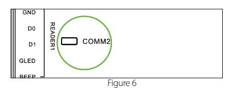
COMM2 Flashing Yellow indicates the system is communicating with lower-level devices (for example, readers).
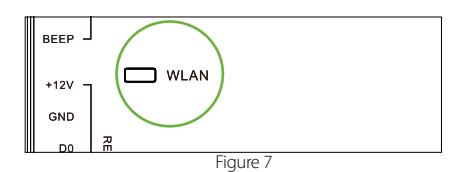
Flashing (WLAN) Green LED indicates the system is communicating in wireless (Wi-Fi) mode.
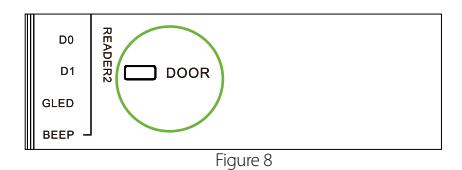
Flashing (DOOR) Green LED indicates a door opening signal (a door is opened).
Product Dimension
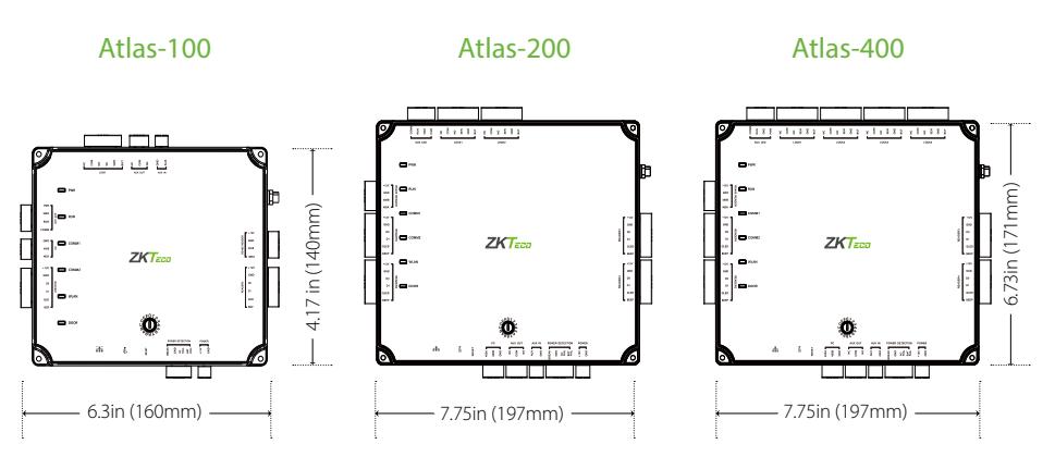
Figure 9
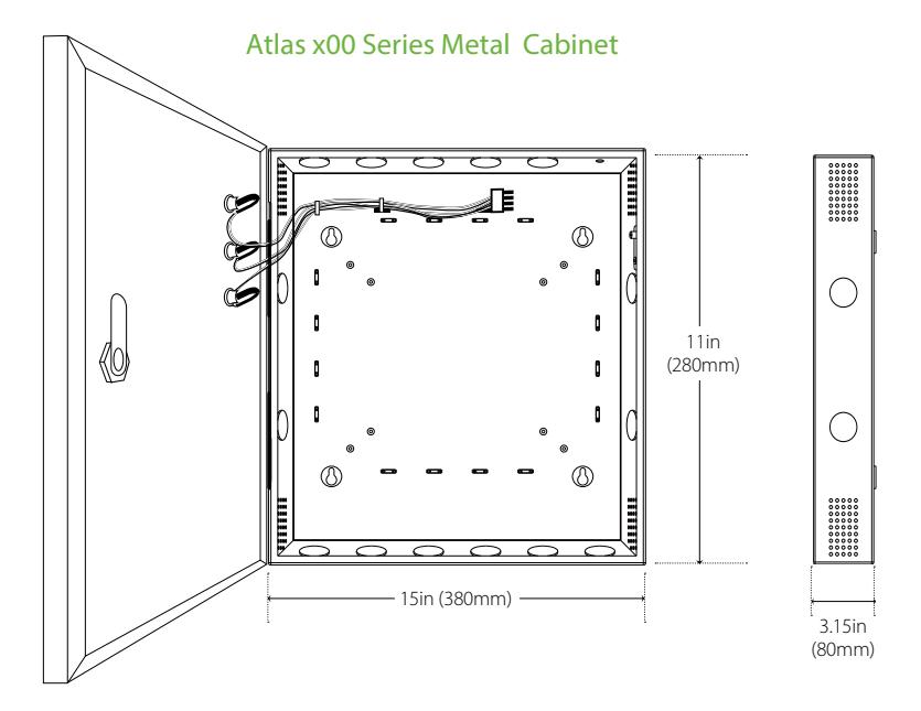
Figure 10
Installation of Panel & Cabinet
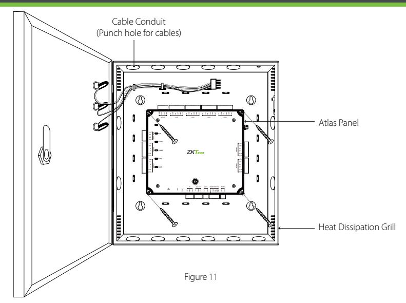
Step 1 Pass the cable through holes
Step 2 Mount the Metal Cabinet
Step 3 Fasten the Atlas Panel with four screws.
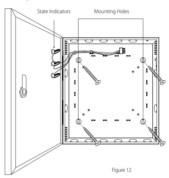
We recommend drilling the mounting plate screws into solid wood (i.e. stud/beam). If a stud/beam cannot be found, then use the supplied drywall plastic mollies (anchors).
Wiring Legend
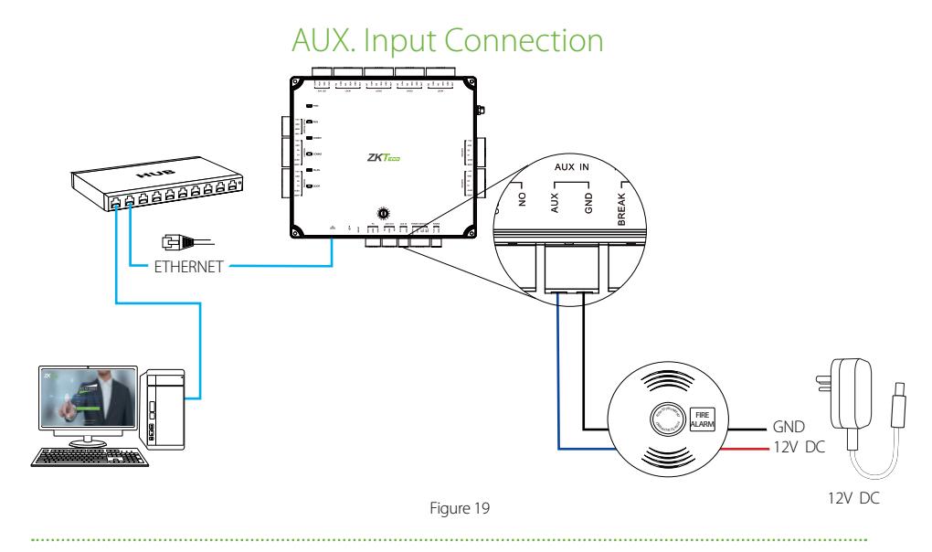
The auxiliary input may be connected to infrared motion sensors, fire alarms, or smoke detectors. The auxiliary output may be connected to alarms, cameras or door bells, etc.
Power Wiring Diagram
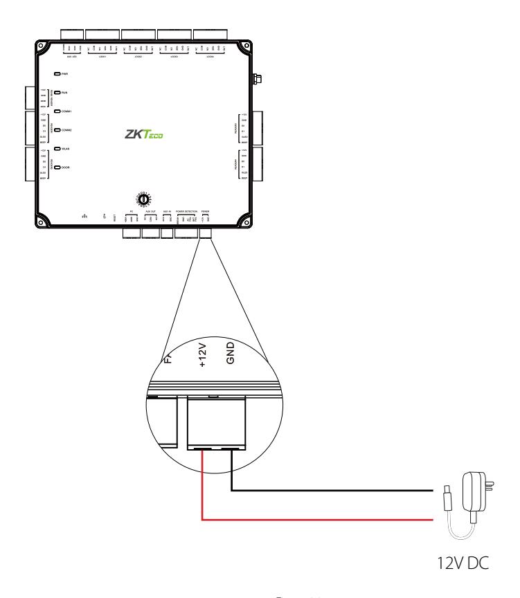
Figure 14
Wiegand Connection
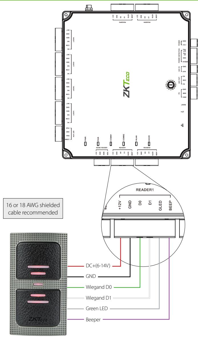
Wiegand Card Reader
Figure 15
OSDP Connection
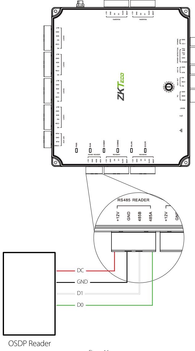
Figure 16
REX Connections
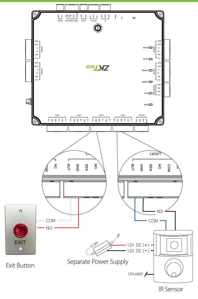
Figure 17
Lock Connection
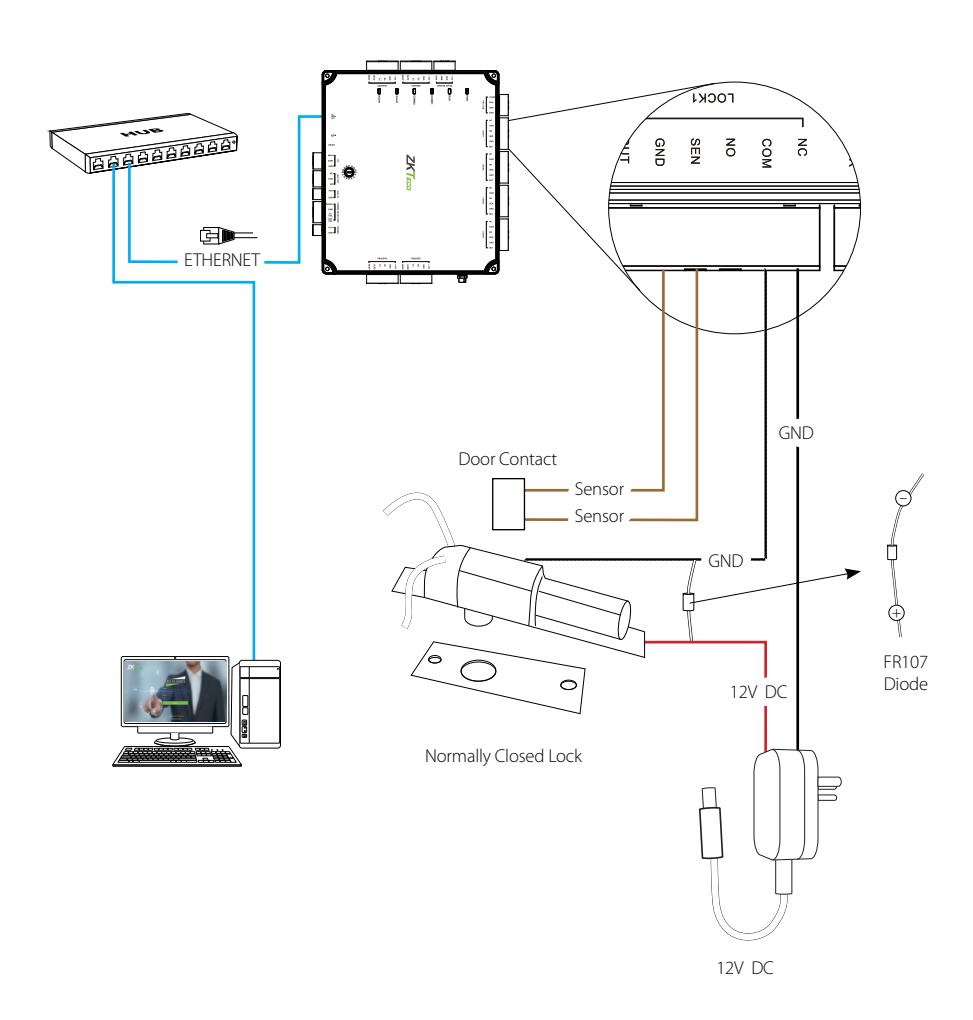
Figure 18
AUX. I/O Connection
AUX. Output Connection
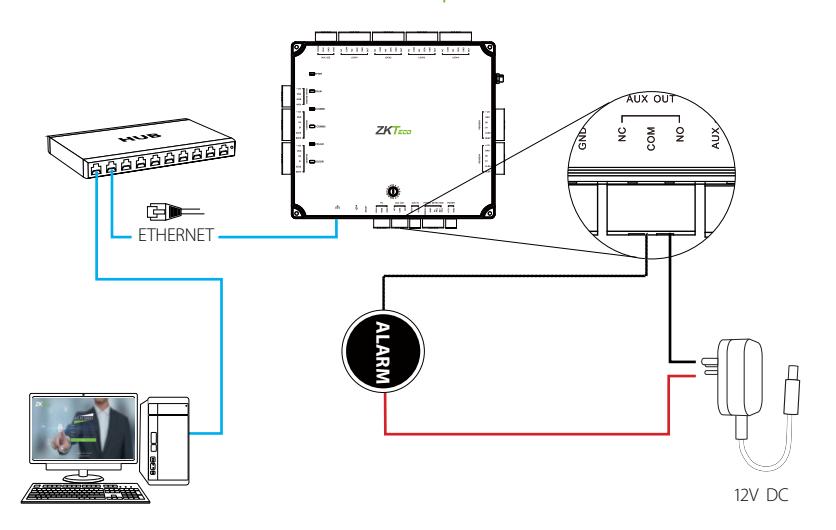
Figure 20
Ethernet Connection
LAN Connection
Important Notes:
- 1. Both 10Base-T and 100Base-T are supported.
- 2. This cable distance must be less than 330 ft. (100m).
- 3. For cable length of more than 330 ft. (100m). use HUB to amplify the signal.
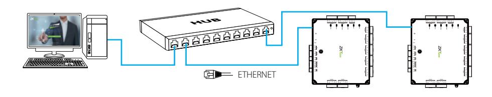
CAT5e or CAT6 ethernet cable recommended
Figure 21
Direct Connection
To connect Atlas-400 with a PC directly, connect both devices with a straight network cable. As the Atlas-400 supports auto MDI/MDIX, it is not necessary to use a crossover type cable.
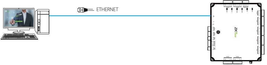
Figure 22
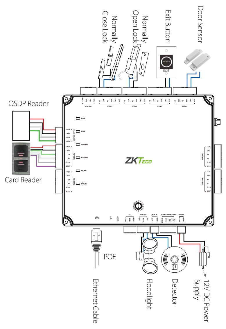
Installation Diagram
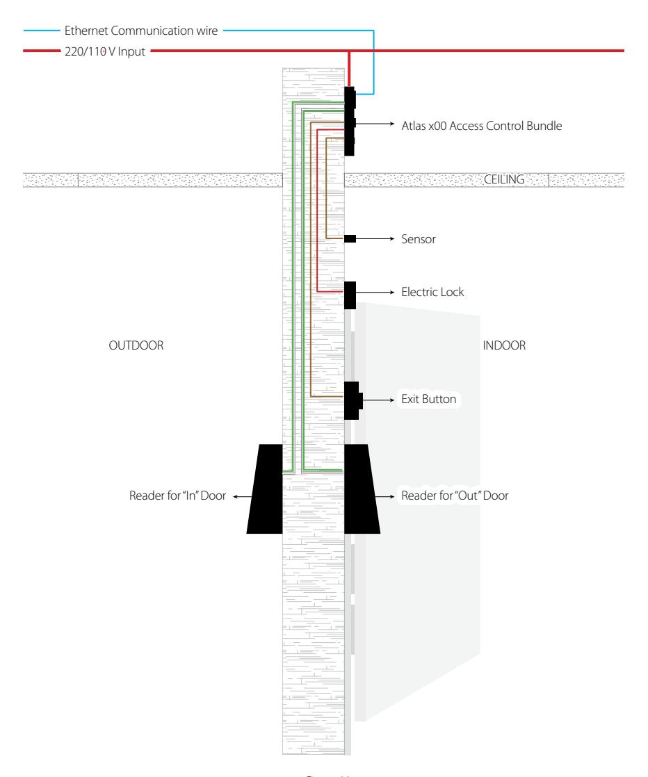
Figure 23
Troubleshooting
-
1.
How do I connect two-way doors?
- › Connect "Out" door readers as needed, in pairs with "In" door readers according to the following table.
| Model | "In" Reader | Pairs with "Out" Reader |
|---|---|---|
| 1-door | 1 | 2 |
| 1 | 3 | |
| 2-door | 2 | 4 |
| 4-door | 1 | 5 (RS485 connection) |
| 2 | 6 (RS485 connection) | |
| 3 | 7 (RS485 connection) | |
| 4 | 8 (RS485 connection) |
- › Connect door locks and sensors to the port for their "In" door.
- › See "Initial Controller Setup" in the "Programming Guide" for configuration instructions and additional options.
-
2.
What does it mean when I get "Access Denied (Unknown Format)?"
- › Your D0 and D1 wiring might be reversed.
- › The type of card you swiped might not be recognized. See "Add a User and Test Access" in the "Programming Guide."
-
3.
How do I connect a third party reader or a stand-alone reader to an Atlas x00 panel?
- › Connect the wiegand output to the WD0 and WD1 of the stand-alone readers on the panel's reader port.
Note: The board can only supply 12 V DC, 300mA power so an external power supply may be required.
-
4.
What kind of wire is recommended for the panel?
- › 16 or 18 AWG twisted shielded wire is recommended.
-
5.
What is the default IP of the panel?
- › 169.254.202.242 This is a "link local" IP address. See "Initial Controller Setup" in the "Programming Guide" for link local usage.
-
6.
How long is the device under warranty?
- › 2 Years from original purchase date, replacement/repair of hardware under ZK standard warranty requires an evaluation of the failed system by a ZK Technical Support specialist, and the issuance of a Technical Support RMA number.
Electrical Specifications
|
M
in im um |
Ty
pi ca l |
M
ax im um |
Notes | |
|---|---|---|---|---|
|
Working
power supply |
||||
| Voltage (V) | 9.6 | 12 | 14.4 |
Use regulated DC power
adaptor only |
| Current (A) | 2 | |||
|
Electronic
lock relay output |
||||
| Switching voltage (V) | 12V | 30V |
Use regulated DC power
adaptor only |
|
| Switching Current (A) | 2 | 3 | ||
| Auxiliary relay output | ||||
| Switching voltage(V) | 12V | 30V |
Use regulated DC power
adaptor only |
|
| Switching Current (A) | 1.25 | 1.5 | ||
|
Switch
Aux . input |
||||
| VIH (V) | TBD | 30V | ||
| VIL (V) | TBD | |||
| Pull-up resistance (Ω) | 4.7k |
The input ports are pulled
up with 4.7k resistors |
||
| WIEGAND Input | ||||
| Voltage (V) | 10.8 | 12 | 13.5 | |
| Current (mA) | 500 | |||
|
ZK Electronic
lock |
||||
| Voltage (V) | 10.8 | 12 | 13.2 | |
| Current (mA) | 500 |
Specifications
| Communication | TCP/IP, OSDP | |||
| Power Supply | 12V DC, 3A | |||
| Users Capacity | 5,000 | |||
| Event Database Capacity | 10,000 transactions, plus unlimited archive downloads | |||
| LED Indicator | Indicator for communication, power, status and prox card | |||
| Environment | 32-113 °F (0-45°C) | |||
| Operating Humidity | 20% to 80% | |||
| Number of doors controlled | Four Door (four door one way and two door two way) | |||
| Number of readers supported | Up to 4 Wiegand - 8 OSDP | |||
| 125kHz and 13.56MHz Wiegand readers, | ||||
| Types of readers supported | OSDP, others upon request | |||
| Number of Inputs | 9 (4 Exit Device, 4 Door Status, 1 AUX) | |||
| Number of Outputs | 5 (4- Form C relay for lock and 1- Form C relay for AUX output) | |||
| Weight | Atlas-100: 9lbs (3.8kg); Atlas-200/400: 10lbs (4kg) | |||
| Enclosure | Metal Cabinet | |||
| Mounting | Wall Mount | |||
| Dimensions (Bundle Only) | 14in. X 2.5in. X 12in. 380mm(L) X 80mm(W) X 280mm(H) | |||
| Dimensions (Board Only) | Atlas-100: 6.3in. X 4.17in. (160mm X 140mm) | |||
| Atlas-200/400: 7.75in. X 6.73in. (197mm X 171mm) | ||||
| CPU | 32 bit 1.2GHz | |||
| RAM | 256MB | |||
| Flash | 1GB | |||
| Certified | ||||
Atlas Series Web Management Application

Programming Guide
| Introduction23 | |
|---|---|
| Understanding the Atlas Series Network24 | |
| Initial Controller Setup25 | |
| Connect the Controller to the Network31 | |
| Complete the Configuration32 | |
| Add a User and Test Access36 | |
| Add Secondary Controllers38 | |
| Mobile App39 | |
| Special Considerations for Complex Networks43 | |
| Where to Go Next43 |
Introduction
Requirements
- 1. Obtain an available static IP address and configuration from the network administrator.
- 2. (Optional) Obtain a signed HTTPS certificate. This provides some additional security and avoids web browser warning messages. Supported certificate formats are PEM or PFX. See "Complete the Configuration," below.
- 3. Find out whether using network time protocol (NTP) to automatically update the controller clock over the Internet is possible and acceptable, as well as whether non-standard time servers are used (such as corporate time servers). With a typical small network, it is safe to assume NTP will work with default Atlas Series settings.
Procedure
- 1. Understand how an Atlas Series system networks together by reading the brief section, "Understanding the Atlas Series Network".
- 2. Connect a computer directly to a controller and run the initial configuration program. This step must be completed before the controller will operate on the network.
- 3. Connect the controller to the local network.
- 4. Log in to the controller with a web browser and complete essential configuration.
- 5. Add a user and test door access.
- 6. Add any secondary controllers you are installing.
Help
This guide refers you to online help topics for more detailed information. The help is available once you have connected the first controller and logged in to the Web Management Application. Open it by selecting "Help" from the menu in the upper right corner.
Expected Browser Warnings
Your browser will display an insecure site warning each time you log in to the Web Management Application. The exact text of the warning, and the way to resolve it, varies among browser applications. You can prevent this warning by installing a signed HTTPS certificate when directed, below.
Understanding the Atlas Series Network
All Atlas Series systems have a single "primary" controller. Many "secondary" controllers may be added to support additional doors. All secondary controllers maintain a connection to the primary, and the primary provides all data and configuration the secondaries need to operate.
The primary controller provides a Web Management Application you can log into from a web browser. This application on the primary controller is where you will manage all configuration for the entire system.
Important: The primary controller must support biometrics if any biometric controller will be used in the system.
Network Considerations
Ideally, all controllers should be networked on the same subnet. If you have a simple home or small office network, this will almost always be the case. For more complex networks, be sure to review the "Special Considerations" discussed at the end of this document before proceeding.
Connecting
- 1. Connect the controller to DC power.
- 2. Connect an ethernet cable directly from your computer to the controller.
- 3. If your computer is set to use a static IP address, you will need to temporarily change it to one in the range 169.254.202.xxx, or to DHCP. If you normally use DHCP, skip this step. If you do not know, try assuming you use DHCP, which is common.
- 4. Open a web browser and enter the default controller address: 169.254.202.242. You should get an insecure site warning from the browser (see above). After resolving the warning, you will be directed to the Web Management Application login screen. Note that it might take a minute for the connection to become available.
Trouble Connecting: If at any point you find you cannot connect to the controller at the default IP address, or the address you configure, below, you can try a hard network reset. Find the small opening on the controller labeled "Reset." Insert a paperclip to depress the button for 5-10 seconds. The controller address will revert to the default, 169.254.202.242, until rebooted, reset, or the configuration is modified.
Running the Setup Wizard
Log in using the default administrator account:
- • User name: admin
- • Password: admin
You will be directed to the Setup Wizard, where you will enter information required for the controller to operate.
Page 1: Language
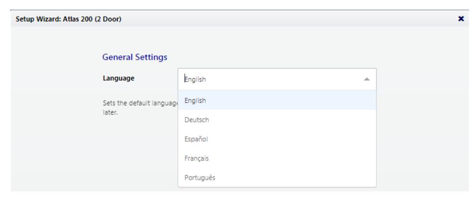
Choose a language. Your choice will be used for this wizard. It will also become the default language of the Web Management Application. This can be changed later in the hardware configuration of the primary controller.
Note: For secondary controllers, Language does not affect the Web Management Application. It does set the language of the simplified management application on this controller, and can be changed later in the configuration of this controller.
Page 2: Function
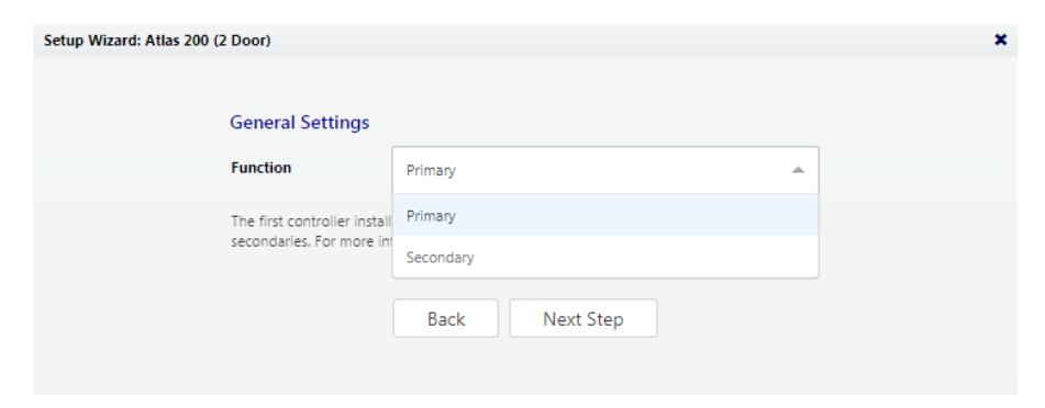
Choose whether this controller will be a "Primary" or a "Secondary". Make sure you understand the Atlas Series network, discussed above. The first controller installed should be a primary, and all others should be secondaries.
Page 3: Primary Controller Name (primaries only)
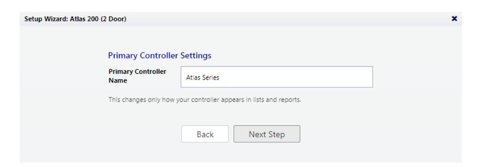
The name of the controller will be used for display in the Web Management Application and in reports.
Note: secondary controllers are named when they are connected to the system in the Web Management Application.
Page 4: Configuration (primaries only)
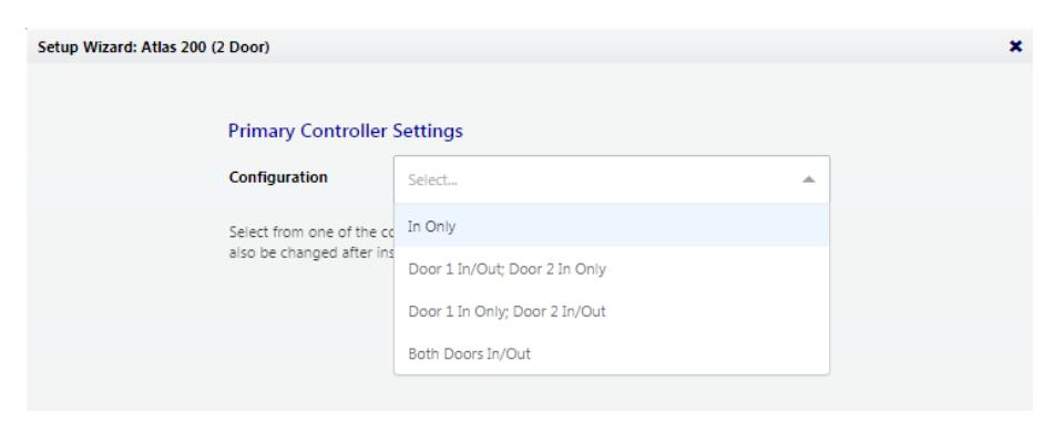
This determines what your controller will be used for: controlling door entry, perhaps door exit, or as special purpose readers.
Note: Secondary controllers are configured when they are connected to the system.
Configuration options available depend on the controller model. Each option will involve one or more of the following possibilities. Each possibility determines the function of the card, PIN, or biometric readers connected to the controller. The configuration can be modified during "Complete the Configuration," below.
In Only - This the most common configuration, where a reader is used to gain entry, but no credentials are required to exit (although an exit button may be configured for opening the door from the inside).
All controllers will have at least one "In" reader. It cannot be configured for another purpose, though you may choose not to use it.
In/Out - The physical door will have a reader both inside and outside. Authorization is required to pass either direction.
- + Muster Point The second reader will serve as a muster point, where users can register that they have reached a safe location.
- + Card Enrollment Point The second reader will be used to easily enter card numbers when adding users.
Page 5: Time Zone (primaries only)
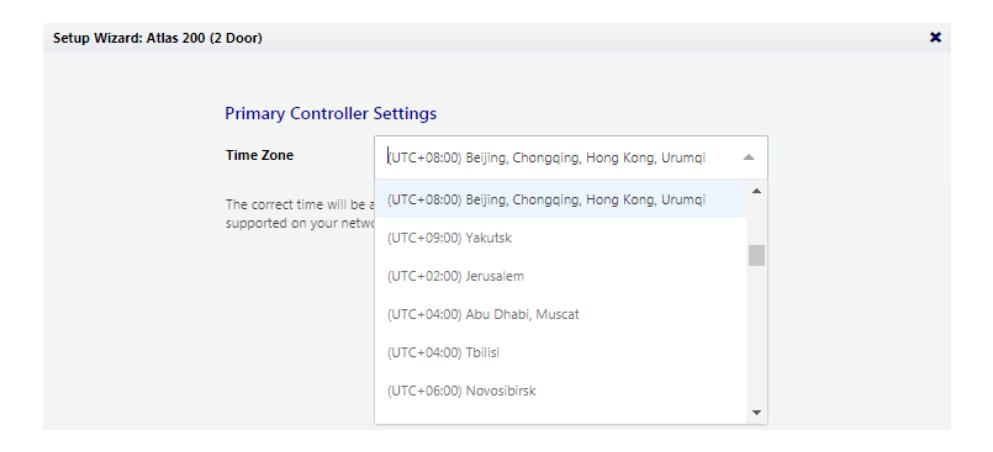
Select your time zone. In most cases you will never need to set the actual time; the controller will get the time from the internet using a technology called NTP. Other situations are discussed, below, under "Complete the Configuration."
Note: Secondary controllers get their time and time zone from the primary controller.
Page 6: Password (primaries only)
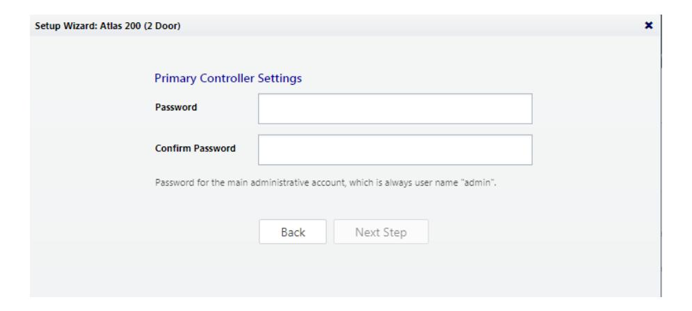
Enter a strong password for the primary administrator account. The user name for this account is "admin" and cannot be changed.
Page 7: Network Interface Settings
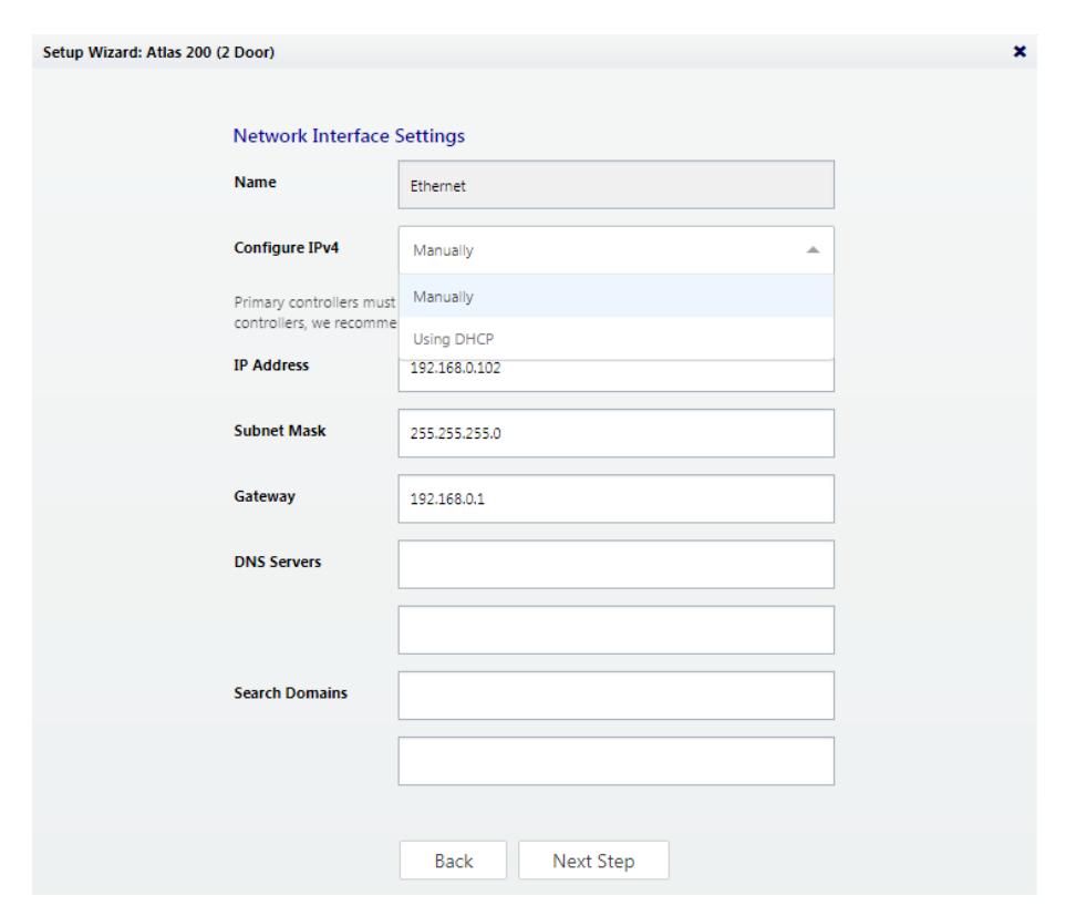
The important choice here is "Configure IPv4."
A primary controller must have a static IP address. This is because secondary controllers need to know how to find the primary on the network. Additionally, the users need a consistent address to log in to the Web Management Application.
To assign a static IP address, choose "Manually" and enter the IP address and configuration specified by the network administrator.
"Using DHCP" is probably the right choice for secondary controllers, unless you have a complicated network discussed below under "Special Considerations for Complex Networks."
Wireless Networking: If your controller model supports WiFi, you still need to set up a wired connection, here. You can add your wireless connection once you are logged in to the Web Management Application. See the online help topic, "Administration: Network".
Page 8: Review
All your entries are displayed for review. Click either "Back" or "Complete Setup." After completing setup, you may disconnect the direct ethernet cable.
Connect the Controller to the Network
When you "Complete Setup," the controller will reboot itself automatically. If it is already installed, then simply reconnect it's ethernet port to the local area network.
Otherwise, disconnect the controller and complete the physical installation. Connect it to the local area network via ethernet.
Open a web browser and enter the IP address you specified in Network Interface Settings during initial setup. This will direct you to the login screen of the Web Management Application. Enter "admin" as the user, and use the password you set during initial configuration. The application Dashboard will appear. Expect to see green status, indicating everything has completed correctly to this point.
Review Time Settings (optional)
By default, the primary controller will use network time protocol (NTP) to automatically update the controller clock over the internet. This might not work due to local policies or because your controller does not have internet access.
If you need to change this configuration go to "Admin Date and Time."
- • To disable NTP, uncheck "Update Date and Time Automatically." When this box is not checked, you can manually set the time by checking "Set Server Time to Current Browser Time" and clicking Save .
- • If you wish to use NTP, but with customized NTP servers, there is space to enter those server addresses. The default servers are: "0.pool.ntp.org," "1.pool. ntp.org," "1.pool.ntp.org," and "3.pool.ntp.org."
- • You can also turn off the use of Daylight Savings Time.
Registration (optional)
Registration is required if you ever need to reset your system password, and optionally allows ZKTeco to contact you about software updates and other information. Follow these steps to register for the first time or to update your registration information.
-
1.
Registration can be started in two ways:
- • When you log in the first time, click Register Now in the "Register Your Product" pop-up window, or
- • Select "Menu About," and click the Register button. (If you have previously registered, the link is "Update Registration.")
- 2. Click New Registration button in the next pop-up window. (If you have previously registered, the button is "View/Update Registration.")
- 3. Fill in the registration information. Asterisks indicate required information. The email address you enter must be able to receive your registration information.
-
4.
Submit your registration automatically or by email.
- a. For automatic registration, click Submit Online button. You will see a progress window followed by a success message.
-
b. For email registration:
- i. Click Offline Registration button. Read the instructions in the following window.
- ii. Click Download registration file link, and save the registration data file to your computer.
- iii. Create and send an email message by clicking the email link or entering it in your email program. Your email must contain the registration data file as an attachment, with its original name. The subject and text of the email do not matter.
You will receive a registration confirmation file by reply email. When you do,
- 1. Open the email and save the attachment to your computer.
- 2. Click Upload Confirmation button. (If you have already exited from registration, then return to this option by selecting "Menu About" and clicking the Register button.)
- 3. Find and open the registration confirmation file you saved.
You should see a "Registration successful" message window.
Fine Tune Hardware Configuration
Configuration is discussed in detail in the online help topic, "Configuration: Hardware." Topics mentioned below are found within that section.
Go to "Config Hardware." The list on the left shows all controllers. (At this point, you should see one, the primary.) Each controller has an "I/O" sub-controller listed beneath it. The controller item manages general controller configuration, while the sub-controller manages detailed configuration of the readers, inputs, and outputs.
Click the controller and review the configuration. Note under "Managed Doors" that doors were automatically created to match the controller configuration you chose earlier. Every reader is represented as a door, whether its function is in, out, card enrollment point, or muster point.You might need to:
-
• Add more readers using the "Modify" button on the menu bar. Details about this operation are in the topic, "Modifying Controller Configuration". The Modify options are:
- o "Change to In/Out"
- o "Add Muster Point"
- o "Add Card Enrollment Point"
- o "Remove Secondary, Muster, or Card Enrollment Point"
- • Change the default connection type for readers (Wiegand, OSDP, or ZKTeco RS-485). These settings are on the sub-controller, and are detailed in the topic, "Hardware Properties". The defaults vary by model and are listed in the topic, "Models and Configurations". Note that OSDP and ZKTeco RS-485 cannot be combined on the single RS-485 port.
- • Change the connection properties of inputs and outputs and configure optional functionality of auxiliary inputs and outputs. These settings are on the sub-controller, and are detailed in the topic, "Hardware Properties".
Configure Doors
Go to "Config Doors". Every reader is represented as a door, whether its function is in, out, card enrollment point, or muster point.
For In and Out doors, change the "Default Mode" to set the door's normal locking state.
For In doors, review the lock timings and behaviors under "Operation".
Card enrollment and muster doors usually need little configuration.
See the online help topic, "Configuration: Doors", for more advanced configuration, such as
- • changing door mode on a schedule,
- • anti-passback, and
- • applying the same settings to multiple doors
Install a Fingerprint Enrollment Reader (optional)
If you are using biometric readers, a ZKTeco USB fingerprint enrollment reader must be installed at any computer where fingerprints will be enrolled.
- 1. Plug the device into any USB port.
- 2. Install the Fingerprint Driver software (available on the Downloads page at ZKTecoUSA.com)
Install a Signed Certificate (optional)
To provide extra security for the controller, and to avoid browser warnings when logging in, you might wish to install a signed HTTPS security certificate. For more information on what this means, and to get such a certificate, talk to your IT department.
Even if you do not install a signed certificate, all communications will still be encrypted.
To install a certificate:
- 1. Obtain a certificate file in .PEM or .PFX format and copy it to your computer.
- 2. Select "Admin Web Server Settings."
- 3. Click Upload Certificate .
- 4. Complete the prompts to select and upload the certificate file.
Add a User and Test Access
- 1. Go to "Access Users."
- 2. Click Create on the menu bar.
-
3.
Enter the following minimum required information:
- • First Name
- • Last Name
- • (To test cards) Scroll down to "Cards," click the Add button, then enter the number of a card.
- • (To test PINs) Scroll down to "PIN" and either enter a 4 digit number or use the "Create New" button to generate a random value.
- 4. Scroll down to "Door Access." Click the Add button and select 1 or more doors on the following screen.
- 5. Click Save on the menu bar.
The card, PIN, and fingerprint you entered should now work to grant access at the specified doors, assuming you chose a compatible "Default Mode" during "Configure Doors."
To test access, you will (1) create an access level, (2) create a user, (3) give the user card, PIN, and/or biometric credentials, and (4) assign the access level to the user.
First:
- 1. Go to "Access Access Levels."
- 2. Click "Create" on the menu bar.
- 3. Enter a "Name" for the access level.
- 4. Click the "Add" button.
- 5. In the pop-up window, select one or more doors that this access level will provide access to, and click "OK."
- 6. On the "Access Levels" screen, notice that each door has been added to the list with a schedule during which access will be granted. The default schedule, "24/7," provides access at all times. Schedules are explained further in the online help.
- 7. Click "Save" on the menu bar.
Add a User and Test Access
Then:
- 1. Go to "Access Users."
- 2. Scroll down to "Access Levels." Click the Add button and select the access level you created, above.
- 3. Click Save on the menu bar.
The card, PIN, and fingerprint you entered should now work to grant access to the specified doors during the specified schedules, assuming you chose a compatible "Default Mode" during "Configure Doors."
Card formats that work out of the box are Wiegand (26, 34, 37, or 50 bits) and Corporate 1000 (35 bit). For other formats, see the online help topic, "Configuration: Card Formats."
More sophisticated ways to grant access to users are discussed in the online help under the main topic, "Access Control."
Card numbers can be more easily entered by using enrollment points. See the online help topic, "Features and Tasks: Card Enrollment Points."
The number of digits for PINs can be changed in "Admin System Settings."
Add Secondary Controllers
Step 1: Initial Setup
Follow the instructions under "Initial Controller Setup," above, for each controller. This will configure the controller for connection to the network.
Step 2: Add the Controller in the Web Management Application
Secondary controllers can be automatically found and added by the Web Management Application. This is called "Discovery."
There are two important qualifications about Discovery.
- • When using Discovery, you should connect and discover controllers one at a time. This is the only way you can differentiate them.
- • Discovery only works if all controllers are networked on the same subnet. If you have a simple network, this will almost always be true. In a larger corporate environment, you might need to add secondary controllers manually. See "Special Considerations…," below.
To discover secondary controllers:
- 1. Log in to the Web Management Application (on the primary controller).
- 2. Go to "Config Hardware."
- 3. Click Discover Controllers on the menu bar.
- 4. In a few moments, a form will display all controllers discovered.
-
5.
Click the link to add a controller. The create controller screen will appear.
- a. Select a "Configuration." (See "Initial Controller Setup", above.)
- b. Enter a "Name," and select "Custom Door Names" so you can name the doors.
- c. Leave all other settings as they are. These are the settings that were discovered.
- d. Click Save on the menu bar.
ZKTeco provides its "Atlas" mobile app in Apple's "App Store" and in "Google Play." You must authorize each mobile device before it can access your system. In the Web Management Application:
1. Go to "Admin Authorized Mobile Devices."
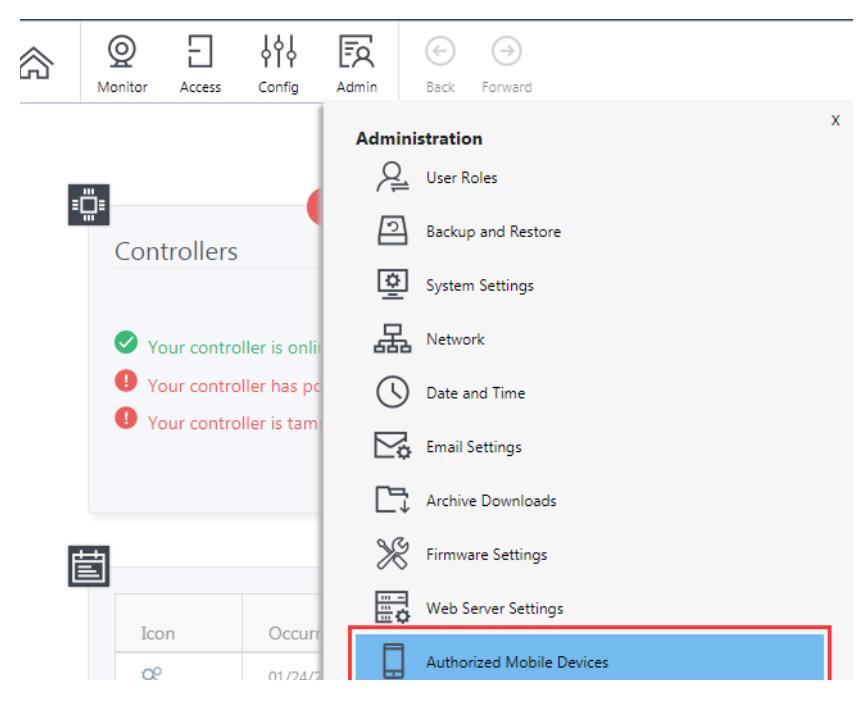
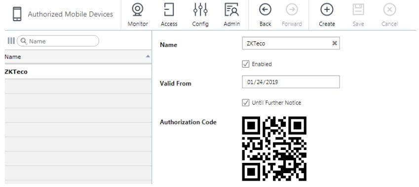
2. Create and Save an authorization.
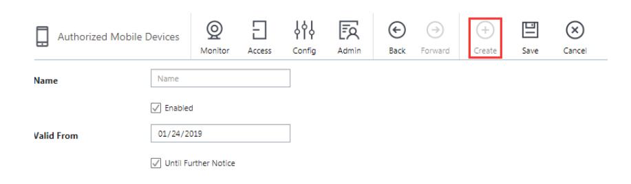
-
3.
A QR code image will be displayed in the "Authorization Code" field.
- • Leave this open for scanning, below, or
- • right click the image to save it. You can then email the image to the mobile device user.
On the mobile device:
- 1. Install and run the "Atlas" mobile app.
- 2. Press Scan QR Code .
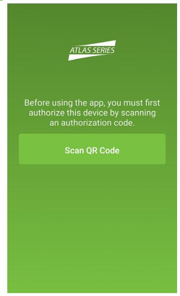
- 3. You might have to confirm that Atlas may use the camera.
- 4. The photo viewfinder will appear. Point the square scanning box at any copy of the authorization QR code. A picture will be taken automatically when a QR code is within the box, showing the message, "Authorization code successfully located."
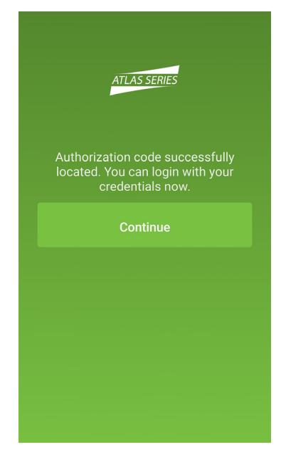
5. The "Sign In" screen is next. Enter the "Server Address" of the primary Atlas Series controller. Enter your Atlas Series "Username" and "Password." Press Sign In .
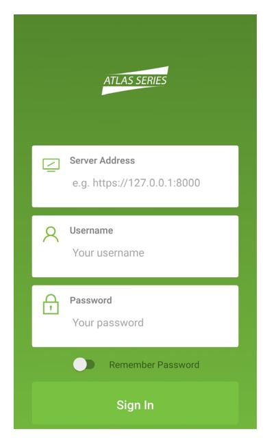
6. Once signed in you will see a list of everything you can do, including viewing alarms or status and initiating emergency lockdown.
Important: The mobile device must be connected by WiFi to the same local network as the Atlas Series controllers. To connect from a distance, your network administrator must in some way open access from the Internet (such as by using a NAT) and provide the necessary "Server Address."
Each authorization code can authorize only one mobile device. You may delete and add authorizations as needed to support several devices. The number of devices you can authorize is limited by your license.
Special Considerations for Complex Networks
If all Atlas Series controllers cannot be located on one network subnet, or if Discovery is blocked by network restrictions, observe the following.
- • There is no difference in the way you set up the primary controller.
- • During "Initial Controller Setup" of secondary controllers on other subnets, do not select DHCP as normally recommended. Assign these controllers static IP addresses.
- • Manually add these secondary controllers in the Web Management Application. Log in and read "Manually Adding Secondary Controllers" in the help topic, "Configuration: Hardware: Adding Controllers."
Where to Go Next
A complete user manual is available through the Management Application by selecting "Help" from the menu in the upper right corner.
The help's "Introduction" page will guide you to more information on operating the application, changing the configuration of controllers and doors, setting up door access, using emergency features, and more.