Z7870-72 & Z7880-Z7882 Mortise Lock Installation Instructions
Open the original PDF document
View PDF

801 Avenida Acaso, Camarillo, Ca. 93012 • (805) 494-0622 • www.sdcsecurity.com • E-mail: service@sdcsecurity.com
INSTALLATION INSTRUCTIONS Z7870/72 & Z7880/Z7882 MORTISE LOCK
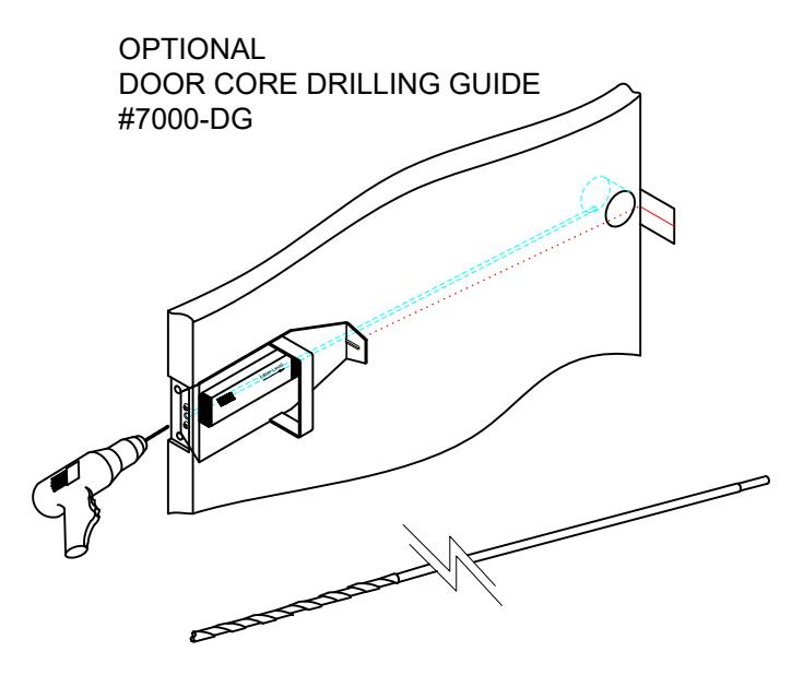
A. Door Preparation:
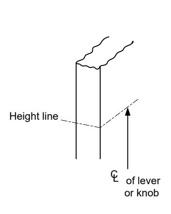
- 1. Measure desired height from finished floor, mark a horizontal line on door and door edge.
- 2. Align template on edge of door with applicable horizontal at height line. Check the chart for drilling trim holes on template and mark only holes for lock function being installed.
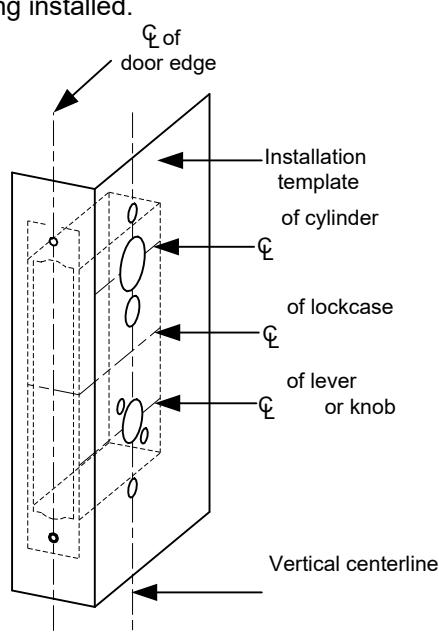
- 3. Mortise door edge according to measurements on installation template and drill proper holes for trim.
- 4. Recess for face plate, the dimension is: L 8-1/32" x W 1-5/16" x D 7/32".
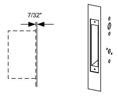
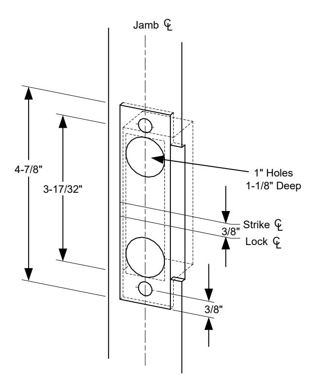
B. Strike Installation:
- 1. Align strike template on jamb. Be sure to keep 3/8" distance between lock centerline and strike centerline. Recess 5/32" for flush fit of strike and dust box.
- 2. Mortise jamb according to measurement of strike template. Then fit strike and dust box into frame and secure into place with supplied screws.
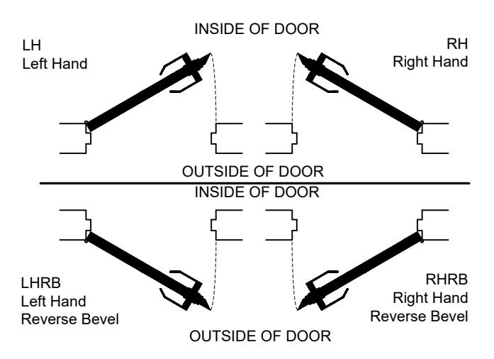
C. Install Lockcase
Make sure the lock hand matches the door hand, use the following diagram to determine the hand of door.
C Install Lockcase (Continued)
Instructions for changing lock hand:
REX option Locksets are factory set per handing and can't be changed in the field.
1. Change latchbolt handing
If the hand of the latchbolt doesn't match the door hand, remove the fixing screw and pull the latchbolt out from lock case. Turn the latchbolt 180 ° to change the handling. Position latchbolt back, into case and fasten it.
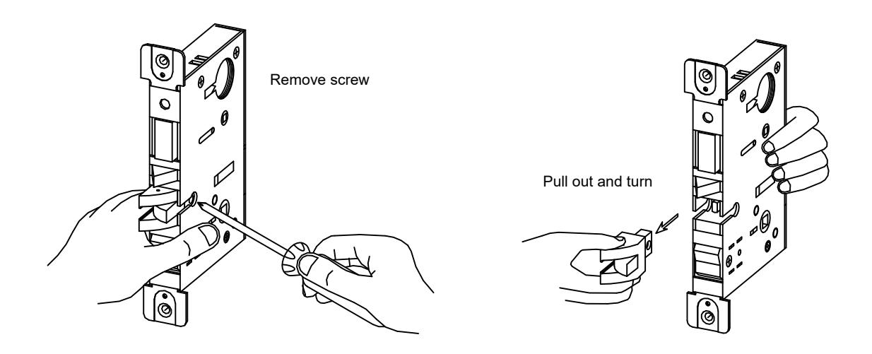
2. Change hand of lock
For RH and RHRB, the catch screw will be on the lock case side. For LH and LHRB, the catch screw will be on the lock cover side.
3. Connect wires as shown on the lock cover diagram. 4. Insert lockcase into mortise cut-out and fasten screws to door. C. Install Lockcase (Continued)
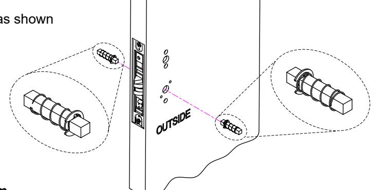
D. Install Spindles
1. Insert spindles as shown
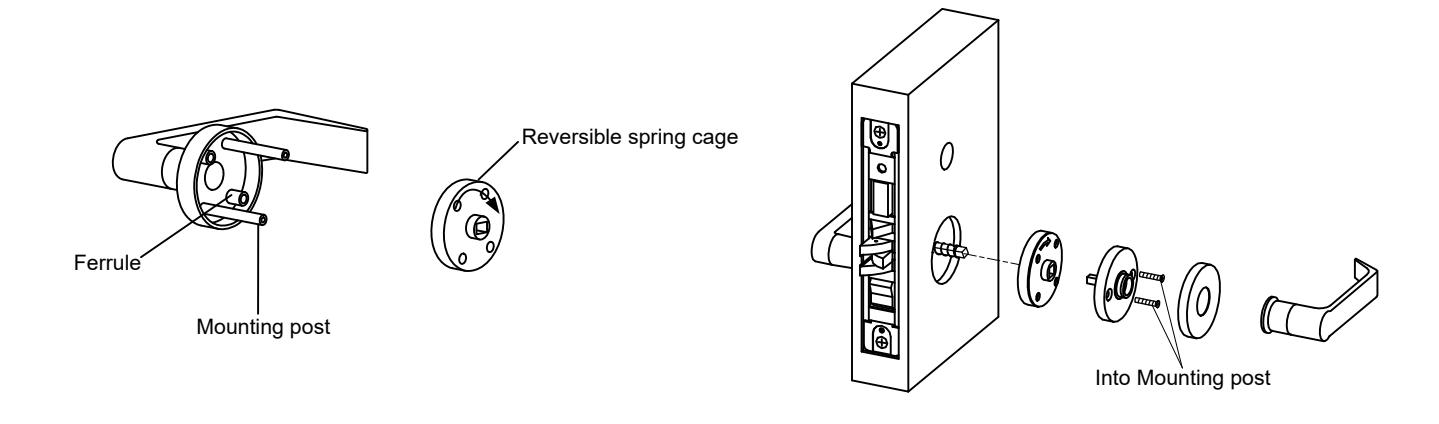
E. Install Lever trim
- 1. Place the reversible spring cage onto the ferrules with arrow pointing in direction of lever rotation.
- 2. Install outside trim with mounting posts through door and position lever onto the spindle.
- 3. Install inside spring cage onto the spindle with the arrow pointing in the direction of inside lever rotation.
- 4. Install inside mounting plate onto spindle. Tighten with provided screw.
- 5. Cap inside rose over mounting plate.
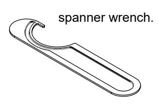
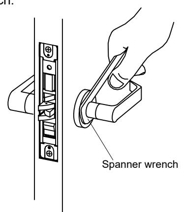
E. Install Lever trim (continued)
6. Screw inside lever into position and tighten lever collar with supplied spanner wrench.
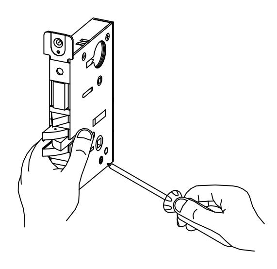
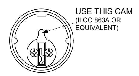
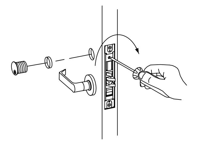
F. Install Cylinder and Armor Face Plate
- 1. Screw cylinder into threaded hole of lock case.
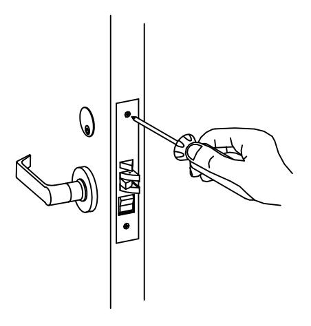
- 2. Tighten the setting screw against cylinder(s) by turning clockwise as shown.
- 3. Install face plate onto lock case front and fasten with supplied screws.
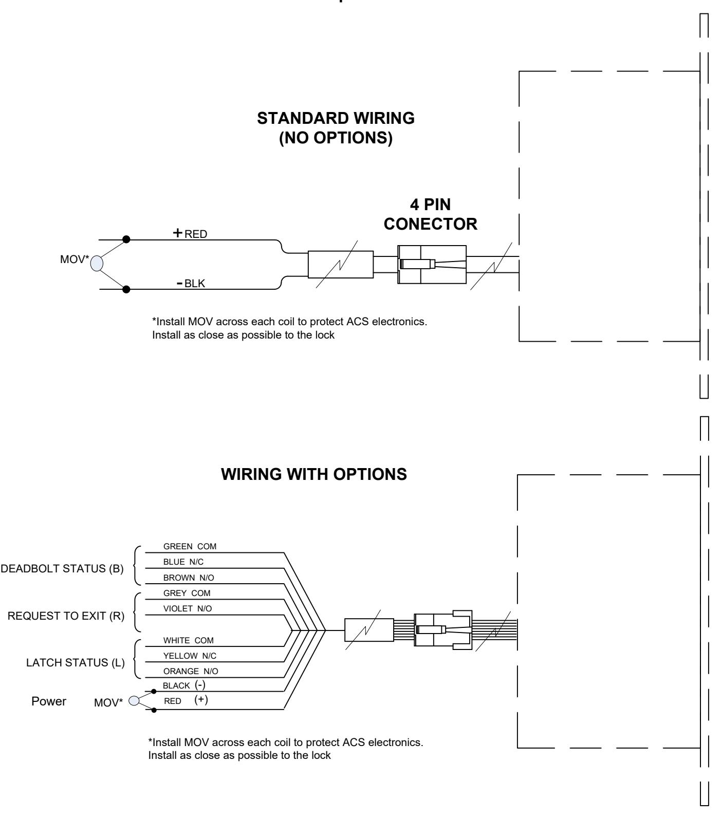
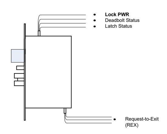
INSTALLATION WIRE DIAGRAM Model 7870/72 & 7880/82 Series
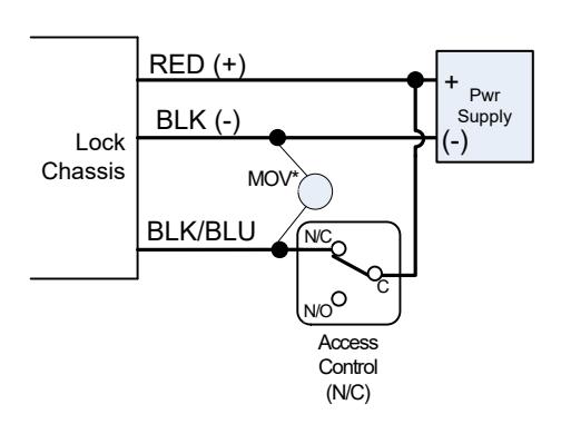
STANDARD WIRING 12 or 24VDC (Locks are voltage specific) 12VDC@.6AMP; 24VDC@.3AMP
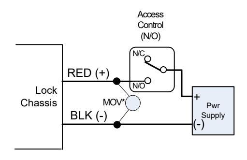
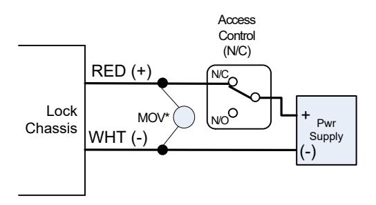
Z7880 (Failsafe) Lock Power (12VDC)
Access control does not engage the outside lever when the deadbolt is thrown. *Install MOV across coil to protect ACS electronics, as close as possible to the lock
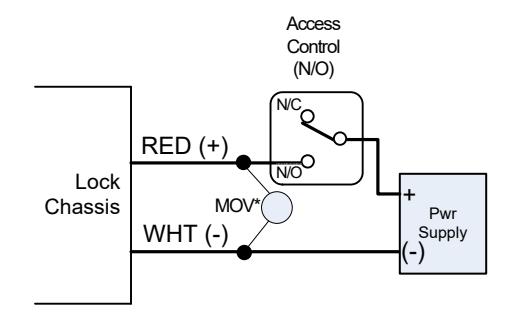
Z7880 (Failsafe) Lock Power (24VDC )
Access control does not engage the outside lever when the deadbolt is thrown. *Install MOV across coil to protect ACS electronics, as close as possible to the lock
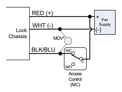
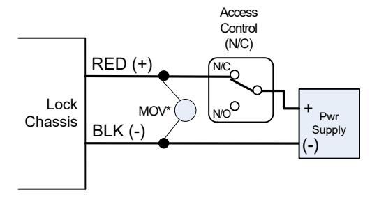
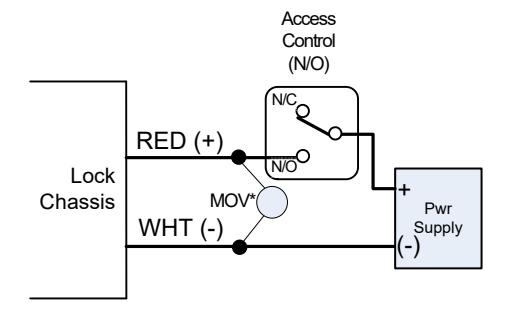
Z7882 (Failsecure) Lock Power (12VDC)
Access control does not engage the outside lever when the deadbolt is thrown. *Install MOV across coil to protect ACS electronics, as close as possible to the lock
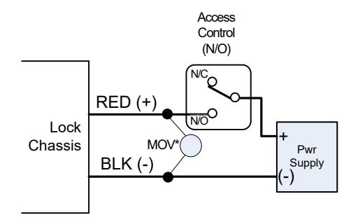
Z7882 (Failsecure) Lock Power (24VDC)
Access control does not engage the outside lever when the deadbolt is thrown. *Install MOV across coil to protect ACS electronics, as close as possible to the lock
Z7870 (Failsafe) Lock Power (12VDC)
Access control always engages outside lever. *Install MOV across coil to protect ACS electronics, as close as possible to the lock
Z7872 (Failsecure) Lock Power (12VDC)
Access control always engages outside lever. *Install MOV across coil to protect ACS electronics, as close as possible to the lock
Z7870 (Failsafe) Lock Power (24VDC)
Access control always engages outside lever. *Install MOV across coil to protect ACS electronics, as close as possible to the lock
Z7872 (Failsecure) Lock Power (24VDC)
Access control always engages outside lever. *Install MOV across coil to protect ACS electronics, as close as possible to the lock
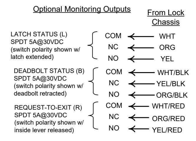
INSTALLATION WIRE DIAGRAM Models with optional connectors