Z7800 Electrified Mortise Lock Installation Instructions
Open the original PDF document
View PDF[t] 800.413.8783 8 805.494.0622 8 E-mail: service@sdcsecurity.com 8 801 Avenida Acaso, Camarillo, CA 93012 9 PO Box 3670, Camarillo, CA 93011
INSTALLATION INSTRUCTIONS
Z7800 SERIES MORTISE LOCK
A. Door Preparation:
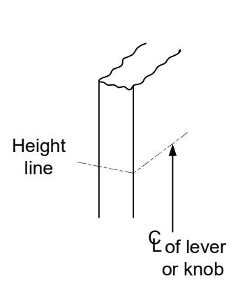
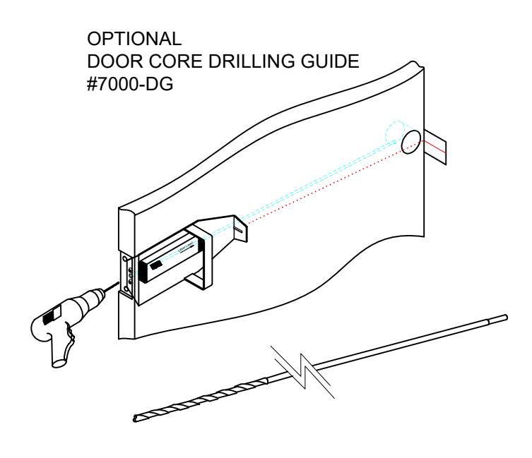
- 1. Measure desired height from finished floor, mark a horizontal line on door and door edge.
- 2. Align template on edge of door with applicable horizontal at height line. Check the chart for drilling trim holes on template and mark only holes for lock function being installed.
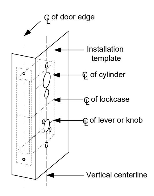
- 3. Mortise door edge according to measurements on installation template and drill proper holes for trim.
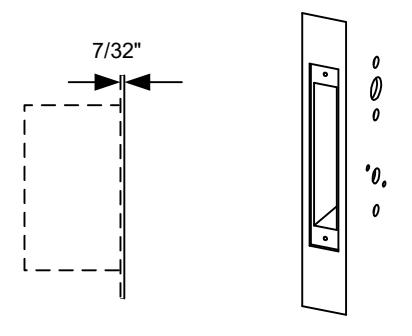
- 4. Recess for face plate, the dimension is: L 8-1/32" x W 1-5/16" x D 7/32".

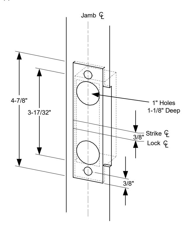
B. Strike Installation:
- 1. Align strike template on jamb. Be sure to keep 3/8" distance between lock centerline and strike centerline. Recess 5/32" for flush fit of strike and dust box.
- Mortise jamb according to measurement of strike template. Then fit strike and dust box into frame and secure into place with supplied screws.
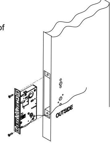
C. Install Lockcase
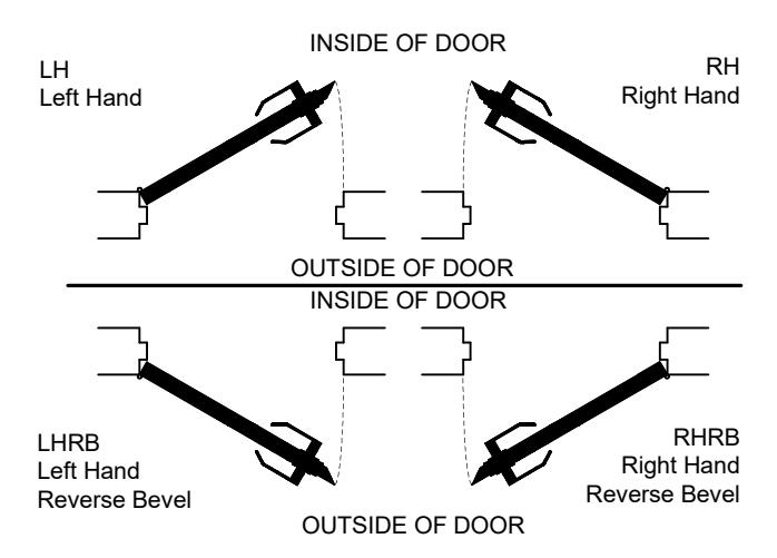
Make sure the lock hand matches the door hand, use the following diagram to determine the hand of door.

C. Install Lockcase (Continued)
Instructions for changing lock hand:
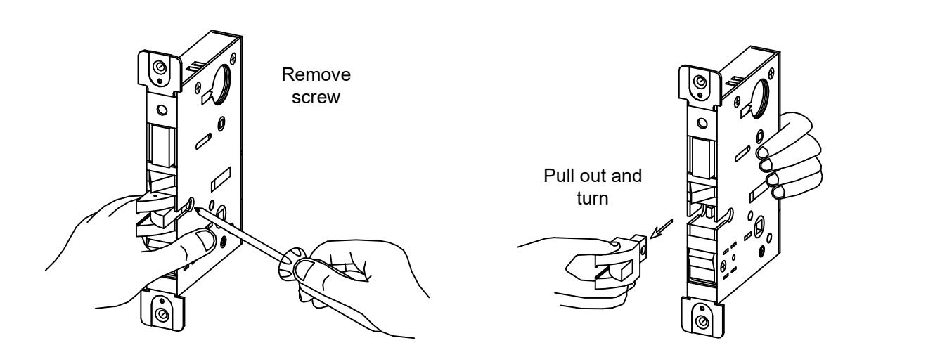
1. Change latchbolt handing
If the hand of the latchbolt doesn't match the door hand, remove the fixing screw and pull the latchbolt out from lock case. Turn the latchbolt 180 ° to change the handling. Position latchbolt back, into case and fasten it.
2. Change hand of lock
For RH and RHRB, the catch screw will be on the lock case side. For LH and LHRB, the catch screw will be on the lock cover side.
C. Install Lockcase (Continued)
- 3. Connect wires as shown on the lock cover diagram (Or refer to page 6 of instructions.)
- 4. Insert lockcase into mortise cut-out and fasten screws to door.
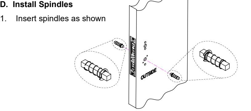
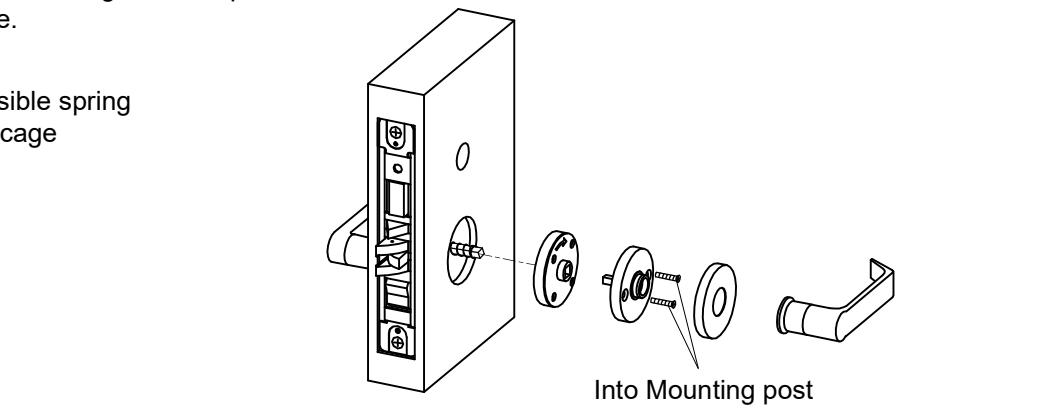
E. Install lever trim
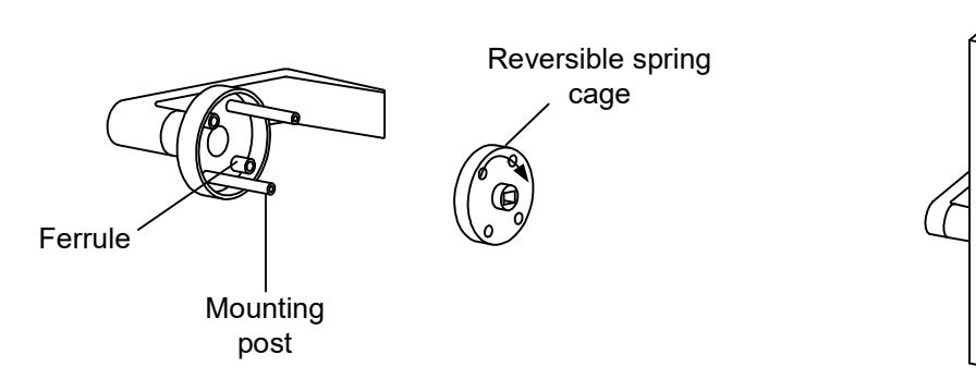
- 1. Place the reversible spring cage onto the ferrules with arrow pointing in direction of lever rotation.
- 2. Install outside trim with mounting posts through door and position lever onto the spindle.
- 3. Install inside spring cage onto the spindle with the arrow pointing in the direction of inside lever rotation.
-
4. Install inside mounting plate onto spindle. Tighten with provided screw.
- 5. Cap inside rose over mounting plate.
6. Screw inside lever into position and tighten lever collar with supplied spanner wrench.


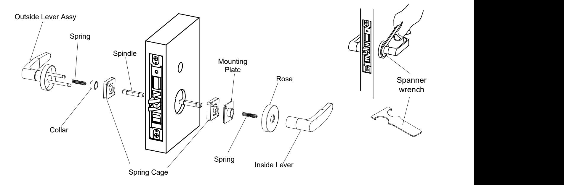
E. Install for 07 lever trim
- 1. Place the spring, collar and then reversible spring cage onto the outside lever assembly with arrows pointing in direction of lever rotation. Insert spindle into hub of lock case.
- 2. Install outside lever assembly with mounting posts through door and position lever assembly onto the spindle.
- 3. Install inside spring cage onto the spindle with the arrows pointing in the direction of inside lever rotation.
- 4. Install inside mounting plate over spindle and onto the mounting posts of outside assembly. Tighten with provided screws. 5. Cap inside rose over mounting plate and insert second spring.
- 6. Screw inside lever into position and tighten lever collar with the supplied spanner wrench.
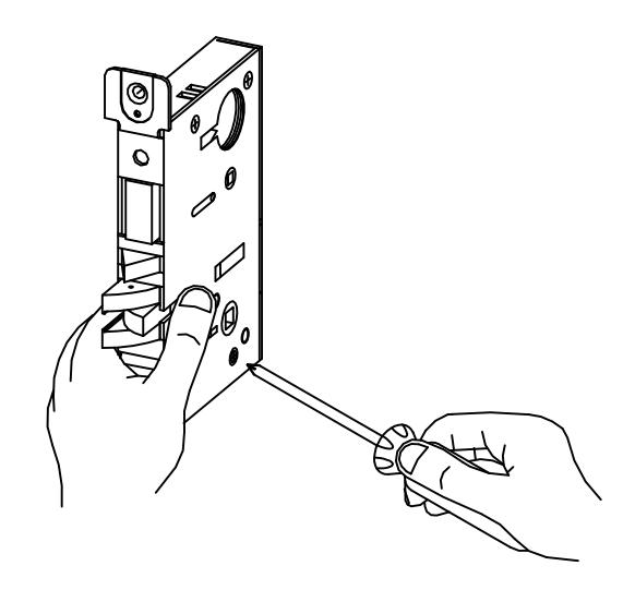
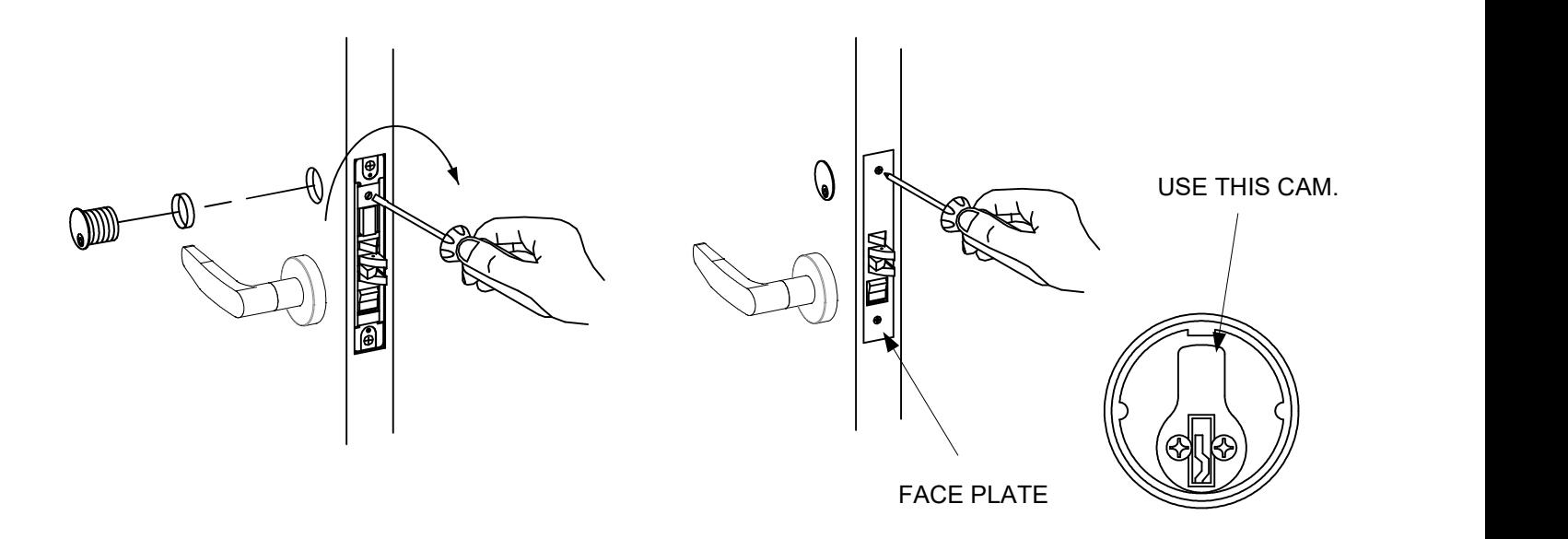
F. Install Cylinder and Armor Face Plate
- 1. Screw cylinder into threaded hole of the lock case.
- 2. Tighten the set screw against cylinder(s) by turning clockwise as shown.
- 3. Install face plate onto the lock case and fasten with supplied screw.

Install as close as possible to the lock
[t] 800.413.8783 805.494.0622 E-mail: service@sdcsecurity.com 801 Avenida Acaso, Camarillo, CA 93012 PO Box 3670, Camarillo, CA 93011
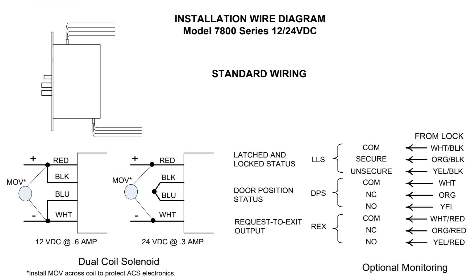
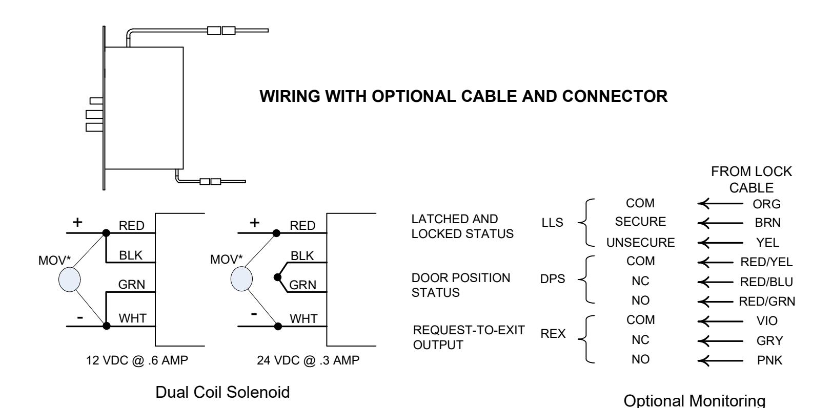
*Install MOV across each coil to protect ACS electronics.
Install as close as possible to the lock

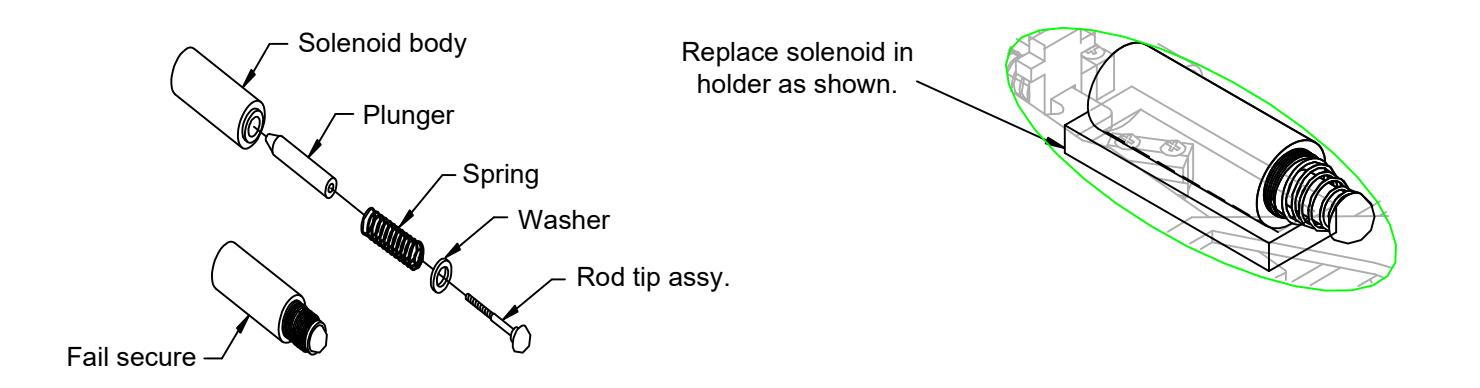
FAIL SAFE/FAIL SECURE CONVERSION Procedure To Change SDC Fail Safe Solenoid To Fail Secure
Fail Safe Assembly
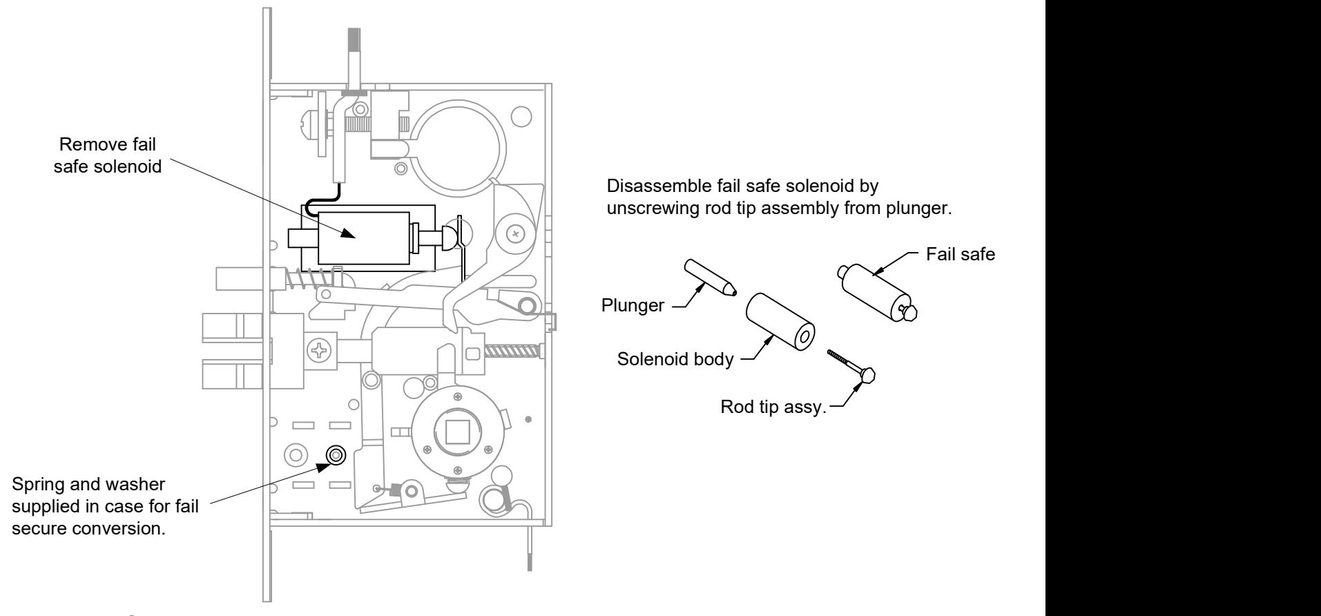
Fail Secure Assembly
Insert washer and spring onto rod tip assembly and screw into plunger until it bottoms out. Insert plunger/rod tip into solenoid.