Z7200 Electrified Cylindrical Locksets Installation Instructions
Open the original PDF document
View PDF

[t] 800.413.8783 ■ 805.494.0622 ■ E-mail: service@sdcsecurity.com ■ 801 Avenida Acaso, Camarillo, CA 93012 ■ PO Box 3670, Camarillo, CA 93011
INSTALLATION INSTRUCTIONS
Z7200 CYLINDRICAL LOCK
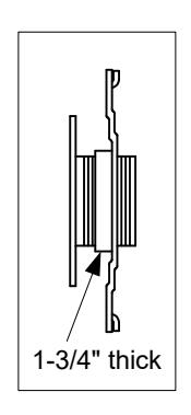
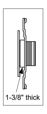
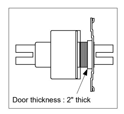
FOR USE ON DOORS 1-3/8" ~ 2" (35mm ~ 51mm) THICK
TOOLS REQUIRED FOR NEW INSTALLATION:
1 philips head screwdriver 1 2-1/8" (54MM) hole saw 1 1" (25.4mm) drill bit 1 5/16" (8mm) drill bit
1 chisel 1 file
OPTIONAL:
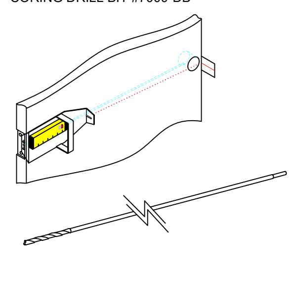
DOOR CORE DRILLING GUIDE #7000-DG & CORING DRILL BIT #7000-DB
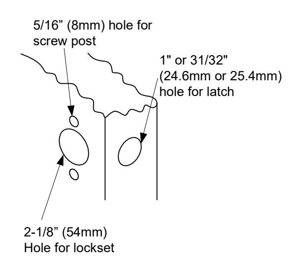
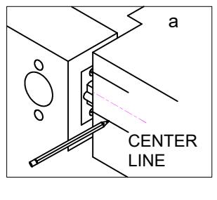
1. MARK DOOR
- a. Mark centerline on door face and door edge (usually 38" from finished floor)
- b. Select backset 2-3/8" or 2-3/4" and mark hole center on door face NOTE: BACKSET ON DOOR FACE MUST BE THE SAME AS BACKSET OF YOUR LOCK.
c. Mark two holes for screw post.
Fold template for High or Low Bevel positioning (reference template)
2. DRILL HOLES


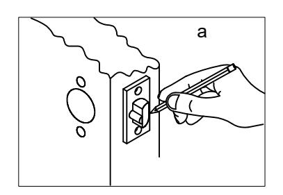
3. INSTALL LATCH
- a. Insert latch in hole and keep it parallel to door face. Mark outline and remove latch
- b. Chisel 1/8" (3mm) deep or until faceplate is flush with door edge.
- c. Insert latch and tighten screws. NOTE: LATCH BOLT BEVEL MUST FACE TOWARDS CLOSING DIRECTION.
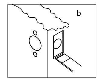
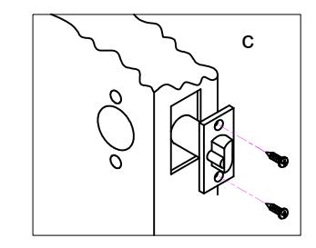
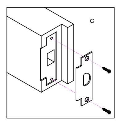
4. INSTALL STRIKE
- a. Close door to mark horizontal line of strike.
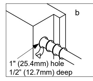
- b. Measure one half of door thickness from door stop to mark vertical center line of strike. Drill 1" (25.4mm) hole, 1/2" (12.7mm) deep at intersection of horizontal and vertical center lines.
- c. Cut out jamb 3/32" (2.4mm) deep or until strike is flush with jamb. Tighten screws securely.
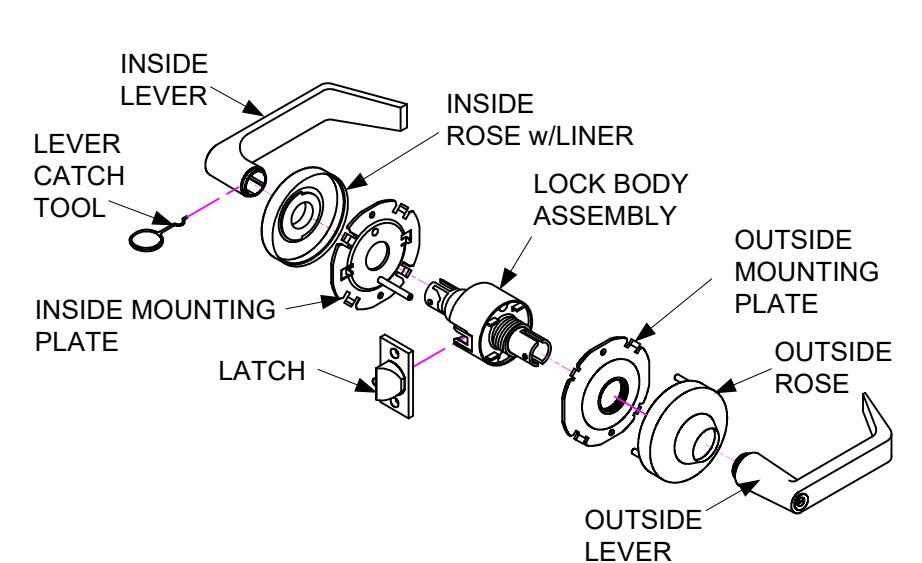
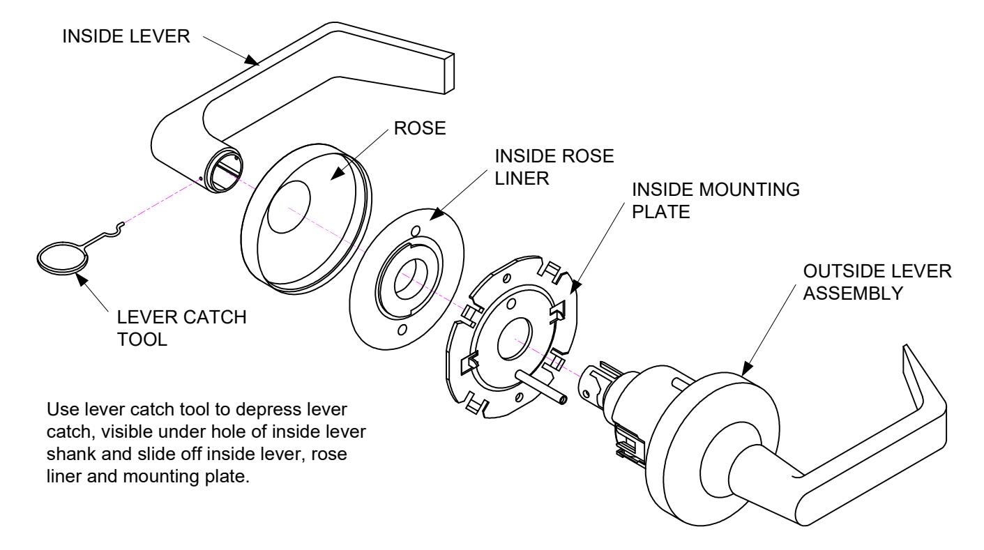
5. REMOVE INSIDE TRIM

6. ADJUST DOOR THICKNESS
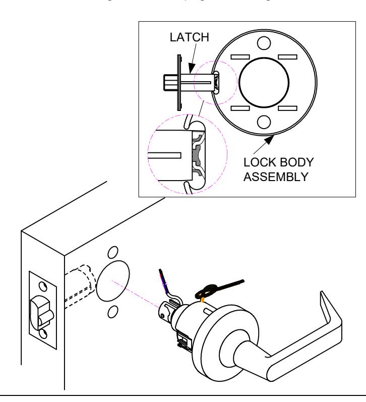
7. INSTALL OUTSIDE LEVER ASSEMBLY
Install outside lever assembly on the door. Make sure tail of latch is engaging with retractor correctly as illustrated. Refer to wire diagram on last page for wiring.
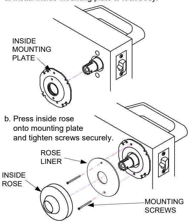
8. INSTALL INSIDE MOUNTING PLATE AND ROSE
a. Install inside mounting plate to lock body.
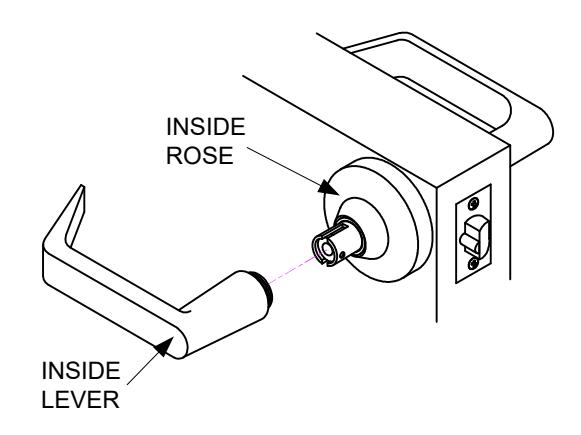
9. INSTALL LEVER
Depress lever catch with tool provided. Push inside lever on completely until catch engages in lever. Confirm lever is secured.

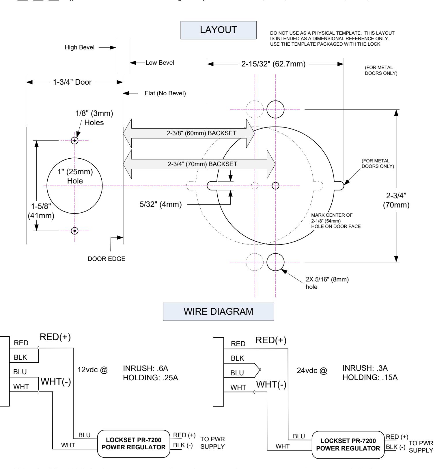
Using the PR-7200 limits the power consumption, reduces operating temperature, and suppresses inductive kickback. (The PR-7200 is only supplied with the Fail-Safe models.)
LATCH STATUS MECHANICAL SWITCH SPDT
3A @ 30VDC
LATCH STATUS
COM = WHT/RED N/C = ORG/RED
N/O = YEL/RED
*Both options cant be used simultaneously.
REQUEST-TO-EXIT MAGNETIC SENSOR 200mA @ 30VAC (RESISTIVE)
COM = GREY
N/C = YELLOW REX N/O = ORANGE