X-09 Combo Motor Replacement Kit
Open the original PDF document
View PDF

X-09TM Combo Motor Replacement Kit (P/N 507101)
Kit Contents
- 1. Combo Motor (1)
- 2. Torx Screws for X-09 Combo Motor (3)
- 3. Flat Head Screws for CDX-09 Combo Motor (2)
- 4. Back Cover Screws (2)
- 5. LOBC (Lock on Back Cover) Pin, Spring, Clip (1 each)
- 6. Fence (1)
- 7. Slide Retainer (1)
- 8. Phillips Head Screw for Slide Retainer (1)
To Remove the Old Motor
Caution: Use of a grounding strap is necessary to prevent electrostatic discharge when performing any maintenance on the X-09 Lock. Please read instructions completely before performing any operation.
- 1. Open the container or door to expose the back cover of the lock.
- 2. Locate the Lock On Back Cover (LOBC) Pin on the back cover. (Figure 1)
- 3. With the container/door open, turn the dial to the left and fully extend the lock bolt.
- 4. Dial the combination(s) to open the lock. When OP is displayed, pull out on the LOBC Pin and continue to hold outward pressure on the LOBC Pin while retracting the lock bolt. If this action is successful, the Pin will "pop" out of the locked position, and the back cover can be removed. (If unsuccessful, repeat until successful.)
- 5. Remove the two back cover screws and remove the back cover.
- 6. Extend the bolt by turning the dial to the left.
- 7. Remove the nut that holds the drive cam to the spindle using a 5/16" nut driver. Because of the clutch in the dial, it may be necessary to hold the drive cam while removing the nut. Remove and save the drive cam.
- 8. Locate the Combo Motor. For X-09 remove the two Torx screws. (This will require a T8 Torx wrench.) For CDX-09 remove the two flat head screws that hold the shield and Combo Motor in place.
- 9. Remove the old motor (and also the shield if CDX-09.) (Figure 2) Note the position of the Combo Motor gear. (Figure 3)
- 10. Remove the fence. (Figure 4)
- 11. Using a small Phillips screw driver, remove the screw that holds the slide retainer. Remove the slide retainer. (Figure 5)
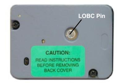
Figure 1 - Lock On Back Cover Pin
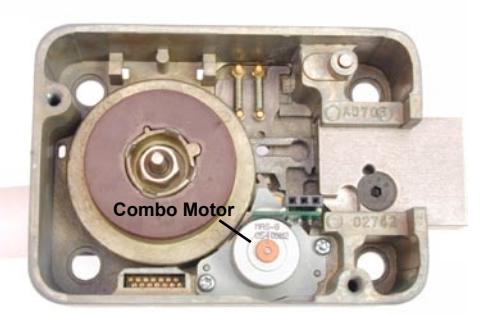
Figure 2 - Locate Combo Motor
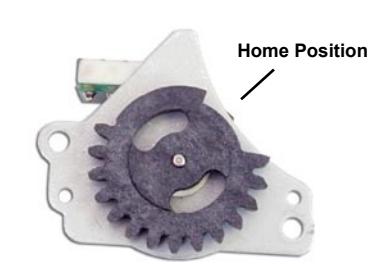
Figure 3 - Note Gear Position
Caution: Do not remove metal gears. If removed, ensure roller remains on post on back of gear, and ensure timing marks of 2 metal gears are aligned. (See Figure 6.)
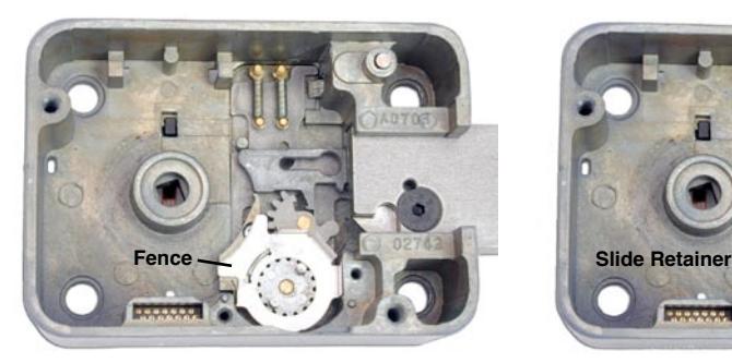

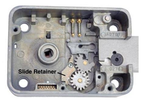
Figure 4 - Remove Fence Figure 5 - Remove Slide Retainer
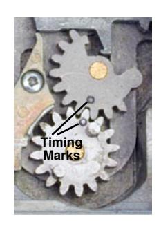
Figure 6 - Do Not Remove Metal Gears
To Install the New Motor
Note:The slide retainer and fence must also be replaced since the old parts will not work with the new Combo Motor.
- 1. Install the new slide retainer. (Extra screw provided.)
- 2. Install the new fence, ensuring that the slot in the fence is seated over the slide retainer.
- 3. Rotate the new Combo Motor gear so that the motor is in the home position and install the new motor. Secure with the two Torx screws for X-09 or two flat head screws for CDX-09. (Extra screws included in kit. Refer to Figures 2 and 3.)
- 4. Replace the drive cam and drive cam retaining nut. Once again, it may be necessary to hold the drive cam while tightening the nut.
- 5. Remove the LOBC Pin from the back cover assembly by taking a pair of wire cutters and cutting the black retainer clip on the Pin. Remove the spring and Pin from the card. This will allow you to install the card and retract the bolt.
- 6. Install the back cover without the LOBC Pin, making sure the connector pins and the spindle hole in the back cover are aligned properly, and push the cover onto the lock case. Insert and tighten the two back cover mounting screws.
- 7. Test the operation of the lock by dialing the combination(s) and retracting the bolt.
- 8. Leave the bolt in the fully retracted position and remove the back cover assembly.
- 9. Insert the cover lock pin through the back cover.
- 10. Install the enclosed cover lock spring and retainer clip onto the cover lock pin. The "fingers" of the retainer clip should be angled away from the cover lock spring, and the retainer clip must be seated in the groove of the cover lock pin. (See Figure 7.)
Caution: Do not push the clip retainer past the small groove in the cover lock pin. If the clip is not located in the pin groove, it can interfere with pulling the bolt or prevent withdrawal of the pin for normal back cover removal.
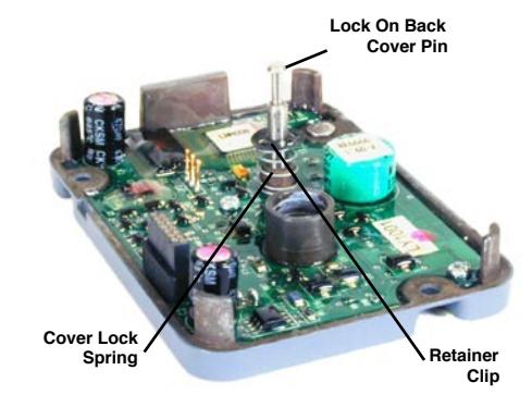
Figure 7 - Back Cover Assembly
11. Make sure the bolt is fully retracted and reinstall the back cover with the cover lock pin in place.
Caution: Take care to align the connectors, the spindle to the hole in the back cover, and the cover lock pin to the keyhole slot in the bolt rack.
- 12. Tighten the mounting screws.
- 13. After restoring the bolt to the extended position, verify that the cover lock pin is fully recessed into the back cover. If not, gently wiggle the cover lock pin to seat it.
- 14. Check the operation of the lock three times before closing the drawer/door and make sure the lock operates smoothly.