Wiring Instructions for 773, 774, 775, 776 Exit Trim Solenoid Locks & 54- Prefix Lever Monitor Switch (Electrolynx Connector System)
Open the original PDF document
View PDF

INSTALLATION INSTRUCTIONS
773, 774, 775, & 776 Electromechanical Exit Trim Motor Locks & 54-Prefix (Lever Monitor Switch) to ElectroLynx™ Connector System
General Description
This instruction manual includes wiring instructions for all 700 series electromechanical trims to ElectroLynx connector system. The correct wiring configuration must be selected depending on type and function of the trim being installed. Refer to table of contents to select appropriate wiring instruction for product being installed.
Important
- Disconnect all input power before beginning installation to prevent electrical shock and equipment damage
- Installer must be a trained, experienced service person
- All wiring must comply with applicable local electrical codes, ordinances and regulations
CAUTION:
The DC voltage applied to the lock must not exceed 13.5VDC for 12 Volt models and 27VDC for 24 Volt models. If the voltage exceeds these values, the motor may be damaged.
Specifications / Functions
Motor
Type: 12 or 24VDC, Intermittent or Continuous Duty Current draw is 400mA inrush / 15mA continuous @12VDC / 24VDC Built-in full wave bridge rectification
Fail Safe Models:
773 without cylinder 775 with cylinder
Fail Secure Models:
774 without cylinder 776 with cylinder
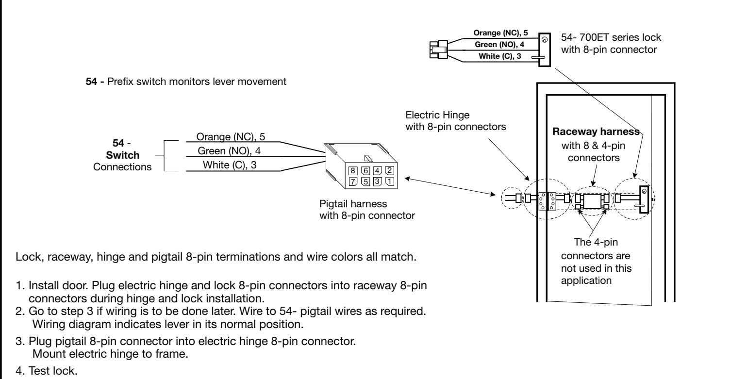
54- (prefix for lever monitor switch) The switch monitors outside lever rotation. Switch contact rating: 2Amp max @ 30VDC.
Installation Notes
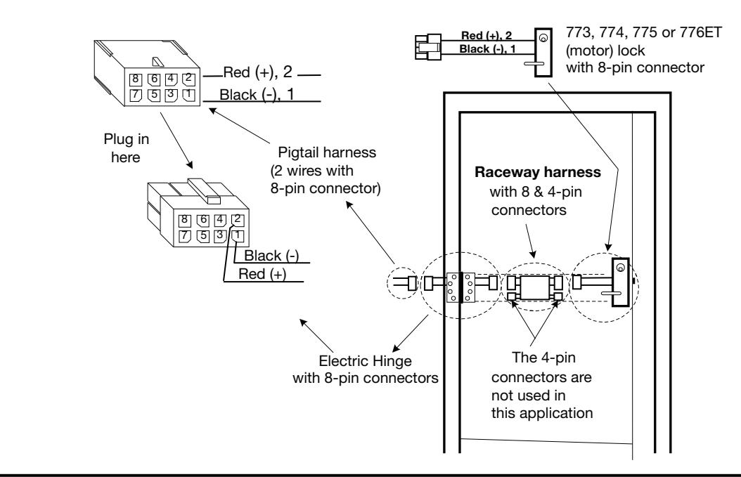
- 1. With new applications, a raceway harness with 8 & 4-pin connectors will be pre-installed inside door by ASSA ABLOY door manufacturer when specified during the ordering process. Raceway harness kits are also available for retrofit applications.
- 2. If door does not have a raceway harness with connectors, consult factory for raceway harness retrofit kit or cut connectors off product and hardwire as required.
- 3. Wiring to pigtail harness is per facility wiring requirement. Follow individual instructions below.
Connector System notes:
The system is designed to be installation friendly with connectors from the electric hinge through the door to the lock. The only wiring is to the loose wires on the pigtail harness assembly on the frame side of the electric hinge.
IMPORTANT :
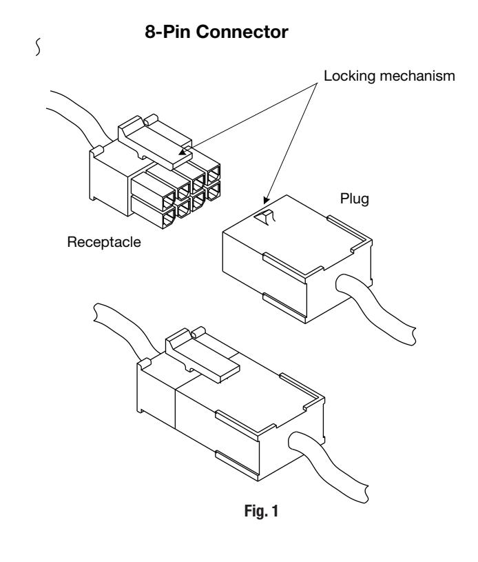
The plug and receptacle connectors are designed to mate and lock together (Fig. 1). Plug the connectors into each other with the locking mechanism aligned as indicated.
Do NOT force connectors on any other way.
01/31/18
773 - 776 ET Installation and wiring instructions
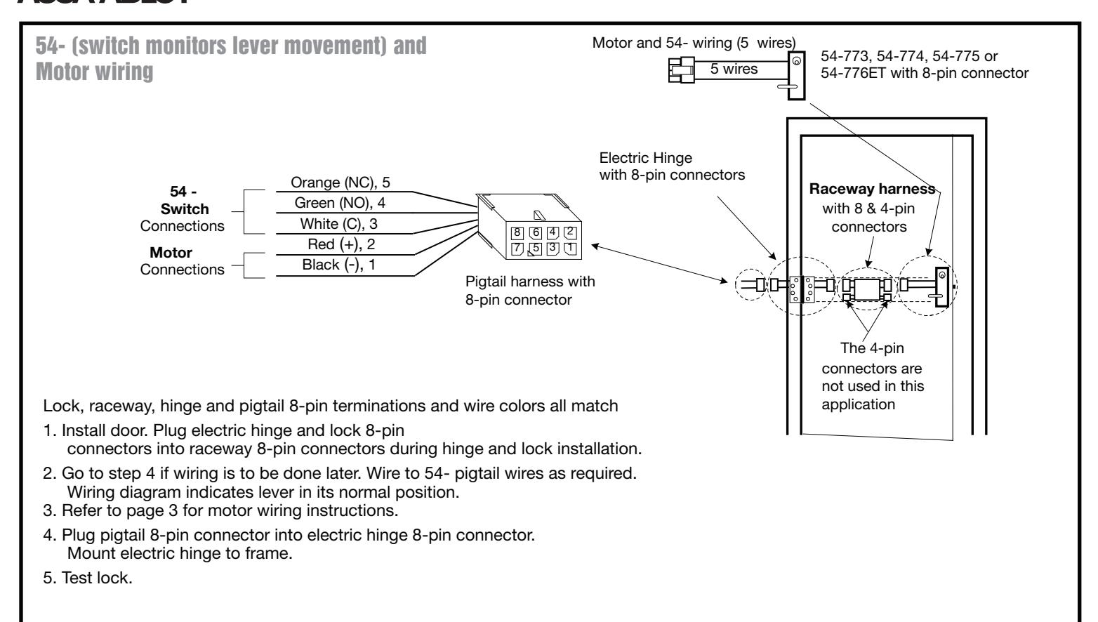
NOTE: Lock, raceway, electric hinge and pigtail 8-pin terminations/wire colors all match.
- 1. Install door. Plug electric hinge and lock 8-pin connectors into raceway 8-pin connectors during lock and hinge installation.
- 2. Wire to pigtail harness.
- 3. Ensure proper supply voltage is being applied at pigtail harness.
CAUTION: The DC voltage applied must not exceed 13.5VDC for 12 Volt models and 27VDC for 24 Volt models.
If the applied voltage exceeds either of these values, the motor may be damaged.
- 4. Plug pigtail harness 8-pin connector into electric hinge 8-pin connector.
- 5. Test lock Fail Secure Power on Unlocks; Fail Safe Power on Locks
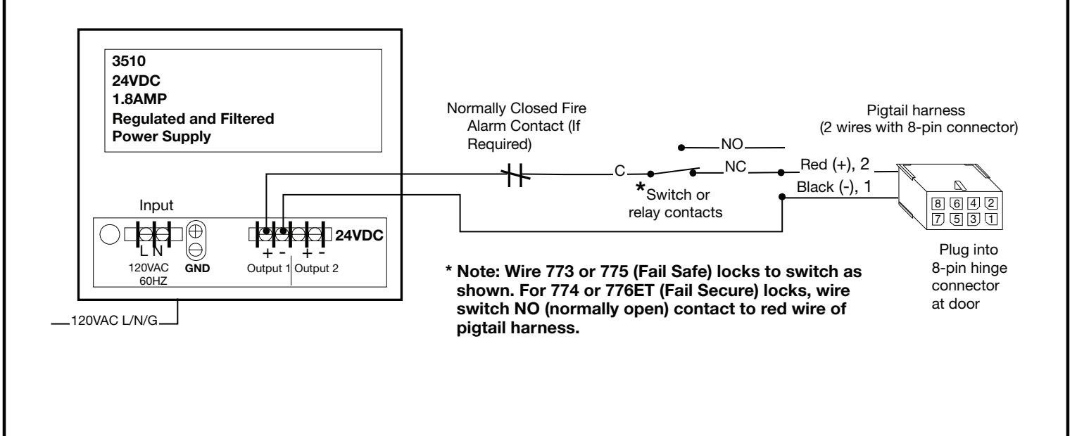
Sample wiring 773 - 776ET motor locks with a 24VDC Regulated and Filtered Power Supply