Wiring Instructions for 2900 Series FIREGUARD Combination Door Closer-Holder and Releasing Device (with Integral Smoke Detector)
Open the original PDF document
View PDFWiring Instructions for the SARGENT ° 2900 Series FIREGUARD® Combination Door Closer-Holder and Releasing Device with Integral Smoke Detector
CAUTION: FAILURE TO INSTALL OR ADJUST PROPERLY MAY RESULT IN INJURY OR DAMAGE. For assistance, contact SARGENT at 800-810-WIRE (9473) or www.sargentlock.com
INSTALLER: LEAVE INSTRUCTION with building owner.
CAUTION
- 1. DISCONNECT ALL POWER BEFORE BEGINNING INSTALLATION TO PREVENT ELECTRICAL SHOCK AND EQUIPMENT DAMAGE.
- 2. INSTALLER MUST BE A TRAINED, EXPERIENCED SERVICE PERSON.
- 3. ALL WIRING MUST COMPLY WITH APPLICABLE LOCAL ELECTRICAL CODES, ORDINANCES AND REGULATIONS.
- 4. MAXIMUM WIRE SIZE IS 18AWG.
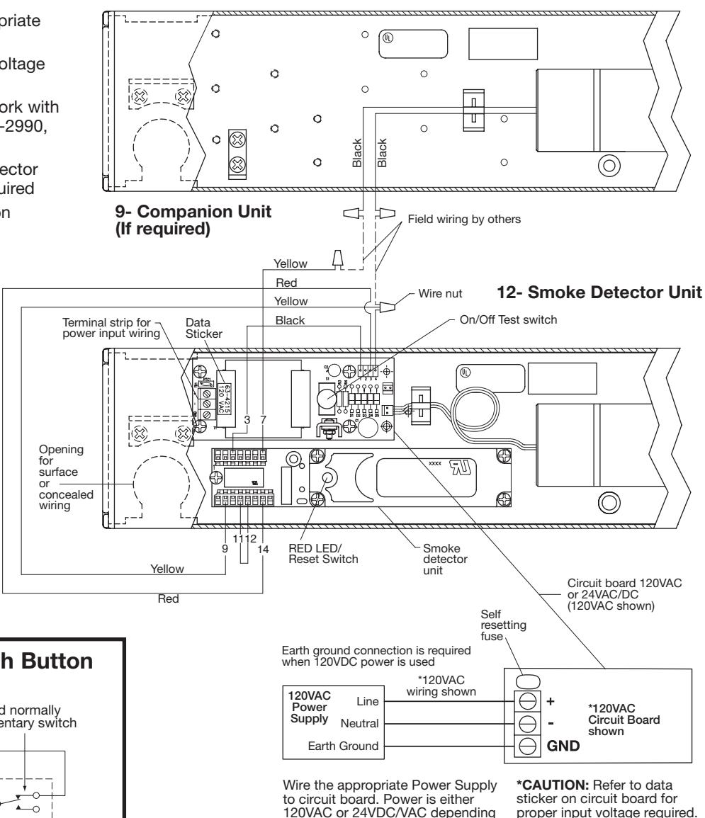
Wiring 12- Units with and without 9- Companion Unit
- Wire 12- smoke detector unit to appropriate power supply and fire alarm
- Refer to data sticker for proper input voltage and current specifications
- 9- Companion units are designed to work with 12- smoke detector units (12-2960, 12-2990, 12-2980) only
- Wire companion unit to 12- smoke detector unit as shown on wiring diagram if required
- Do not disconnect any existing wires on smoke detector unit's terminal strip
- Energize power supply. Current draw .1 AMP per 12- unit.
- Open door(s) to hold-open point. Door(s) should hold open
- Depress On/Off test switch on circuit board. Doors should close and latch
- Adjustment of spring power may be necessary to ensure proper latching
- Depress On/Off test switch to reactivate hold open latch assembly(s)
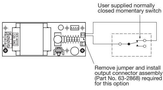
Wiring Optional Remote Push Button
120VAC or 24VDC/VAC depending on circuit board supplied.
wire 24VDC/VAC power supply to + and - terminals on circuit board
proper input voltage required.
Do NOT wire 120VAC power When 24VDC/VAC board is supplied, to 24VDC/VAC circuit board.
A7408B
Smoke Detector Operation and Application
The closer/holder unit includes a 4-wire, photoelectric type smoke detector. It provides: smoke detection, door holder solenoid control, N.O. alarm contact, N.C. supervisory contact and interconnection to other smoke detectors. Field option: one form C auxiliary contact (cut jumper wire between 11 and 12).
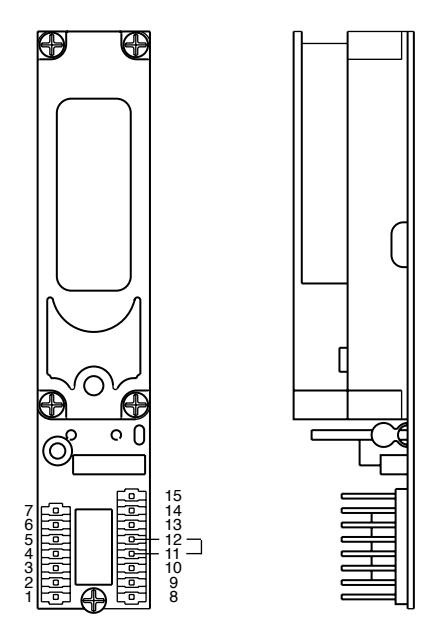
Terminal Inputs and Outputs
- 24VDC input power is applied to terminals 3 (-) and 14 (+) by the adjacent circuit board. Red LED flashes every 8 seconds
- Terminals 1 and 2 provide a normally open (alarm) contact. This contact closes when smoke is detected. Red LED illuminates continuously
- Terminals 5 and 13 provide a normally closed supervisory (trouble) contact. This contact opens when power is lost to the detector circuity. Red LED stops flashing
- Terminals 9 and 6 provide rectified, unfiltered 24VDC to the door holder solenoid. This power is cut in alarm and the door closes
- Terminals 7 and 8 provide rectified, unfiltered 24VDC to auxiliary devices when the detector alarms
- Terminal 10 is rail + output. It is a continuous, rectified, unfiltered 24VDC used for remote detector interconnect applications
- Terminals 8, 9 and 10 may be field configured to a dry form contact by cutting jumper between terminal 11 and 12. Terminal 10 is Common, 9 is N.C. and 8 is N.O. If this is done, Aux.+ is lost; solenoid power must be supplied by a separate source.
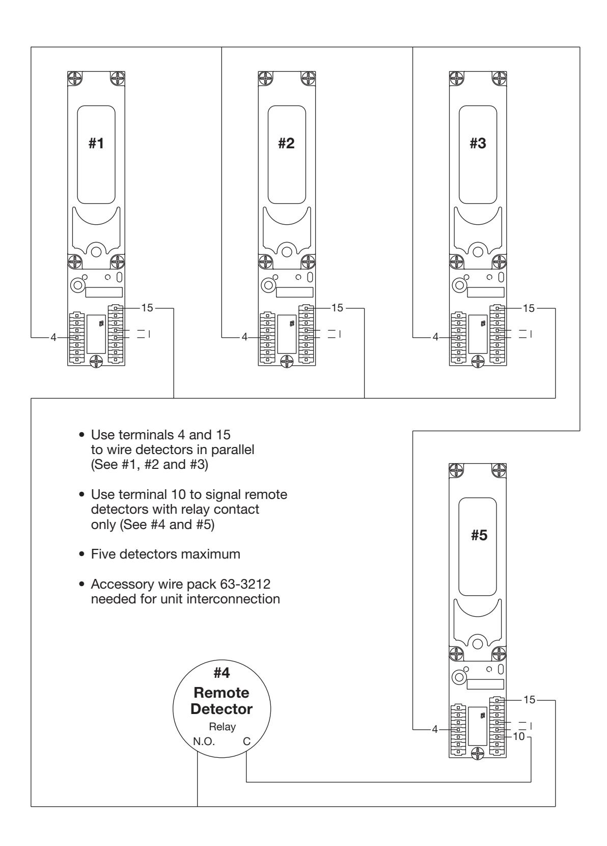
- Terminals 15 and 4 provide interconnections to other detectors (See diagram Pg. 4). Up to five smoke detectors may be interconnected. When a single detector alarms, terminal 15 goes high and any interconnected smoke detector will close its doors. The unit that initiated the alarm will have its LED on. The other interconnected units' LEDs will flash as normal. Refer to interconnection wiring diagram for connections.
Detector Specifications (Part# 63-3210, Revision D)
Type: Photo-Electric Smoke Detector
Complies with UL 228 and UL 268 standards
Power Requirements: 24VDC +/- 10% Nominal Sensitivity: 2.325 +/- 1.055%/FT
Contact Ratings
Alarm and/or Accessory 2.0 AMPS Max. @ 24VDC (Resistive load) 0.6 AMPS Max. @ 120 VAC Trouble Contact 0.5 AMPS Max. @ 24VDC
(Resistive load)
Connection List
| Function | Terminal |
|---|---|
| 24VDC input | 3 (-), 14 (+ |
| Alarm contacts | 1, 2 |
| Solenoid + | 9 |
| Solenoid - | 6 |
| Aux + | 8 |
| Aux - | 7 |
| Interconnect + | 15 |
| Interconnect - | 4 |
| Trouble contacts | 13, 5 |
| +24VDC output (unfiltered) | 10 |
NOTE: Terminals 4, 6 and 7 are same point.
Checkout Procedure
- 1. Turn the power to the unit "On". Red LED pilot light should illuminate at 8 sec. intervals
- 2. Open door to the hold open point. The door should hold open. Manually pull door out of hold open and release. Door should close
- 3. Open door to the hold open position. Depress (maintained type) On/Off "test switch" button on the power supply board. Door should close
- 4. Depress On/Off test switch again. Open door to the hold open position. Inducing smoke into the smoke detector chamber assembly will bring the unit into alarm. The red LED will be continuously illuminated and the door will close. After clearing the smoke chamber, reset unit as follows
Resetting Instructions
- 1. Remote Reset: Cycle main power by turning the facility main power supply OFF then ON. NOTE: If there are other units connected to the same power supply those doors will close. They will have to be reopened returning them to the hold open position
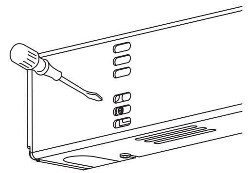
- 2. Local Reset: Insert a small flat head screwdriver through the cover and into the slotted light tube on the smoke detector as shown. Turn screwdriver slightly (about 1/8 turn) clockwise until hitting stop and hold for 2 seconds until the Red LED turns OFF. WARNING: Do not force past the stop. Doing so may damage the smoke detector
Once the detector is reset and the smoke has cleared, the detector's Red LED should flash once every 8 seconds. The door(s) should hold open now
Smoke Detector Maintenance
SARGENT recommends cleaning smoke detectors at least every six months. The frequency of cleaning will depend upon local ambient conditions
The smoke detector in this door closer-holder has been enhanced with a feature that detects when a smoke-sensing chamber requires cleaning due to dirt and dust. The need for cleaning is indicated by the flashing of the Red LED light once per second
• Normal Supervisory Operation — Red LED flashes once every 8 seconds
• Dirty Chamber, needs cleaning — Red LED flashes once every second
• Smoke Detection — Red LED is continuously illuminated
To clean the smoke detector assembly, follow the instructions below:
NOTE: Before servicing the system, notify the proper authorities that the smoke detector system is undergoing maintenance and will be temporarily out of service. Disable the zone undergoing maintenance to prevent unwanted alarms
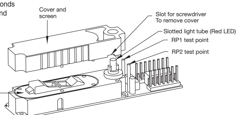
• Remove detector cover and screen assembly using a standard screwdriver. Turn the screwdriver in the cover slot to loosen the cover and carefully rock the cover back and forth until it snaps out of place. See slot location above
Chamber
- Inspect chamber for particles and dust. Vacuum the screen, cover, and photo chamber. Then use clean, compressed air to loosen and blow out any remaining debris
- Before reassembling the detector, be sure all parts are free of dust and debris
- Replace cover and screen, aligning cover snaps, press cover onto chamber until it snaps into place
- Measure and record the test voltage at test points RP1 and RP2 (see above). If the smoke detector is operating normally and was cleaned effectively, the test voltage will be greater than .90VDC and less than 1.58VDC . The test voltage will increase with dust accumulation in the smoke sensing chamber. A difference in test voltages over time will provide an indication of dust accumulation
- Enable system and inform proper authorities system is operational
Interconnection Wiring Diagram
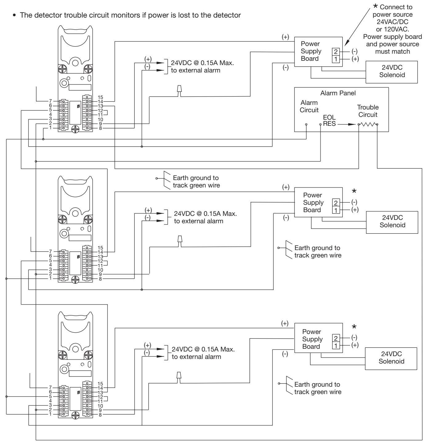
Typical 12- Wiring with Alarm Panel Monitoring (Class A) 4-Wire System by Others
• The alarm circuit monitors if smoke is detected
-
NOTES: 1. End of line (EOL) resistor determined and supplied by others
- 2. Terminal numbers shown correspond to position numbers on terminal strip
- 3. Additional units may be added as required based on the schematic. See electrical data sheet. Do not overload circuits
- 4. Wires are added to header housing by inserting crimped terminal end into housing body until crimped terminal snaps into position. Use accessory wire pack 63-3212
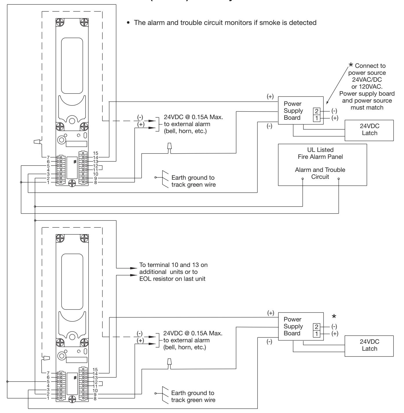
Typical Wiring with Alarm Panel Monitoring (Class B) 2-Wire System
-
NOTES: 1. End of line (EOL) resistor determined and supplied by others
- 2. Power supply voltage must match unit voltage
- 3. Terminal numbers shown correspond to position numbers on terminal strip
- 4. Additional units may be added as required based on the schematic. See electrical data sheet. Do not overload circuits
- 5. Wires are added to header housing by inserting crimped terminal end into housing body until crimped terminal snaps into position. Use accessory wire pack 63-3212

These fire protection devices require correct wiring to function. It is the responsibility of the purchaser to provide correct wiring installation. SARGENT accepts no responsibility for incorrect wiring. Devices wired incorrectly may be damaged and this is not covered under warranty.
Life safety devices including door release devices require correct positioning and appropriate selection for the required task. It is the responsibility of the purchaser to select appropriate hardware and provide professional installation. It is the responsibility of the purchaser to insure that NFPA and other applicable fire codes are met. Door release devices function properly only if the door is free to close. SARGENT accepts no responsibility for incorrect installation of its equipment.
Smoke detectors will not work without power. AC or DC powered smoke detectors will not work if the power supply is cut off for any reason.
All high voltage wiring should be undertaken by a qualified professional licensed electrician. It is the responsibility of the purchaser to insure that installation meets all applicable local and national electrical codes.
Smoke detectors will not sense fires which start where smoke does not reach the detectors. Smoke from fires in chimneys, in walls, on roofs or on the other side of closed doors may not reach the smoke detector and alarm it.
A detector may not detect a fire developing on another level of a building. For this reason, detectors should be located on every level of a building.
Smoke detectors have sensing limitations. Photoelectric detectors sense smoldering fires better than flaming fires. Ionization detectors offer a broad range of fire-sensing capability, but they are better at detecting fast, flaming fires than slow smoldering fires. Because fires develop in different ways, and are often unpredictable in their growth, neither type of detector is always best, and a given detector may not always provide warning of a fire. In general, detectors cannot be expected to provide warnings for fires resulting from inadequate fire protection practices, violent explosions, escaping gas, improper storage of flammable liquids like cleaning solvents, other safety hazards, or arson. Smoke detectors used in high air velocity conditions may fail to alarm due to dilution of smoke densities created by such frequent and rapid air exchanges. Additionally, high air velocity environments may create increased dust contamination, demanding more frequent maintenance.
Smoke detectors do not last forever. Even though detectors are made to last over 10 years, these components could fail at any time. Therefore, test your smoke detector system per NFPA 72E at least semiannually. Clean and take care of your smoke detectors regularly. Taking care of the fire detection system you have installed will measurably reduce your liability risks.
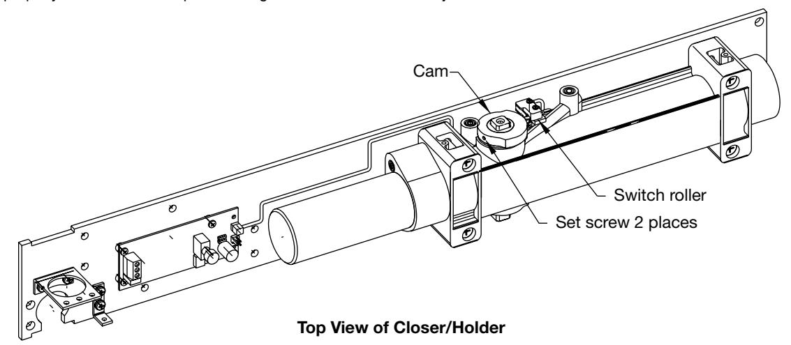
SARGENT Optional 80- Prefix Bypass Hold Open Switch for 2960, 2970 and 2990 Fire Guard
General Information
The 80 Prefix switch allows the initial hold open point to be adjustable from 20 degrees through full door opening. This adjustment is done using a cam on the spindle opposite from where the arm mounts. (Not available with 9- units.)
Adjustment Instructions
A. IMPORTANT
- 1. CAUTION: DISCONNECT ALL INPUT POWER BEFORE BEGINNING INSTALLATION TO PREVENT ELECTRICAL SHOCK AND EQUIPMENT DAMAGE.
- 2. INSTALLER MUST BE A TRAINED, EXPERIENCED SERVICE PERSON.
- 3. ALL WIRING MUST COMPLY WITH APPLICABLE LOCAL ELECTRICAL CODES, ORDINANCES AND REGULATIONS.
B. Installation
- 1. Mount closer/holder per instruction sheet provided.
- 2. Locate switch and cam and loosen both set screws in cam.
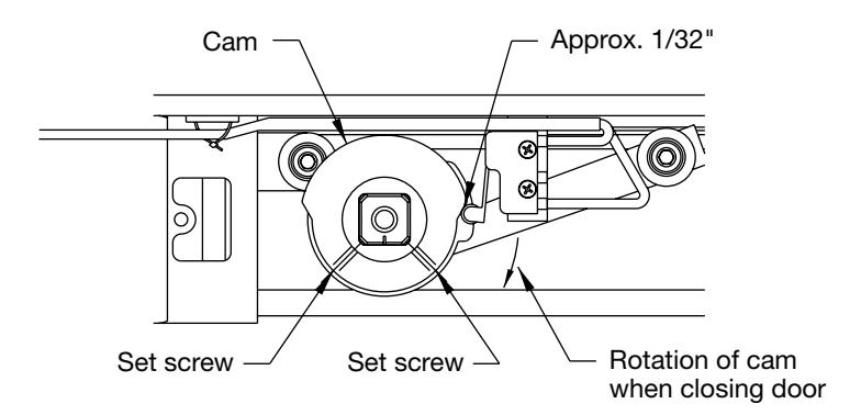
- 3. Open door to desired holding position and hold open with door stop. Rotate cam until switch roller is on lower section of cam and approximately 1/32" from bottom of incline. Cam should be positioned so when door closes, roller on switch will ride up incline of cam operating the switch. Tighten one set screw in cam with hex key and pull door closed.
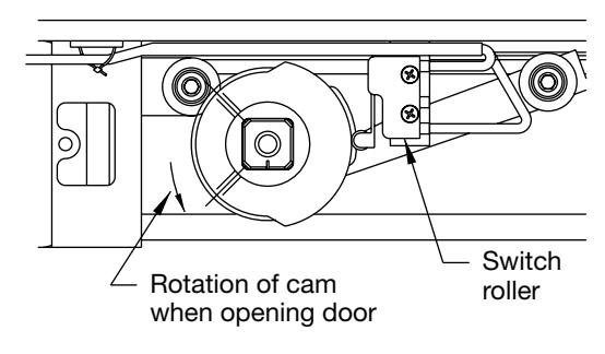
- 4. Pull door open to desired hold open position. When switch roller travels down to bottom of incline, door closer will function as a standard multi-point holder. Depending on door size and closer fall back, cam may need to be adjusted so that the switch roller is positioned properly for desired door operation. Tighten both set screws firmly.
Cam in Door Open Position
Cam in Door Closed Position