Wire Routing-Door Prep Instructions – I-ED00367-Rev10
Open the original PDF document
View PDF

DEVICES COVERED IN THIS DOCUMENT:
LM – Latch Bolt Monitoring * DE – Delayed Egress
MLR – Motorized Latch Retraction (Field Installation Kit 2-649-5007) * AI – Authorized Ingress (not for use with
RX – Request to Exit (Field Installation Kit 2-649-5001) Mortise Exit) *
EU/EL – Electrified Mortise Trim (ordered with 4501N Exit) * only)
* Quick Connects Optional
RX2 – Dual Request to Exit ET – Electric Trim (4500 Series only)
ED – Electric Dogging * OBDE-On-Board Delayed Egress (4500 Series
ELECTRICAL SPECIFICATIONS AND COLOR CODES FOR WIRES
For use with all Hager monitored exit device modifications.
Request to Exit (RX) switch monitors egress by push bar activation of the exit device. Latch Bolt Monitoring (LM) switch monitors the latch mechanism of the exit device.
Authorized Ingress (AI) switch monitors ingress by trim or key retraction of the exit device latch.
| Request to Exit (RX) | Latch Bolt Monitoring (LM) | Authorized Ingress (AI) | |
|---|---|---|---|
| Electrical | SPDT Monitoring Switch | SPDT Monitoring Switch | SPDT Monitoring Switch |
| Specification | |||
| Maximum Contact Rating: | Maximum Contact Rating: | Maximum Contact Rating: | |
| 3 AMP @125VAC | 3 AMP @125VAC | 3 AMP @125VAC | |
| 2 AMP @ 30VDC | 2 AMP @ 30VDC | 2 AMP @ 30VDC | |
| Color Code | Yellow Wire – Common | Black Wire – Common | Black Wire – Common |
| for wires | Red Wire – Normally Open | White Wire – Normally Open | Orange Wire – Normally Open |
| Grey Wire – Normally Closed | Red Wire – Normally Closed | Purple Wire – Normally Closed | |
| Wire Gauge – #22 AWG | Wire Gauge – #22 AWG | Wire Gauge – #22 AWG |
WIRE ROUTING AND DOOR PREP INSTRUCTIONS
- 1. Follow exit device instructions and template to prepare door and frame for installation.
-
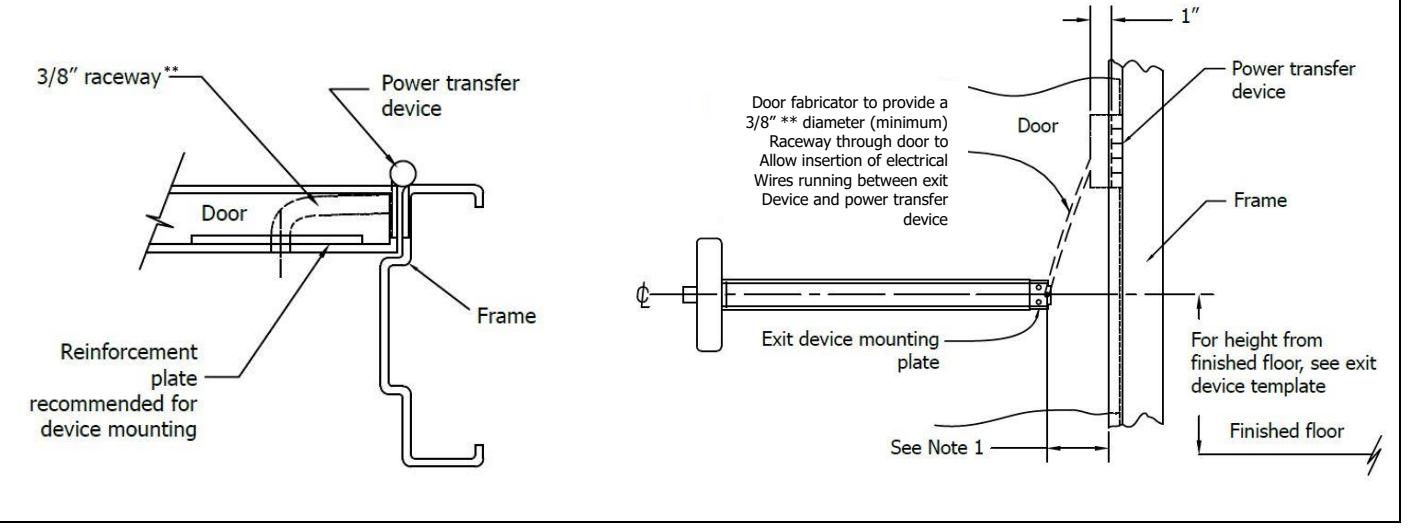
2. Door fabricator to provide a 3/8" ** diameter (minimum) raceway through door to allow insertion of electrical wires running between exit device and power transfer device (electric hinge).
- ** Quick Connects Require 5/8" Raceway

Notes:
-
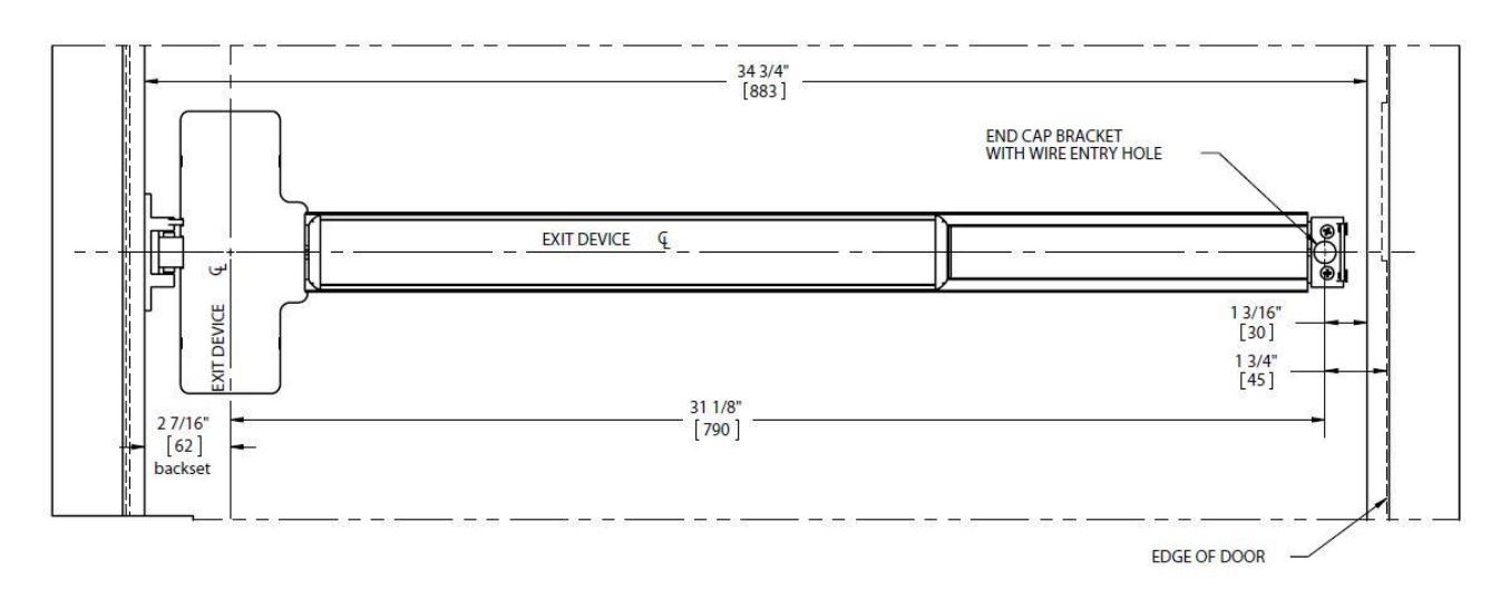
1. Wire entry hole location on door (see example below):
- a. This dimension depends on the backset and specific door application. Please see exit device instructions to determine backset and exit device location.
- b. This dimension also depends on whether the device length has been field modified. Please the Hager website Electrified Products section for detail about how devices can be field modified.
Example – Single 3-foot door with RIM device. Please refer to individual 4500/4600 Series Installation template for approprite dimension.
-
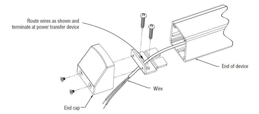
2. Mount exit device end cap and wires:
- a. Follow exit device instructions and template to install end cap bracket.
- b. Route wires as shown in diagram below and terminate at power transfer device.
- 3. The EU/EL functions for the Mortise Exit Device are available for the Night Latch Version only (4501N). These electrifications are ordered with the device but are included in the Mortise Exit Lock Body.
- 4. The MLR, DE, OBDE and ED all occupy the same space in the push bar. None of these can be done in conjunction with each other or with cylinder dogging or any Alarm Kit functions.

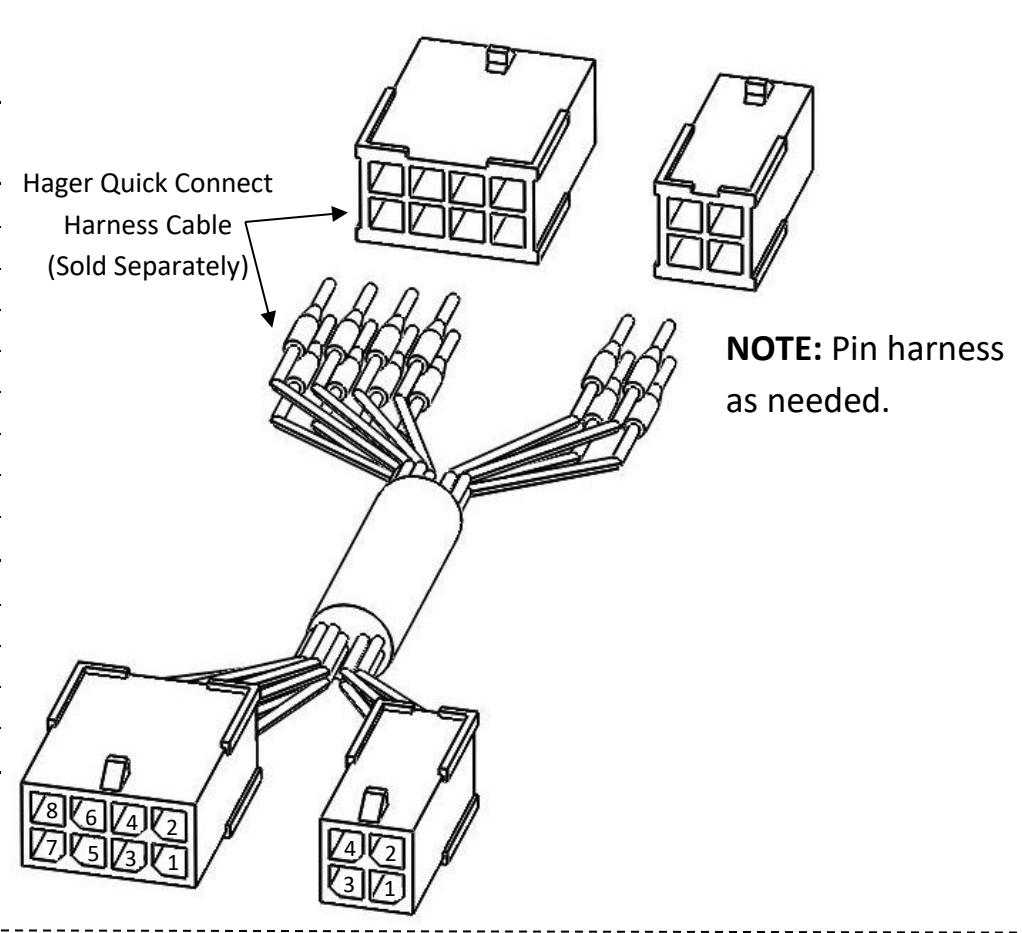
QUICK CONNECTS
- Quick connects are installed on the wires from the exit device electrification options. These quick connects are compatible with Hager Quick Connect Harness Cable which can be used to plug into Hager hinges with quick connects to provide quick and accurate wiring of the door.
| Quick Connect | ||||
|---|---|---|---|---|
| Harness Cable Pinning | ||||
| 8 Pin | Wire Color | |||
| Pin # 1 | Black | |||
| Pin # 2 | Red | |||
| Pin # 3 | White | |||
| Pin # 4 | Green | |||
| Pin # 5 | Orange | |||
| Pin # 6 | Blue | |||
| Pin # 7 | Brown | |||
| Pin # 8 | Yellow | |||
| 4 Pin | Color | |||
| Pin # 1 | Violet | |||
| Pin # 2 | Gray | |||
| Pin # 3 | Pink | |||
| Pin # 4 | Tan | |||
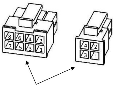
Hager Exit Quick Connect Terminals
| 4501/4601 Quick Connect Pinning | |||
|---|---|---|---|
| 8 Pin | Function | Wire Color | |
| Pin # 1 | Power* | Color* | *Color (Power) |
| Pin # 2 | Power* | Color* | • Black (ED) |
| Pin # 3 | RX (Com) | Yellow | • White (MLR) |
| Pin # 4 | RX (N/O) | Red | • Blue (ELR) |
| Pin # 5 | RX (N/C) | Gray | |
| Pin # 6 | AI (Com) | Black | |
| Pin # 7 | AI (N/O) | Orange | |
| Pin # 8 | AI (N/C) | Purple | |
| 4 Pin | Function | Color | |
| Pin # 1 | Blank | Blank | |
| Pin # 2 | LM (Com) | Black | |
| Pin # 3 | LM (N/O) | White | |
| Pin # 4 | LM (N/C) | Red | |