WD8600, 12-WD8600, NB-WD8600, NB-12-WD8600 Concealed Vertical Rod Exit Device Installation Instructions
Open the original PDF document
View PDFInstructions for Installing SARGENT WD8600 & 12-WD8600 Series Concealed Vertical Rod Exit Device FOR ASSISTANCE, CALL SARGENT AT 1-800-727-5477.
Verify the correct exit device is being installed on the correct door. Function, finish and size should all be verified.
Note: Before removing door from hinges, determine the gap between top of door and frame. Determine smallest gap between bottom of door and high point of floor or threshold as door swings.
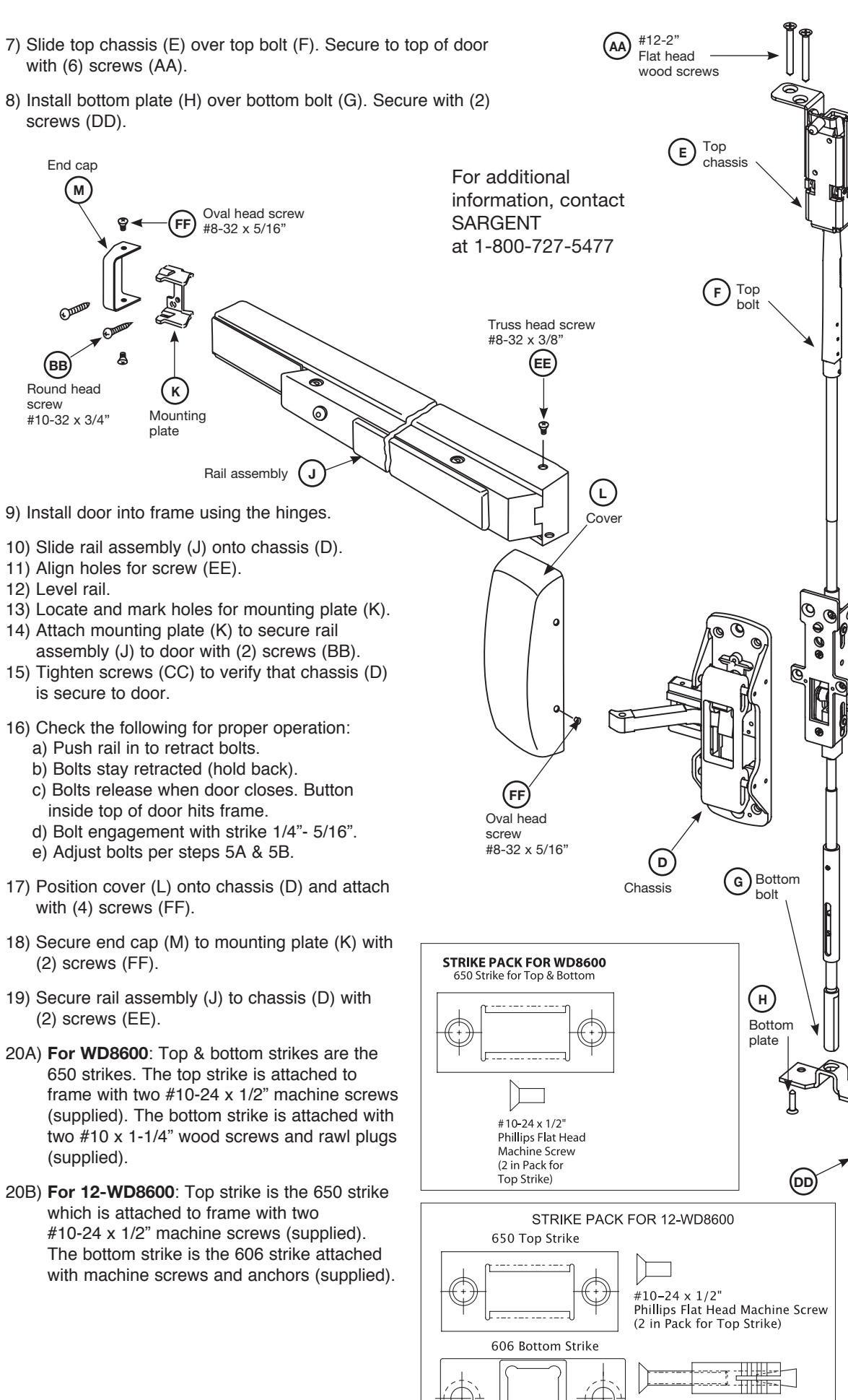
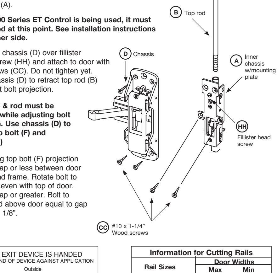
(D) Chassis
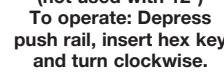
#10 x 1-1/4"
Wood screws
This information is needed for step #5. Remove door from the frame.
1) Pilot drill as required during installation. Note: If 100 Series Auxiliary Control is being used, it must be installed at this point. See installation instructions on the other side.
- 2) Install FILLISTER HEAD screw (HH), inner chassis, as shown
- 3) Attach inner chassis w/mounting plate (A) to door with (2) screws (CC)
- 4) From top of door, screw top rod (B) into inner chassis (A) and from bottom of door, screw bottom rod (C) into inner chassis (A).
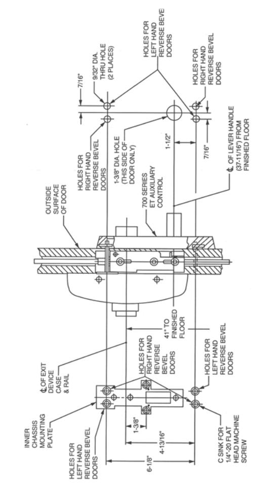
Note: If 700 Series ET Control is being used, it must be installed at this point. See installation instructions at the far right.
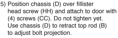
5) Position chassis (D) over fillister head screw (HH) and attach to door with (4) screws (CC). Do not tighten yet. Use chassis (D) to retract top rod (B) & bottom rod (C) to adjust bolt projection.
Note: Bolts & rods must be retracted while adjusting bolt projection. Use chassis (D) to retract top bolt (F) & top rod (B) and bottom bolt (G) & bottom rod (C).
- 6A) Adjusting top bolt (F) projection
- 1) 1/8" gap or less between door top and frame. Rotate bolt to make even with top of door.
- 2) 1/8" gap or greater. Bolt to extend above door equal to gap minus1/8".
-
6B) Adjusting bottom bolt (G) projection
- 1) 1/8" gap or less between door bottom & high point. Rotate bolt to make even with bottom of door.
- 2) 1/8" gap or greater. Bolt to extend below door equal to gap minus 1/8".
SARGENT
ASSA ABLOY
(F)
Top bolt
(A) Inner chassis
plate
Fillister head
(G) Bottom
screw
w/mounting
© Bottom
is secure to door. a) Push rail in to retract bolts. with (4) screws (FF).
- (2) screws (FF).
- (2) screws (EE)
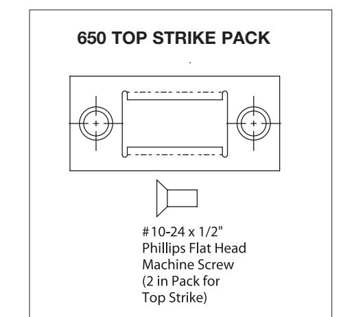
- 650 strikes. The top strike is attached to frame with two #10-24 x 1/2" machine screws (supplied). The bottom strike is attached with two #10 x 1-1/4" wood screws and rawl plugs (supplied).
- which is attached to frame with two #10-24 x 1/2" machine screws (supplied). The bottom strike is the 606 strike attached with machine screws and anchors (supplied).
Instructions for SARGENT WD8600, 12-WD8600, NB-WD8600 and NB-12-WB 8600 with 700 Series ET Controls
See other side for 100 Series Auxiliary Control
hassis (D) to door. attached through the doo e screws (GG) as shown h က
Round Head Wood Screw (2 in Pack for End Cap Mounting Bracket)
1/4" x 1/2" Phillips Flat Head Wood Screw (2 in Pack for Bottom Plate )

Flat Head Wood Screw (4 in Pack for Top Case Mounting Bracket)

Flat Head Wood Screw (6 in Pack for Chassis Mounting and Inner Chassis w/Mounting Plate)

#8-32 x 3/8" Phillips Truss Head Machine Screw (2 in Pack for Chassis to Rail on All Doors)
#8-32 x 5/16" Phillips Oval Head Machine Screw (10 in Pack for All Covers
ET Mounting Screw (1/4" -20 x 2-3/8" ph. fl. hd. Machine Screw 2 pieces
For 1-3/4" Door Length Shown Size Varies by 1/4" Depending on Width of Cladding or Inside Panel

(#10-24 x 3/8" ph. fillister hd.
ASSA ABLOY, the global leader in door opening solutions
Machine Screw and
Instructions for Installing SARGENT NB-WD8600 & 12-NB-WD8600 Series Concealed Vertical Rod Exit Device FOR ASSISTANCE, CALL SARGENT AT 1-800-727-5477.
Verify the correct exit device is being installed on the correct door.
Function, finish and size should all be verified.
1) Pilot drill as required during installation.
Note: Before removing door from hinges, determine the gap between top of door and frame.
This information is needed for step #5. Remove door from the frame.
Note: If 100 Series Auxiliary Control is being used, it must be installed at this point. See installation instructions at the far right.
- 2) Install FILLISTER HEAD screw (HH), inner chassis, as shown
- 3) Attach inner chassis w/mounting plate (A) to door with (2) screws (CC)
- 4) From top of door, screw top rod (B) into inner chassis (A).
Note: If 700 Series ET Control is being used, it must be installed at this point. See installation instructions on the other side.
Note: Bolt & rod must be retracted while adjusting bolt projection. Use chassis (D) to retract top bolt (F) and top rod (B)
- 6) Adjusting top bolt (F) projection
- 1) 1/8" gap or less between door top and frame. Rotate bolt to make even with top of door.
- 2) 1/8" gap or greater. Bolt to extend above door equal to gap minus 1/8".
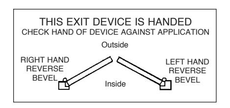
| THIS EXIT DEVICE IS HANDED CHECK HAND OF DEVICE AGAINST APPLICATION | ||||
|---|---|---|---|---|
| Outside | ||||
|
RIGHT HAND
REVERSE BEVEL |
Inside |
LEFT HAND
REVERSE BEVEL |
||
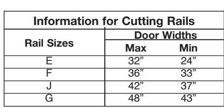
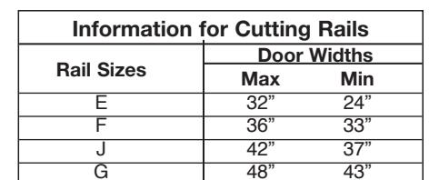
| Information for Cutting Rails | |||
|---|---|---|---|
| Rail Sizes | Door Widths | ||
| Max | Min | ||
| Е | 32" | 24" | |
| F | 36" | 33" | |
| J | 42" | 37" | |
| G | 48" | 43" | |
(F)
Top bolt

ASSA ABLOY, the global leader in door opening solutions
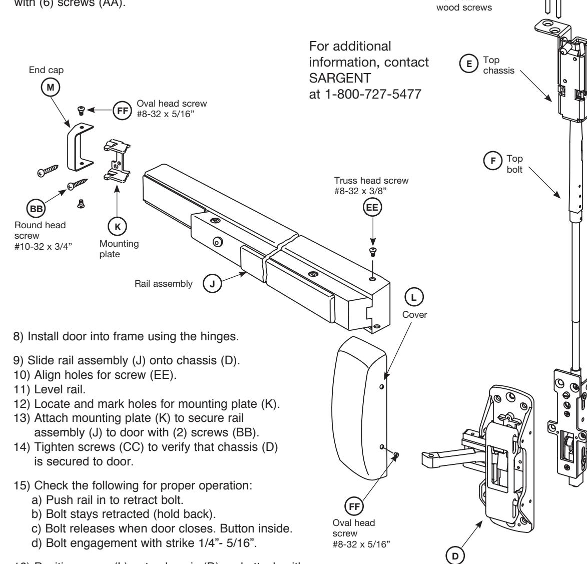
7) Slide top chassis (E) over top bolt (F). Secure to top of door with (6) screws (AA).
16) Position cover (L) onto chassis (D) and attach with
17) Secure end cap (M) to mounting plate (K)
18) Secure rail assembly (J) to chassis (D) with
19) For NB-WD8600 & 12-NB-WD8600, 650 top
#10-24 x 1/2" machine screws (supplied).
Note: To be fire rated, 12-NB-WD8600 Series Exit
Devices require installation of thermal pin.
strike is attached to frame with two
(4) screws (FF).
(2) screws (EE).
with (2) screws (FF).
Chassis
(AA) #12-2"
Instructions for SARGENT WD8600, 12-WD8600, NB-WD8600 and NB-12-WB 8600 with 100 Series Auxiliary Controls See other side for 700 Series ET Control
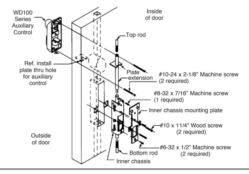
Note: For WD100 Series Auxiliary Control, the following steps are required prior to Step #2 of this instruction sheet
STEP 1
Through the cut out for the inner chassis, slide the extension into door with reduced diameter down.
STEP 2
Insert inner chassis in the door cutout and insert reduced end of extension in top threaded bushing on inner chassis. Attach with #8-32 x 7/16" Phillips oval head machine screw.
From the outside of door through the cutout, install plate onto extension.
STEP 4
Attach inner chassis mounting plate to inner chassis with (2) #6-32 x 1/2" flat head screws.
STEP 5
Attach 100 Series Auxiliary Control to door with (2) #10-24 x 2-1/8" oval head machine screws.

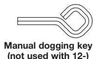
Manual dogging key
(AA)
#12-2" Phillips Flat Head Wood Screv (4 in Pack for Top Case depress push rail, insert hex key Mounting Bracket)

with fire rated devices.
(not used with 12-) To operate:
(or cylinder key when used) and turn clockwise. Not furnished
#10 x 1-1/4" Phillips Flat Head Wood Screw (6 in Pack for Chassis Mounting and Inner Chassis w/Mounting
Truss Head Machine Screw (2 in Pack for Chassis to Rail on All Doors)
#8-32 x 5/16" Phillips Oval Head Machine
Screw (10 in Pack
for All Covers)
ET Mounting Screw (1/4" -20 x 2-3/8" ph fl hd Machine Screw 2 pieces
For 1-3/4" Door Length Shown Size Varies by 1/4" Depending on Width of Cladding or Inside Panel
Aligning and inner
chassis screw (#10-24 x 3/8"
ph. fillister hd. machine
screw,1 pcs)
© SARGENT Manufacturing Company A3937H 3/12