WD-7000 and 12-WD7000 Wood Door Concealed Vertical Rod Multi-Point Lock Installation Instructions
Open the original PDF document
View PDF


Table of Contents
| 1 | Warnings | 2 |
|---|---|---|
| 2 | General Description | 3 |
| 3 |
WD-7000 & 12-WD7000 Series Concealed Vertical Rod Latch Device-Installation Instructions
4-6 |
|
| 4 | NB-WD7000 & 12-NB-WD7000 Series Concealed Vertical Rod Latch Device-Installation Instructions | 7-9 |
| 5 |
Classroom Function Series
10-11 |


Warnings Changes or modifications to this unit could void the user's authority to operate the equipment.

Important: Any retrofit or other field modification to a fire rated opening can potentially impact the fire rating of the opening, and SARGENT Manufacturing makes no representations or warranties concerning what such impact may be in any specific situation. When retrofitting any portion of an existing fire rated opening, or specifying and installing a new fire-rated opening, please consult with a code specialist or local code official (authority having jurisdiction) to ensure compliance with all applicable codes and ratings

2 General Description
The 7000 Series Multi-Point Lock is ideal for security applications and joins the SARGENT line of multi-point door security devices. Eliminating the need for automatic flushbolts and coordinators, the 7000 Series provides flexibility, simplicity, strength, durability, aesthetics and innovation and is perfect for a wide variety of applications including conference rooms, commercial office buildings, convention centers, upscale condominiums and residential applications, medical and educational institutions where exit devices are not required.
7000 Series Vertical Rod locks are available for aluminum, wood and metal doors. Single point top latching can also be specified, eliminating the bottom strike and the additional installation work required with a bottom bolt. The single point device is specified with the NB- option. Rods are retracted by dual mounted controls with a variety of functions available.
The 7000 Series is available for fire rated openings as a 12- for wood or metal doors. Thermal pin requirements for fire rated doors:
- Double doors with two point latching on each do not require thermal pins
- Double doors with single point latching (NB-) on each require a total of 2 thermal pins, one thermal pin (supplied) for each device
- Single door applications: contact factory
See the Sargent 7000 Series Catalog for more information, call 1-800-727-5477, or visit www.sargentlock.com
Tools Required - (Same for all Series Products)
- Phillips screw driver
- Slotted screw driver
- Drill with bits

3 WD-7000 & 12-WD7000 Series-Installation Instructions

Note: For 100 Series auxiliary controls and ELR (Electric Latch Retraction) Option: Ensure all required door preparation has been completed prior to hardware installation.
A) Door Preparation
1. Verify Hand and Bevel of Door -(Figure 1)
- Check hand of door. (the lock may be handed).
- Door should be fitted and hung.
- Verify box label for size of the lock, function and hand.
- Change handing if necessary.
2. Door Preparation
If door is not pre-drilled, prepare door according to the appropriate template # 4624. Refer to templates at www.sargentlock.com.
3. Hardware Supplied:
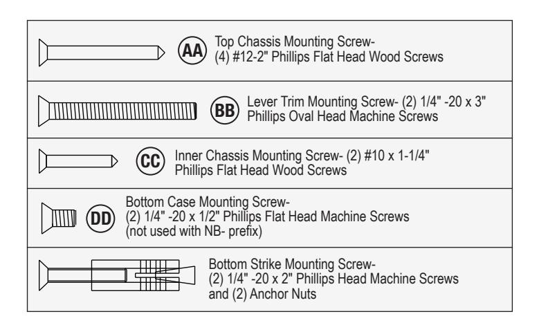
Figure 1: Handing
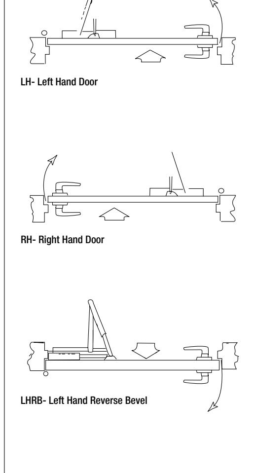
RHRB- Right Hand Reverse Bevel
3

A
Top Bolt & Rod Assembly
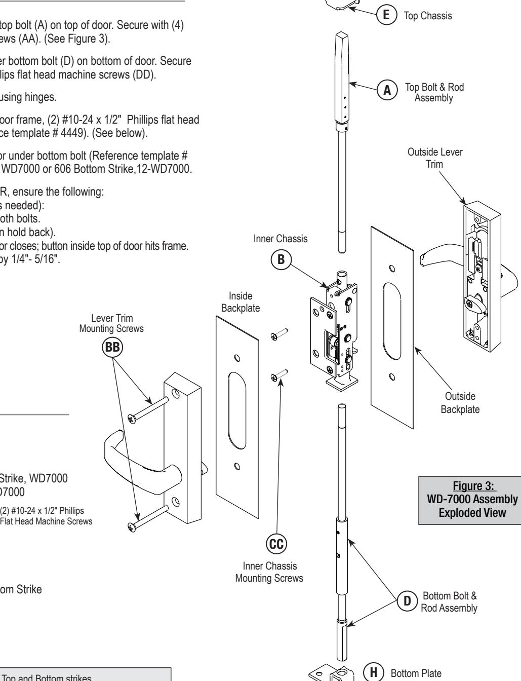
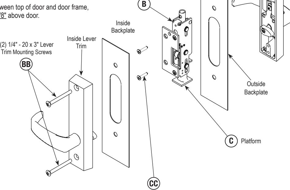
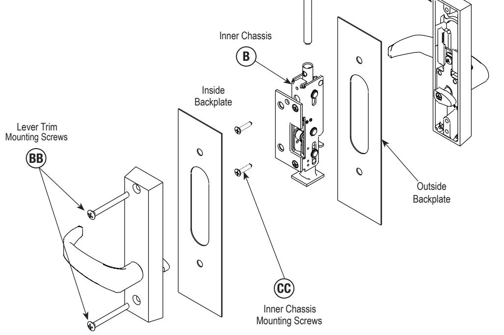
Figure 2: WD-7000 Assembly Exploded View
Outside Lever Trim
WD-7000 & 12-WD7000 Series-Installation Instructions-Continued
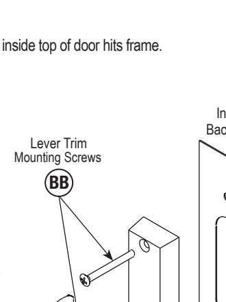
B) Installation 1. Measure gap between top of door & frame and bottom of door & floor before removing door from hinges. (See Steps 5-6). 2. Attach inner chassis (B) to door with (2) #10 x 1-1/4" Phillips flat head wood mounting screws (CC). (See Figure 2). 3. Screw top rod (A) and bottom rod (D) into inner chassis (B) from top and bottom of door. 4. Place trim backplates between lever trim and door surfaces with
- unfinished side toward the door surface. Insert spindle thru 1-1/4" hole. Spindle cams must be UNDER inner chassis platform (C). Insert lever trim mounting screws, 1/4"-20 x 3" (BB) through trimplate and tighten.
- 5. Use inside trim to adjust top bolt and rod assembly (A).
- For 1/8" GAP OR LESS between top of door and door frame, rotate bolt even with top of door.
- For 1/8" GAP OR GREATER between top of door and door frame, rotate bolt to gap space minus 1/8" above door.
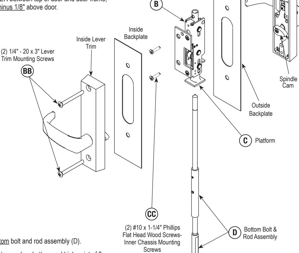
Inner Chassis
- 6. Use inside trim to adjust bottom bolt and rod assembly (D).
- For 1/8" GAP OR LESS between door bottom and high point of floor, rotate bolt to make even with bottom of door.
- For 1/8" GAP OR GREATER between door bottom and high point of floor, rotate bolt to gap space minus 1/8" below door.
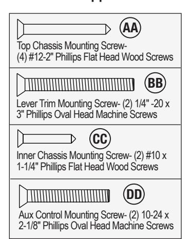
AA
(4) #12-2" Flat Head Wood Screws- Top Chassis Mounting Screws
3 WD-7000 & 12-WD7000 Series-Instructions- Continued
B) Installation- Continued
- 7. Slide top chassis (E) over top bolt (A) on top of door. Secure with (4) #12-2" flat head wood screws (AA). (See Figure 3).
- 8. Install bottom plate (H) over bottom bolt (D) on bottom of door. Secure with (2) 1/4"-20 x 1/2" Phillips flat head machine screws (DD).
- 9. Install door into the frame using hinges.
- 10. Attach 650 Top Strike to door frame, (2) #10-24 x 1/2" Phillips flat head machine screws (Reference template # 4449). (See below).
- 11. Attach bottom strike to floor under bottom bolt (Reference template # 4449). 650 Bottom Strike, WD7000 or 606 Bottom Strike,12-WD7000.
- 12. BEFORE CLOSING DOOR, ensure the following:
(Adjust bolts per Step 5 as needed):
- a) Either lever retracts both bolts.
- b) Bolts stay retracted (in hold back).
- c) Bolts release when door closes; button inside top of door hits frame.
- d) Bolts engage strikes by 1/4"- 5/16".

C) Strikeplates
650 Top Strikeplate
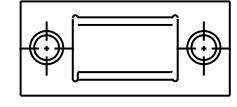
650 Top Strike, WD7000 or 12-WD7000

606 Bottom Strikeplate
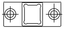
606 Bottom Strike

STRIKE PACK, WD7000: 650 Strike (2), Top and Bottom strikes. Top: #10-24 x 1/2" PH FL HD MS (2);
Bottom: 1/4-20 x 2" PH FL HD MS (2) and anchor nuts (2)
STRIKE PACK, 12-WD7000: 650 Top Strike (1), #10-24 x 1/2" PH FL HD MS (2); 606 Bottom Strike (1), 1/4-20 x 2" PH FL HD MS (2) and anchor nuts (2)
DD
(2) 1/4" -20 x 1/2" Phillips Flat Head Machine Screws for Bottom Plate

NB-WD7000 & 12-NB-WD7000 Series-Installation Instructions (Less Bottom Rod) 4

Note: For 100 Series auxiliary controls and ELR (Electric Latch Retraction) Option: Ensure all required door preparation has been completed prior to hardware installation.
12-NB-WD70000 Fire-rated devices require installation of thermal pins for fire rating. Pairs of doors ONLY. NOT AVAILABLE for single door application.
A) Door Preparation
1. Verify Hand and Bevel of Door -(Figure 4)
- Check hand of door. (The lock may be handed).
- Door should be fitted and hung.
- Verify box label for size of the lock, function and hand.
- Change handing if necessary.
2. Door Preparation
If door is not pre-drilled, prepare door according to the appropriate template. Refer to templates at www.sargentlock.com.
3. Hardware Supplied:
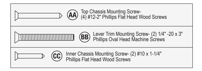
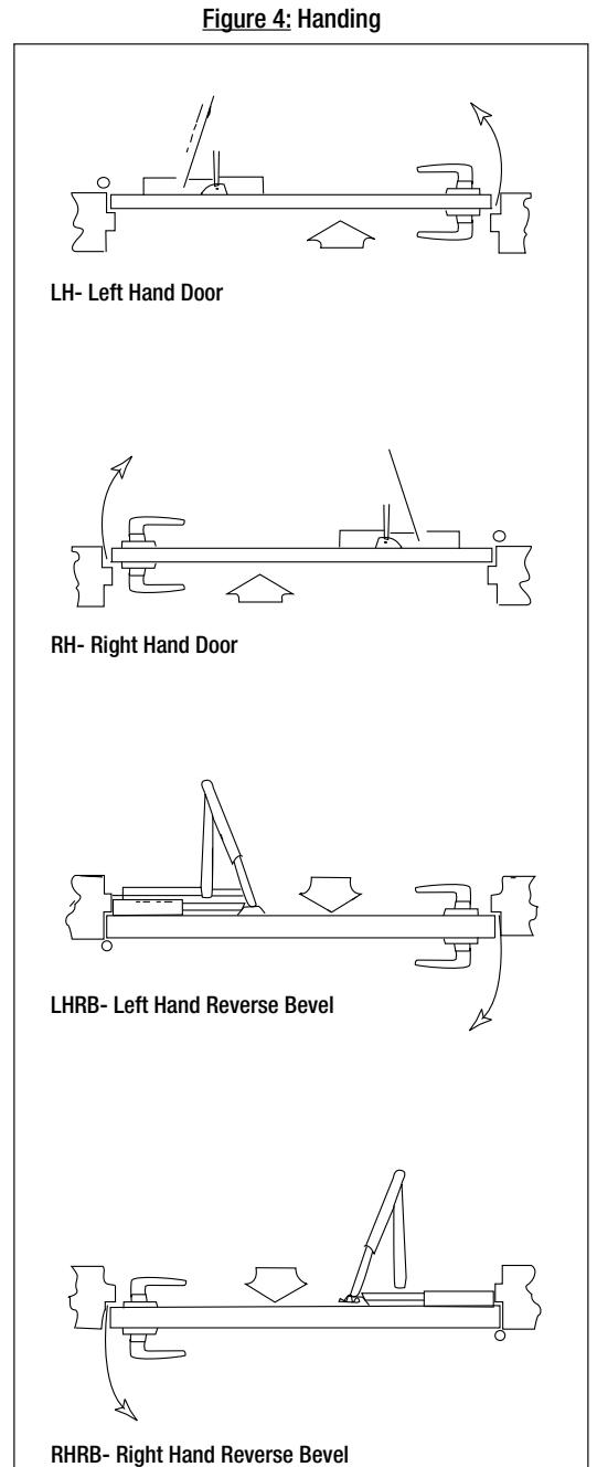
Figure 5: NB-WD7000 Assembly Exploded View
Top Bolt & Rod Assembly A
Outside Lever Trim
4
NB-WD7000 & 12-NB-WD7000 Series-Installation Instructions (Less Bottom Rod)- Continued
B) Installation
- 1. Measure gap between top of door & frame and bottom of door & floor before removing door from hinges. (See Steps 5-6).
- 2. Attach inner chassis (B) to door with (2) #10 x 1-1/4" Phillips flat head wood mounting screws (CC). (See Figure 5).
- 3. Screw top rod (A) into inner chassis (B) from top of door.
- 4. Place trim backplates between lever trim and door surfaces with unfinished side toward the door surface. Insert spindle thru 1-1/4" hole. Spindle cams must be UNDER inner chassis platform (C). Insert lever trim mounting screws, 1/4"-20 x 3", (BB) through trimplate and tighten.
- 5. Use inside trim to adjust top bolt and rod assembly (A).
- For 1/8" GAP OR LESS between top of door and door frame, rotate bolt even with top of door.
- For 1/8" GAP OR GREATER between top of door and door frame, rotate bolt to gap space minus 1/8" above door.
Inner Chassis
4 NB-WD7000 & 12-NB-WD7000 Series-Installation Instructions (Less Bottom Rod)- Continued
Figure 6: NB-WD7000 Assembly Exploded View
(4) #12-2" Flat Head Wood Screws- Top Chassis Mounting Screws
AA
E Top Chassis
Top Bolt & Rod Assembly A
Outside Lever Trim
B) Installation- Continued
- 6. Slide top chassis (E) over top bolt (A). Secure with (4) #12-2" flat head wood screws (AA). (See Figure 6).
- 7. Install door into the frame using hinges.
- 8. Attach 650 Top Strike to door frame, (2) #10-24 x 1/2" Phillips flat head machine screws (Reference template # 4449). (See below).
-
9. BEFORE CLOSING DOOR, ensure the following: (Adjust top bolt per Steps 5 as needed):
- a) Either lever retracts bolt.
- b) Bolt stays retracted (in hold back).
- c) Bolt releases when door closes; button inside top of door hits frame.
- d) Bolt engages strike, 1/4"- 5/16".
C) Strikeplate
650 Top Strikeplate
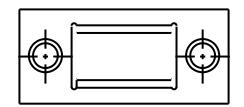
650 Top Strike, WD-NB7000 & 12-NB-WD-7000 Strike Pack

5 WD7000, 12-WD7000, NB-WD7000, & 12-NB-WD7000 Series CLASSROOM FUNCTION-Installation Instructions
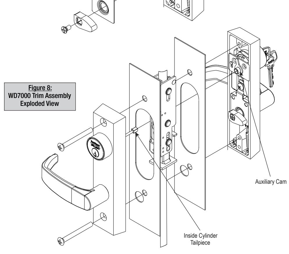
A) Installation 1. Through bolt the trim as described in Step 4 on Page 8. Ensure that the inside cylinder tailpiece engages the auxiliary cam on the outside trim. 2. Check for smooth locking and unlocking via cylinder on both sides of the door. 3. Remove components shown below in order to replace outside cylinder. 4. Reinstall removed components after cylinder is installed. Figure 7: WD7000 Trim Assembly Exploded View Figure 8:
Hardware Supplied:

Auxiliary Control Device
5 WD7000, 12-WD7000, NB-WD7000, & 12-NB-WD7000 Series CLASSROOM FUNCTION-Installation Instructions- Continued
B) WD100 Series Auxiliary Control Product Installation
- 1. Slide the extension, with reduced diameter facing down, through the cut out for the inner chassis on the door.
- 2. Insert inner chassis into the door cutout and insert reduced end of extension in top threaded bushing on inner chassis. Secure with (1) #8-32 x 7/16" Phillips oval head machine screw. (Only on aux control devices), (See Figure 9).
FOR AUXILIARY CONTROL:
3a. Install plate onto extension going from the outside of door through the cutout.
FOR ELR CONTROL:
- 3b. Install plate onto extension going from the inside of door through the cutout.
- 4. Attach inner chassis mounting plate to inner chassis assembly with (2) #10 x 1-1/4" flat head screws (CC).
- 5. Attach 100 Series Auxiliary Control to door with (2) #10-24 x 2-1/8" Phillips oval head machine screws (DD). (Only on aux control devices).
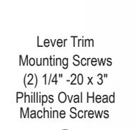
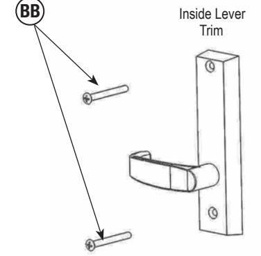
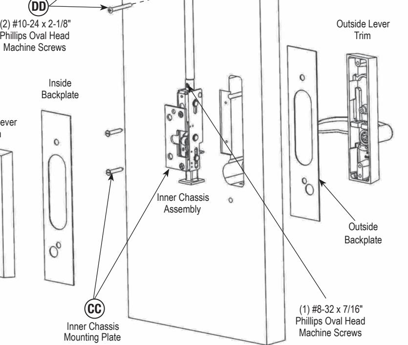
Figure 9: WD7000 Trim Assembly Exploded View
Extension
Plate
Copyright © 2015, Sargent Manufacturing Company, an ASSA ABLOY Group company. All rights reserved. Reproductions in whole or in part without express written permission of Sargent Manufacturing Company is prohibited.
(2) #10 x 1-1/4" Phillips Oval Head Machine Screws
7000 Concealed Vertical Rod Device

SARGENT Manufacturing 100 Sargent Drive New Haven, CT 06511 USA 800-727-5477 • www.sargentlock.com
Founded in the early 1800s, SARGENT® is a market leader in locksets, cylinders, door closers, exit devices, electro-mechanical products and access control systems for new construction, renovation, and replacement applications. The company's customer base includes commercial construction, institutional, and industrial markets.
Copyright © 2015, Sargent Manufacturing Company, an ASSA ABLOY Group company. All rights reserved. Reproduction in whole or in part without the express written permission of Sargent Manufacturing Company is prohibited.
ASSA ABLOY is the global leader in door opening solutions, dedicated to satisfying end-user needs for security, safety and convenience.