W53032 MR J Trim Instruction – Rev3
Open the original PDF document
View PDFMR – MORTISE LOCK ESCUTCHEON TRIM
INSTALLATION INSTRUCTION

1. DOOR PREPARATION
- Prepare the door for the mortise lock. Generic template in box, function specific templates located at www.pdqlocks.com
- Install the mortise case and secure using two (2) #12-24 combo screws supplied in the hardware kit, W51440.
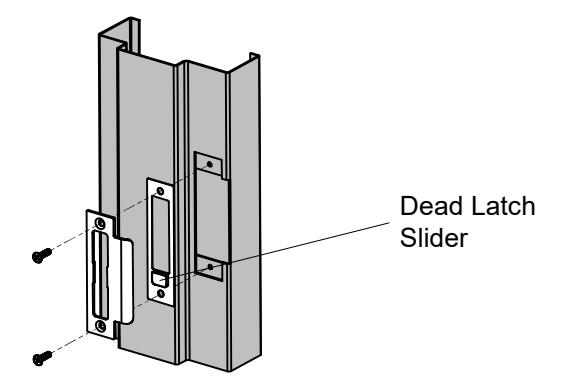
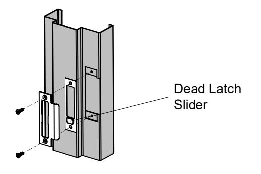
2. JAMB PREPARATION
- Prepare the jamb for the mortise lock strike.
- Install Dead Latch Plate behind strike with slider toward bottom for dead latch.
- Install the strike and secure with two (2) #12-24 combo screws supplied in the strike screw pack .
3. INSTALL CYLINDER
Thread cylinder into lock case. Do not secure cylinder, it will be tightened in Step #7.
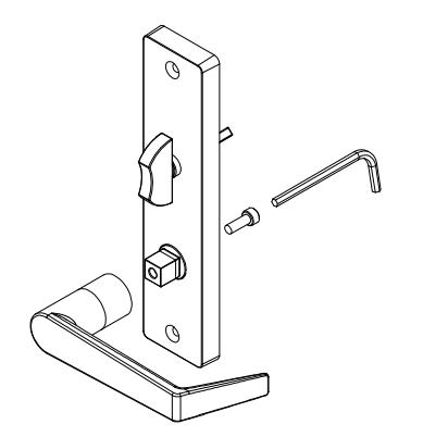
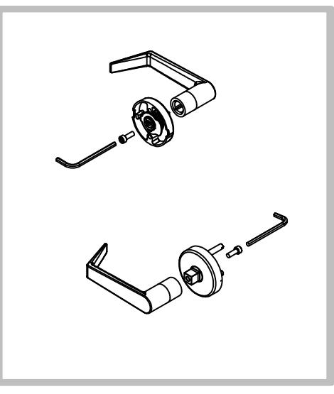
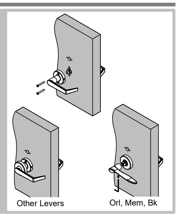
4. ATTACH LEVERS
- Attach levers using supplied hex key to tighten socket head cap screws supplied in hardware kit, W51440.
- Be sure to orient each lever for correct lock handing. Some lever styles are handed and will only work on the correct side of the lock.
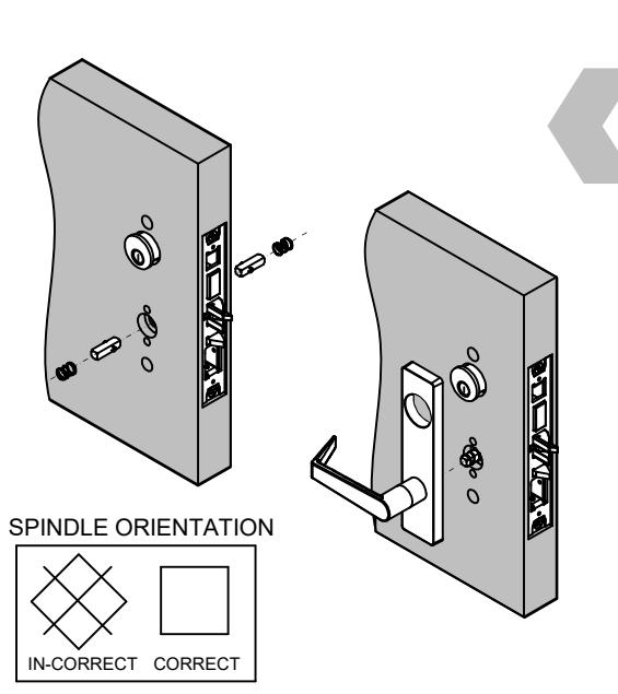
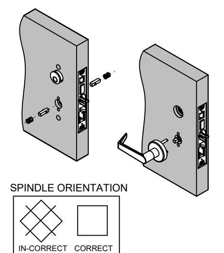
5. INSTALL SPINDLES / OUTSIDE TRIM
Drive Spindles:
Install spindles and springs on both sides in orientation shown.
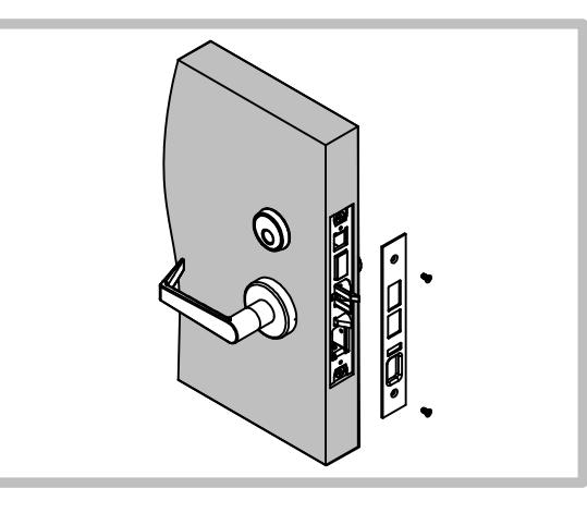
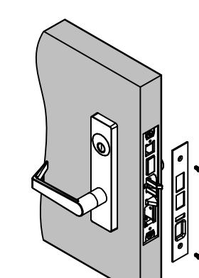
Outside Trim
- Install outside escutcheon to door while aligning lever with drive spindle.
- Confirm spindle engagement in lock by rotating the lever down and verifying that the latch retracts.
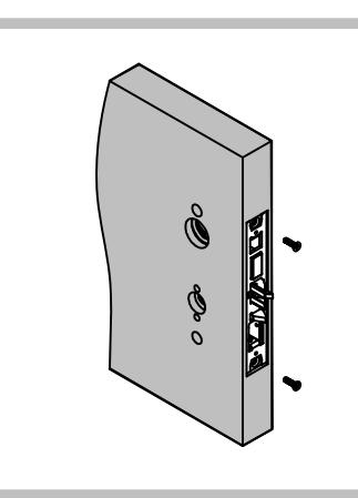
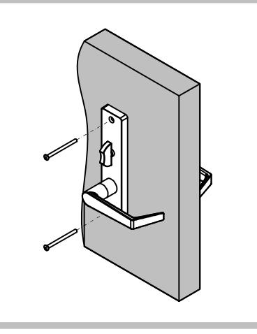
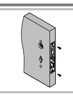
6. INSTALL INSIDE TRIM / SECURE TO DOOR
- Install inside escutcheon to door while aligning lever with drive spindle - confirm spindle engagement.
- Secure the escutcheon with two (2) #10-24 x 2-1/2" oval head machine screws, supplied in the Hardware Kit, W51440.
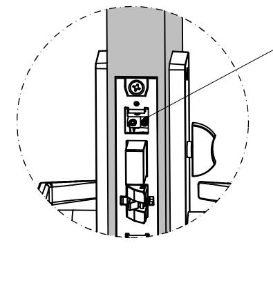
Cylinder Set Screw – Tighten side(s) with cylinder
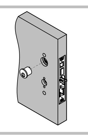
7. TIGHTEN CYLINDER / INSTALL ARMOR PLATE
-
Adjust the cylinder making it flush or slightly recessed into the escutcheon
- For I/C housings, install the slotted set screw through the I/C bore to secure the housing.
- Secure the cylinder by tightening the cylinder set screw through the front of the case with the supplied 2.5mm hex key. Does not apply to I/C when using slotted set screw.
- Install and secure the armor plate with two (2) #8-32 flat head screws.
MR – MORTISE LOCK SECTIONAL TRIM
INSTALLATION INSTRUCTION

1. DOOR PREPARATION
- Prepare the door for the mortise lock. Generic template in box, function specific templates located at www.pdqlocks.com
- Install the mortise case and secure using two (2) #12-24 combo screws supplied in the hardware kit, W51411.
2. JAMB PREPARATION
- Prepare the jamb for the mortise lock strike.
- Install Dead Latch Plate behind strike with slider toward bottom for dead latch.
- Install the strike and secure with two (2) #12-24 combo screws supplied in the strike screw pack .
3. LEVER ATTACHMENT
Assemble the outside rose as shown using the supplied 4mm hex key to tighten the M5x0.8x14mm socket head cap screw. Scalp should be installed on outside scalp before lever is attached.
Orlando/Memphis Levers & Ball Knob - Skip the following step. Do not install inside lever and discard one (1) M5x0.8x14mm socket head cap screw. Refer to step 5.
Assemble the inside rose as shown using the supplied 4mm hex key to tighten the M5x0.8x14mm socket head cap screw. Inside rose scalp should not be installed at this point.
4. INSTALL SPINDLES / OUTSIDE TRIM
Drive Spindles:
Install spindles and springs on both sides in orientation shown.
Outside Trim
- Install outside escutcheon to door while aligning lever with drive spindle.
- Confirm spindle engagement in lock by rotating the lever down and verifying that the latch retracts.
5. INSTALL INSIDE TRIM / ROSE
- Install the inside rose assembly to the inside of the door. Align the spindle with the lever.
- Secure inside rose assembly with #10-24x1-1/2" flat head machine screws, supplied in the hardware kit, W51411 - Confirm the spindle engagement.
- Install the rose scalp by aligning the dimples with the slots in the rose plate. Secure by rotating clockwise until tight.
FOR ORLANDO/MEMPHIS LEVERS & BALL KNOB
Slide lever onto spindle. Install M5x0.8 set screw in bottom of lever. Tighten from underside with supplied 2.5mm hex key.
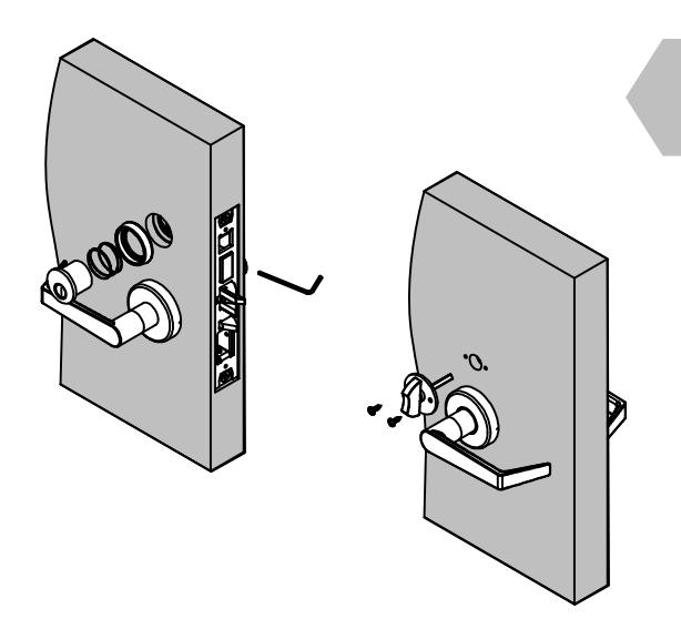
6. CYLINDER & TURNPIECE INSTALLATION
- Thread the cylinder into the lock body until the cylinder is flush or slightly recessed in the cylinder trim collar.
-
Secure the cylinder by tightening set screw through front of case, on the side of cylinder, with the 2.5mm hex key provided in the hardware kit, W51411.
- For I/C housings, install the slotted set screw through the I/C bore to secure the housing.
- Install the thumb turn and secure with two (2) stainless steel #6x1/2" truss head sheet metal screws, supplied in the thumb turn screw pack.
7. INSTALL ARMOR PLATE
Install the armor plate with two (2) stainless steel #8-32 x 1/4" flat head machine screws.