Von Duprin Auxiliary Hardware Catalog
Open the original PDF document
View PDF

Introduction
Flexible solutions for real-world applications
There's a reason why customers have trusted Von Duprin® to keep them safe for more than 100 years. From robust materials to flexible design, Von Duprin products are engineered with you in mind. Invest in a brand that is built to last.
Passion driving performance
Supported by industry-leading expertise, Von Duprin customers receive superior products and exceptional customer service. From fire and life safety codes to installation resources, Allegion's knowledgeable technical support representatives average more than 15 years of experience each. And for those looking to take their expertise to the next level, Allegion offers instructor-led workshops, videos and online courses. It's another way Von Duprin stands by its customers—today, tomorrow and for years to come.
Table of contents
|
ANSI Functions
for exit hardware |
5 |
|---|---|
| Cover plates / Dogging keys | 8-9 |
| Cylinders | 10 |
| Glass bead kits | 10 |
| Handing chart | 5 |
| Mullions | 12-13 |
| Sex bolt | 6 |
| Vertical rod/Latch guard | 10 |
| Two point latch | 11 |
| Weather stripping | 14 |
Symbols

About Von Duprin
The disastrous Iroquois Theater fire in Chicago happened in 1903. Carl Prinzler, Manager of the Vonnegut Hardware Company Builders Hardware Department, was scheduled to be at the matinee, featuring Eddie Foy, but other matters prevailed and he was spared. Five hundred ninety people died, mainly because the theater doors opened inward.
Prinzler spent the next five years working with Henry Dupont, an architectural engineer, developing hardware to preclude a similar horror. Together they fashioned a lever that kept doors locked on the outside, yet unlocked from the inside. The pivotal element was the crossbar which opened the door outward once any part of the body touched it.
That was 1908. Since that time, Von Duprin has been instrumental in transforming fire and panic exit hardware into sleek, attractive products available in a wide range of styles, functions and finishes.
Thorough and continuous research by Von Duprin has resulted in a parade of improvements and enhancements that has earned it the reputation of being the "R & D Department for the entire industry."
- Von Duprin was first to use drop forgings.
- Von Duprin was first with a special threshold, the Latch-Track.
- Von Duprin developed the first reversible exit device, the 88 rim type device.
- Von Duprin introduced the first extruded aluminum mullion.
- Von Duprin was first to market a concealed vertical rod device for metal doors.
- Von Duprin was first to market a concealed vertical rod device for wood doors.
- Von Duprin was the first to have a line of narrow stile devices, the type NC.
- Von Duprin produced the first stainless steel line of devices, the type 66 series.
- Von Duprin was the first with a line of pushpad devices, the type 33 series.
- Von Duprin was the first with electric locking and unlocking, the type E device.
- Von Duprin was the first with self contained delayed exit, CHEXIT®
In addition, during the 1920's Von Duprin developed the type Q
device, which was approved by Underwriter's Laboratories, Inc., for three hour fire rated doors. Subsequently, Von Duprin has successfully tested the industry's most complete line of Fire Exit Hardware.
Along with these impressive developments, we are proud of our record of manufacturing quality products that give years and years of solid dependable service with minimum maintenance. While it is satisfying to reflect on these accomplishments, it is even more significant that Von Duprin has the purpose and the spirit to continue to lead the fire and life safety industry in providing "THE SAFE WAY OUT!"
How the name "VON DUPRIN" originated: VON (Vonnegut Hardware Company), DU (DuPont), the architectural engineer, who helped PRIN (Prinzler) develop the first Von Duprin exit device.
UL listings
Most Von Duprin exit devices are UL Listed for Panic Hardware or Fire Exit Hardware, and are tested in accordance to ANSI A156.3, 2008, Grade 1.
UL listed panic hardware
To be UL listed a device must pass rigorous tests to prove it is mechanically sound and reliable. One test puts the device through 100,000 controlled open and close cycles. In another, the activating mechanism is required to operate with 50 pounds of pressure or less when 250 pounds of pressure is applied to the door in the direction of the swing.
Fire exit hardware
To carry the UL Label for Fire Exit Hardware, a device first must meet the Accident Hazard requirements. Secondly, the device must pass the burn test to prove that it can hold fire doors closed for up to a three hour period in temperatures over 1900°F. Immediately after burning, a fire hose with approximately 45 lbs. PSI pressure at the nozzle puts stress on the opening as a final test of the hardware's ability to hold the doors closed.
ANSI Functions for exit hardware
A variety of ANSI functions are offered with each series. Each device section of the catalog contains a chart showing the ANSI types and functions available in the series.
| Function | |
|---|---|
| 01 | Exit only, no trim |
| 02 | Entrance by trim when actuating bar is locked down. |
| 03 |
Entrance by trim when latch bolt is retracted
by key. Key removable only when locked. |
| 04 | Entrance by trim when latch bolt is retracted by key or set in a retracted position by key. |
| 05 | Entrance by thumbpiece. Key locks or unlocks thumbpiece. |
| 06 | Entrance by thumbpiece only when released by key. Key removable only when locked. |
| 07 | Entrance by thumbpiece. Inside key locks or unlocks thumbpiece. Outside key retracts latch. |
| 08 | Entrance by knob or lever. Key locks or unlocks knob. |
| 09 | Entrance by knob or lever only when released by key. Key removable only when locked. |
| 10 | Entrance by knob or lever. Inside key locks or unlocks knob. Outside key retracts latch. |
| 11 | Entrance by control turn piece. Key locks or unlocks control. |
| 12 | Entrance by control turn piece only released by turning key. Key removable only when locked. |
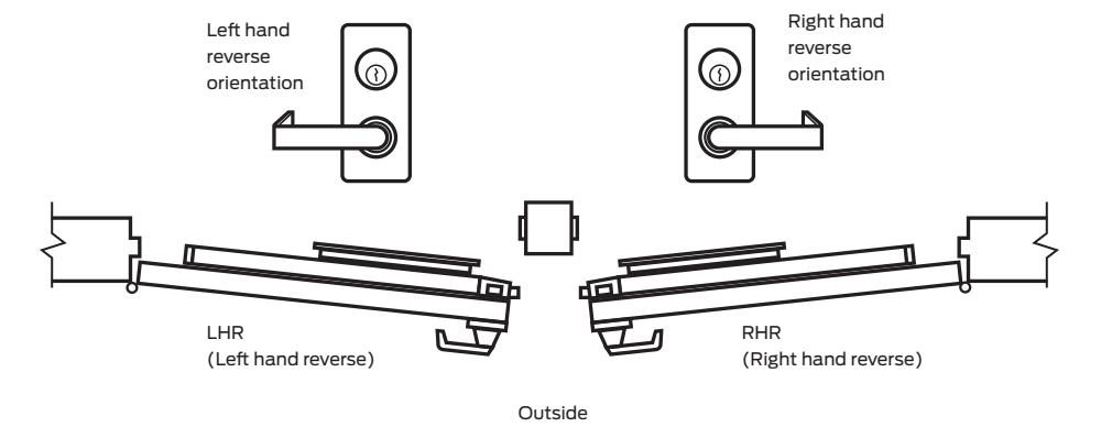
Door handing
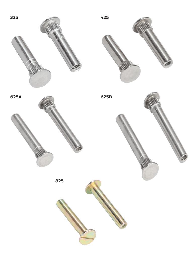
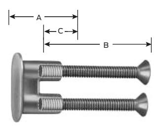
Sex bolts
Sex Bolts when ordered with devices may be furnished with screw lengths different than shown in Column B. On page 7, Column B indicates popular sizes. Sex Bolts ordered separately are not furnished with screws. If screws are required refer to chart on page 7 and order screws by description as a separate item. Other screw lengths may be used based on minimum and maximum allowable thread engagement, shown in column "C." Quantity required — refer to device section, quantities differ depending on outside trim.
425 sex bolts are required for 22/88/98/99 series fire rated devices when used on wood door applications. When wood doors are specified for these devices, sex bolts will be added to the device application unless SLM blocking package is specified.
825 sex bolts are required with 98-F/99-F rim devices on wood door applications using EO, NL, TP, K and L outside trims. Two 825 sex bolts will be added to the device application unless SLM blocking package is specified.
To order, specify
- 1. Model number
- 2. Quantity (2 per package)
- 3. Finish
- 4. Door thickness other than 13 /4"(44mm).
Refer to page 7 for A, B and C lengths
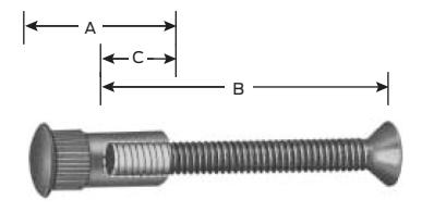
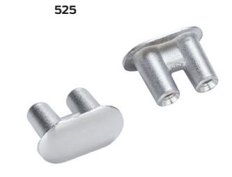
325,425,625A & 625B
Vertical rods
Rim, mortise and concealed vertical rod
| Cente | er case | Hinge case | |||||||||
|---|---|---|---|---|---|---|---|---|---|---|---|
| _ | Sex B | olt | C Thread | Sex b | olt | C Thread | |||||
| Device type |
Door
thickness |
No. A | B Screw |
engagement
min max. |
No. | Α | B Screw |
engagement
min. – max. |
|||
| 22 | 1³/₄" (44mm) | 425 | 1 9/16" | 10-24 x 1" PPHMS | 9/32" - 5/8" | 425 | 1 9/16" | 10-24 x 3 / 4 " PPHMS | 9/32" - 5/8" | ||
| 22 | 2¹/₄" (57mm) | 425 | 19/16" 10-24 x 11/2" PPHM | 9/32" - 5/8" | 425 | 19/16" | 10-24 x 1 1/4" PPHMS | 9/32" - 5/8" | |||
| 33A, 3347A, 3347A-F | 47A, 3347A-F 1 3/4" (44mm) 325 1 9/32" 1/4-20 x 1" FPHMS | 3/8" - 11/16" | 425 1 9/16" | 10-24 x 3 / 4 " PPHMS | 9/32" - 5/8" | ||||||
| 35A, 3547A, 3547A-F | 21/4" (57mm) | 325 | 1 9/32" | 1/4-20 x 1 1/2" FPHMS | 3/8" - 11/16" | 425 | 19/16" | 10-24 x 1 1/4" PPHMS | 9/32" - 5/8" | ||
| 1³/₄" (44mm) | 625A | 2 5/16" | 12-24 x 3 / 4 " OPHMS | 11 / 32 " - 13 / 16 " | 625A | 2 5/16" | 12-24 x 3 / 4 " OPHMS | 9/32" - 13/16" | |||
| 55 | 21/4" (57mm) | 625B | 2 13/16" | 12-24 x 3 / 4 " OPHMS | 11/32" - ]" | 625B | 2 13/16" | 12-24 x 1 1/4" OPHMS | 11/ 32 " - ]" | ||
| 5575, 5575-F | 1³/₄" (44mm) | _ | _ | 625A | 2 5/16" | 12-24 x 3 / 4 " OPHMS | 11/ 32 " - 13/ 16 " | ||||
| 5547, 5547F | 2 1 / 4 " (57mm) | _ | _ | _ | _ | 625B | 2 13/16" | 12-24 x 1 1/4" OPHMS | 11/ 32 " - 1" | ||
| 88, 88-F, 8875, | 1³/₄" (44mm) | 425 | 1 9/16" | 10-24 x 1 1 / 2 " OPHMS | 9/32" - 5/8" | 425 | 19/16" | 10-24 x 1 1 / 2 " OPHMS | 9/ 32 " - 5/ 8 " | ||
| 8875-F | 21/4" (57mm) | 425 | 19/16" | 10-24 x 2" OPHMS | 9/32" - 5/8" | 425 | 19/16" | 10-24 x 2" OPHMS | 9/32" - 5/8" | ||
| 8847-F | 1³/₄" (44mm) | _ | _ | _ | _ | 425 | 19/16" | 10-24 x 1 ½" OPHMS | 9/32" - 5/8" | ||
| 804/-F | 21/4" (57mm) | _ | _ | _ | _ | 425 | 19/16" | 10-24 x 2" OPHMS | 9/32" - 5/8" | ||
|
98, 9875, 9875-F,
9847, 9847-F, |
1³/₄" (44mm) | 425 | 1 9/16" | 10-24 x 1" PPHMS | 9/32" - 5/8" | 425 | 1 9/16" | 10-24 x 1" PPHMS | 9/32" - 5/8" | ||
|
99, 9975, 9975-F,
9947, 9947-F |
2 1 / 4 " (57mm) | 425 1°/16" 10-24 x 1 ½" PPHMS | 9/32" - 5/8" | 425 | 1 9/16" | 10-24 x 1 ½" PPHMS | 9/32" - 5/8" | ||||
| 98-F, 99-F* | 1³/₄" (44mm) |
425
825A* |
] 9/
16
"
] 13 / 16 " |
10-24 x 1" PPHMS
10-24 x 3 / 4 " PPHMS |
9/
32
" - 5/
8
"
9/ 32 " - 5/ 8 " |
425 | ] 9 / 16 " | 10-24 x 3 / 4 " PPHMS | 9/32" - 5/8" | ||
| 2 1 / 4 " (57mm) |
425
825B* |
1 9/ 16 " |
10-24 x 1
1
/
2
" PPHMS
10-24 x 3 / 4 " PPHMS |
9/
32
" - 5/
8
"
9/ 32 " - 5/ 8 " |
425 | ] 9 / 16 " | 10-24 x 1 1/4" PPHMS | 9/32" - 5/8" | |||
Surface vertical rod
| Center case | Hinge case | Top & bottom latch case | |||||||||||||
|---|---|---|---|---|---|---|---|---|---|---|---|---|---|---|---|
|
Device
type |
Door
thickness |
Sex bolt | C Thread | Sex bolt | C Thread | Sex bolt | C Thread | ||||||||
| No. | Α | B Screw |
engagement
min max. |
No. | Α | B Screw |
engagement
min. – max. |
No. | Α | B Screw |
engagement
min. – max. |
||||
| 2227, | 13/4" (44mm) | 425 | 19/16" | 10-24 x 1" PPHMS | 9/32" - 5/8" | 425 | 19/16" | 10-24 x 3 / 4 " PPHMS | 9/32" - 5/8" | 325 | 19/32" | 1/4-20 x 3/4" UFPHMS | 3/8" - 11/16" | ||
| 2227-F | 2½" (57mm) | 425 | 19/16" | 10-24 x 1 1/2" PPHMS | 9/32" - 5/8" | 425 | 1 9/16" | 10-24 x 1 1/4" PPHMS | 9/32" - 5/8" | 325 | 19/32" | 1/4-20 x 1 1/4" UFPHMS | 3/8" - 11/16" | ||
|
3327A
3527A |
13/4" (44mm) | 325 | 19/32" | 1/4-20 x 1" FPHMS | 3/8" - 11/16" | 425 | 19/16" | 10-24 x 3 / 4 " PPHMS | 9/32" - 5/8" | 325 | 19/32" | 1/4-20 x 3/4" UFPHMS | 3/8" - 11/16" | ||
| 2½" (57mm) | 325 | 19/32" | 1/4-20 x 1 1/2" FPHMS | 3/8" = 11/16" | 425 | 1 9/16" | 10-24 x 1 1/4" PPHMS | 9/32" - 5/8" | 325 | 19/32" | 1/4-20 x 1 1/4" UFPHMS | 3/8" - 11/16" | |||
|
8827,
8827-F |
13/4" (44mm) | 425 | 19/16" | 10-24 x 1 1/2" OPHMS | 9/32" - 5/8" | 425 | 19/16" | 10-24 x 1 ½" OPHMS | 9/32" - 5/8" | 425 | 19/32" | 10-24 x 3 / 4 " PPHMS | 9/32" - 5/8" | ||
| 21/4" (57mm) | 425 | 19/16" | 10-24 x 2" OPHMS | 9/32" - 5/8" | 425 | 1 9/16" | 10-24 x 2" OPHMS | 9/32" - 5/8" | 425 | 19/32" | 10-24 x 1 1/4" PPHMS | 9/32" - 5/8" | |||
|
9827,
9827-F 9857 9857-F |
l³/₄" (44mm) | 425 | 19/16" | 10-24 x 1" PPHMS | 9/32" - 5/8" | 425 | 19/16" | 10-24 x 3 / 4 " PPHMS | 9/32" - 5/8" | 325 | 19/32" | ³/₄-20 x ³/₄" UFPHMS | 3 / 8 " - 11 / 16 " | ||
|
9927,
9927-F 9897 9957-F |
2 1 / 4 " (57mm) | 425 | 19/16" | 10-24 x 1 ½" PPHMS | 9/32" - 5/8" | 425 | 1 9/16" | 10-24 x 1 1/4" PPHMS | 9/32" - 5/8" | 325 | ] 9/32" | ¹/₄-20 x 1 ¹/₄" UFPHMS | 3/8" = 11/16" | ||
FPHMS — Flat Phillips head machine screw OPHMS — Oval Phillips head machine screw PPHMS — Pan Phillips head machine screw UFPHMS — Undercut flat Phillips head machine screw)
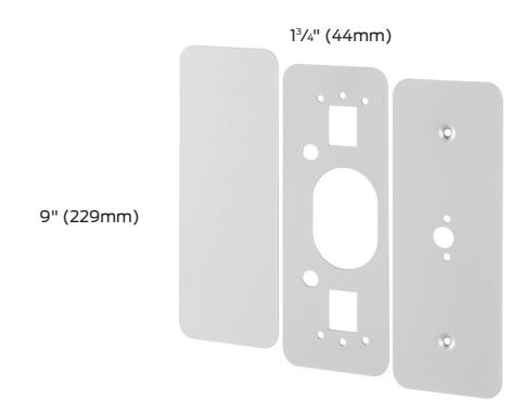
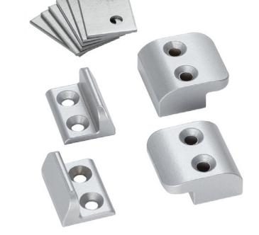
Cover plates
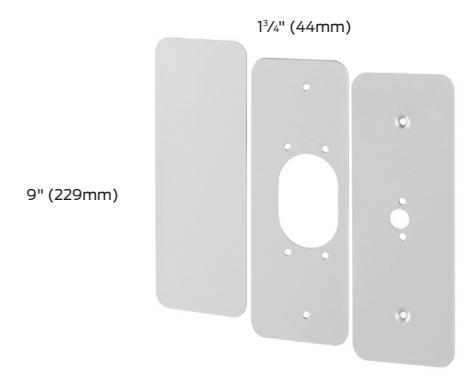
229 Kit
(For 22 Rim device)
Kit contains inside and outside plates for hinge stile cutouts, an inside plate for the the lock stile, and necessary screws. Plates are designed to cover cutouts required by most existing exit device installations. Specify finish.
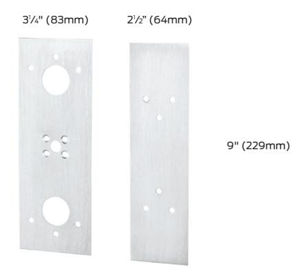
882 Kit
(For 88 Rim device)
For use to cover mortise lock or discontinued device cut-outs. Specify finish.
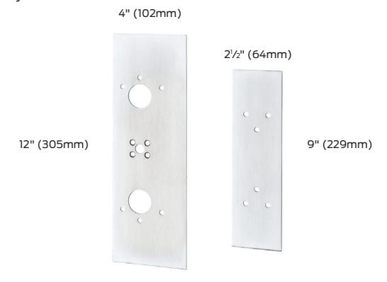
997 Kit
(For 98/99 Rim Device)
Kit contains inside and outside plates for hinge stile cutouts, an inside plate for lock stile, and necessary screws. Plates are designed to cover cutouts required by most existing exit device installations. Specify finish.
887 Kit
(For 88 Rim/8827 Devices)
For use with rim/vertical device combinations on pairs of doors with ANSI cut-out. The 88 rim device backset is increased and exposes the 161 cutout when used with an 8827. Specify finish
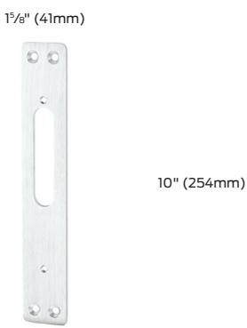
589 Kit
(For 5575 Device)
Kit contains plates for the lock stile and hinge side of the device, and necessary screws. Plates are designed to mount to device on wood door applications. The mortise lock cut-out interferes with device mounting. Specify finish and door width other than 1 /4" (44mm).
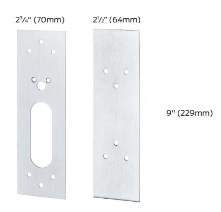
888 Kit
(For 8875 or 8827 Devices)
For use on doors with ANSI 161 cutouts. Device center case will not cover stock cutout. Specify finish.
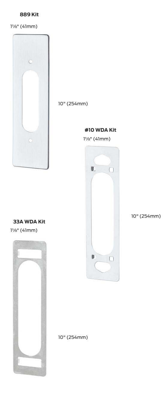
Cover plates
889 Kit
(For 373L Control)
Required when 373L controls are used with sex bolts. Four studs on cover plate allow through bolting to the device center case Note: Sex bolts must be used on wood or composite fire doors. Specify device type R, M, or V and finish.
998 Kit
(For 994L Trim)
For use with 994 lever trim to cover existing 992 lever trim cut-out. Specify finish
#10 WDA Kit
(For 370 Series controls)
For wood door applications, used to cover up door preparations for control, also prevents the control from boring into the wood door. Finished to match control.
33A WDA Kit
(For 360 Series controls)
For wood door applications to cover up door preparations for control, also prevents the control from boring into the wood door Finished to match control.
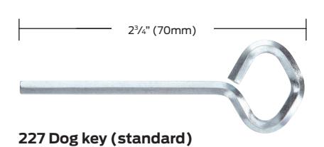
Dog keys
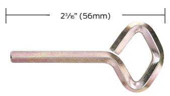
222 Dog key (old style)
/32" (4mm) hex
/32" (4mm) hex
Cylinders
Cylinders
Cylinders are not furnished with device or trim and must be specified when ordering. Refer to exit device catalogs for cylinder requirements.
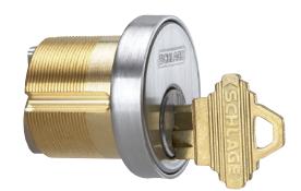
Mortise — 3215 (Schlage 20-001, B502-191 cam)
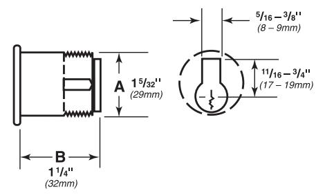
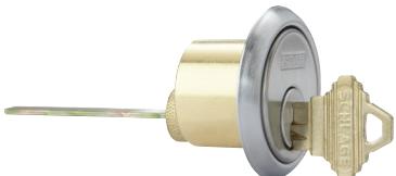
Rim — 3216 (Schlage 20-022 cam)
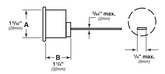
3218 Dummy
Glass bead kit – GBK
Glass bead conversion kits are used on doors with glass beads. Each kit consists of 11 /4" (6mm) shim sets. GBK for Surface Vertical Rod ships with 11 /8" (3mm) shims for rod guides. Shims are not required for top and bottom latches
To order, specify:
- 1. Device Model. Example: 99GBK
- 2. Device type (rim, mortise, surface vertical rod, concealed vertical rod)
- 3. Wood door, when used with concealed vertical rod
- 4. Specify if using with 499F Strike
- 5. Finish
RG-27 Vertical rod and latch guard
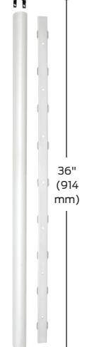
Rod guard
RG-27 Series vertical rod and latch guards protect the bottom rods of exit devices from the damaging impacts of carts or gurneys passing through doors. (If bottom rods become damaged, the exit device will not function as intended and can jeopardize the ability to exit safely during an emergency.)
In addition to protecting the vertical rod, the guard provides a smooth, unobstructed surface so the door can be pushed open easily with the bumpers of a wheelchair. The latch guard portion is 10" high. The standard latch guard features a 45° ramp. The extended latch guard offers a continuous ramp in 3' or 4' widths.
All stainless steel construction in US32D finish. Latch guards can cover latches as large as 1 1 /4"W x 10"H x 1 7/8" projection.
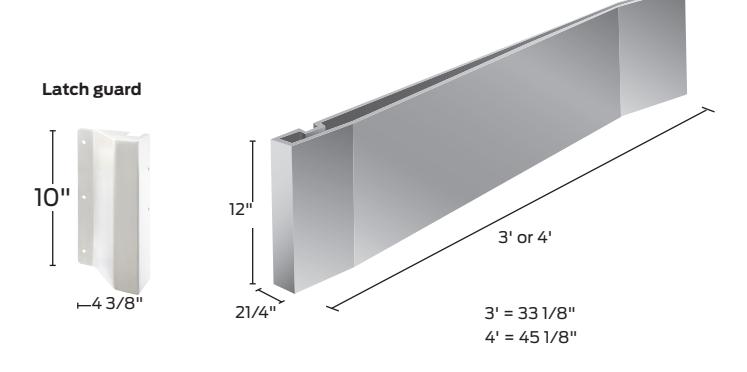
Models
RGO Rod guard only (Projection 1 3/16")
RG-27 Rod and latch guard
RG-27-3 3' (914 mm) Rod guard and extended
latch guard
RG-27-4 4' (1219 mm) Rod guard and extended
latch guard
LGO Latch guard only
LGO-3 3' (914 mm) Extended latch guard only
LGO-4 4' (1219 mm) Extended latch guard only
Note: Not for use on wood fire doors, except with SLM (special laminate material) blocking.
To order, specify:
- 1. Model number.
- 2. Handing (except on RGO).
- 3. Door material if other than Hollow Metal.
- 4. Optional sex bolt mounting available.
237 Two point latch

Series 237 Two point latch
Series 237 Two point latch assembly is ideal for spaces where occupancy does not require panic or fire exit hardware. This product is a perfect solution for many applications in schools, health care facilities, offices, and government facilities regardless if the doors are inswing or outswing. It can be used on the inactive leaf of a pair of doors with a lockset or both leaves of a pair. It features a top soffit latch and ratchet release for long service life and dependability. Locking handles in many different configurations provide versatility to meet different customer needs.
Engineered to withstand severe weather conditions, the 237 series is also ideal for community shelters and safe rooms in accordance with FEMA 320 and 361 guidelines.

I. UL listings:
Two- and Three-point Locks and Latches ( for use on Fire Doors) — UL 10 C
- Rating: 3HR Pairs (Double Egress)
- 90 Min. Pairs (Swing Same Direction)
- Door Size: 8'0" X 8'0" Pairs (Hollow Metal Only)
-
II. Windstorm ratings:
-
A. UL FEMA 320 and 361 certified:
- i. 4'0" X 8'0" Single Doors (Non-fire-rated) Hollow Metal
- ii. 8'0" X 8'0" Pairs Hollow Metal
- B. UL–ANSI/ICC 500 certified for F5 Tornado applications
-
A. UL FEMA 320 and 361 certified:
These products are listed with Steelcraft PW14 Series door for Tornado Listings
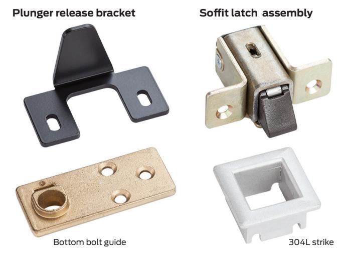
Furnished standard with one lever control assembly with mounting plate for the push side. This lever operation is always unlocked (L-BE). A second control lever can be ordered separately for the pull side, either model 378L-BE (always unlocked) or model 378L (with cylinder locking). Cylinders not included.
Lever operation meets all ADA requirements.
To order, specify:
- 1. Model number 237L-BE.
- 2. Optional second control, 378L or 378L-BE.
- 3. Handing (see charts below).
- 4. Finish.
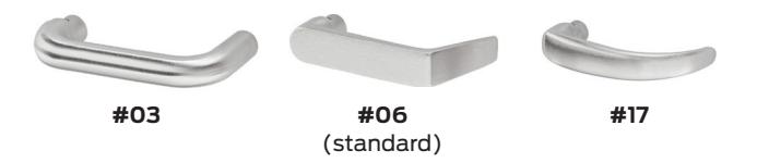
Optional lever styles are available
Handing – how to order
Outswing door application
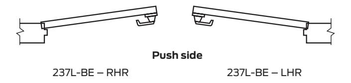
NOTE: For inswing door applications that require locking on the push side, consult factory. Outswing door will be assumed if not specified.
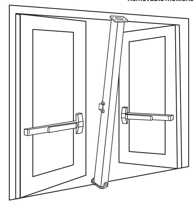
Mullions
Mullions
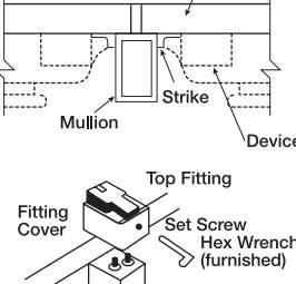
Removable steel mullions Mullions provide single door performance in double door openings with rim devices. Mullions are easily removed by loosening bottom set screw and removing top fitting cover. The top mullion fitting is attached to the frame and is concealed by the fitting cover.
Steel mullions are 2" (51mm) wide and 3" (76mm) deep, with a wall thickness of 1 /8" (3mm).
Mullions are shipped with mounting screws and prepared for strikes. Strikes are not included except where indicated.
Steel mullions are available in SP28 and SP313 finishes. Consult factory for other powder coat finish options.
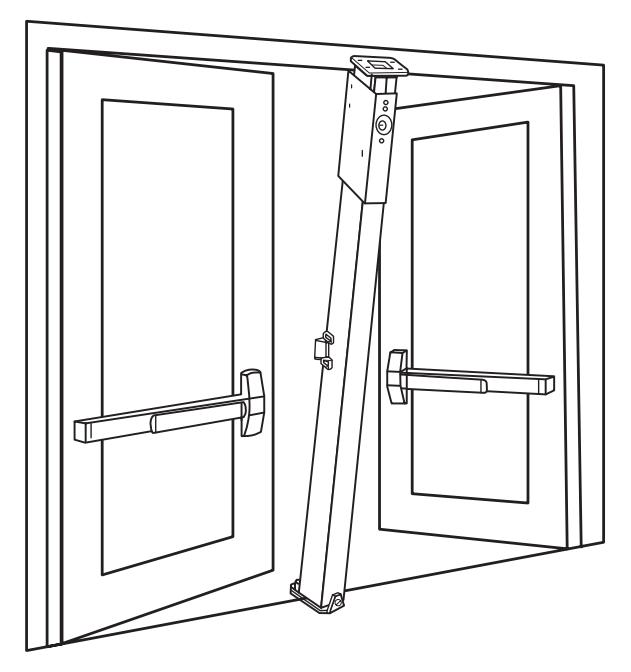
KR – Keyed removable steel mullions makes removal faster and easier by a single operation of the mortise cylinder. Once mullion is removed, large equipment or furniture can freely pass through the opening. The unit will self lock when re-installed, without use of the cylinder key. Uses a 11 /4" mortise cylinder with a straight cam (Schlage cam reference B502-191). Cylinders are sold separately. Prefix mullion model with "KR".
Removeable aluminum mullions are 11 /16" (27mm) wide on face closest to the door and 23 /8" (60mm) at the widest point. The depth is 31 /8" (79mm) with a wall thickness of 1 /8" (3mm).
Aluminum mullions are available in US4, US10, US28, 313 and 315 finishes. Consult factory for other powder coat finish options.
Stock Hollow Metal Applications for devices mounted to cover ANSI 161 cutouts are higher than the standard mullion strike location. Consult the factory for special strike preparation or order a blank mullion. See below.
Blank Mullions are furnished without strike preparation. They are used to mount devices at a strike height different from the standard mullion preparation.
To order, specify:
- 1. For keyed Removable option on steel mullions, prefix model number with "KR"
- 2. Model number.
- 3. Height of opening
- 4. Finish
- 5. Handing if required.
- 6. Centerline deviation (refer to device template for standard centerline).
- 7. Strikes, when required, should be ordered with device.
- 8. For keyed Removable option on steel mullions, prefix model number with "KR"
Removable mullions
Keyed removable steel mullions
Mullions
Steel mullions
1654 Prepared for two 1606 strikes. If 1606 strikes are not specified on the order, two per mullion will be added. Additional charges apply.
4954 Prepared for 264 or 299 strikes. For use with all Von Duprin Panic rim devices. Note: specify strike choice with device.
9954 Prepared for and must be used with two 268 strikes (88-F device), or two 499F (22-F, 98-F, 99F devices). UL fire labeled mullion for up to 3 hour opening using Von Duprin fire exit rim devices. This mullion is not
easily removed due to special fittings.
22-F and 88-F devices are rated up to 8' x 8" (2438mm x 2438mm).
98-F and 99-F devices are rated up to 10'0" (3048mm).
Note: If 268 or 499F strikes are not specified on the order, two per mullion will be added. Additional charges apply.
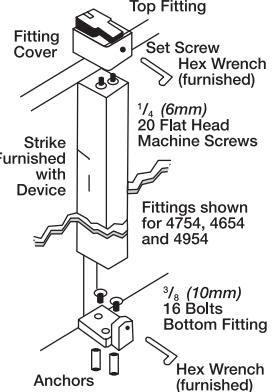
- 4754 Prepared for two 4263 monitor strikes.
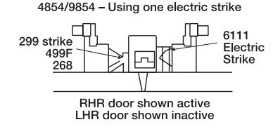
- 4854 Prepared for one 299 and one 6111 electric strike. Indicate handing for electric strike.
- 9854 Prepared for one 268 or 499F strike and one 6111 electric strike. Indicate handing for electric strike. UL fire labelled mullion for up to 3 hour openings up to 8' x 8' (2438mm x 2438mm) using Von Duprin Fire Exit Rim Devices
Aluminum mullions
5654 Prepared for two 264 or 299 strikes with weatherstripping. Includes one set of 154 stabilizers.
5754 Prepared and furnished with one 1408 double door strike. Includes one 154 stabilizer set. Note: specify device "less strike".
Sizes for mullions
1654, 4954, 4754, 4854, 5654 9854, 9954 7' 2" (2184mm) 7' 3" (2210mm) *8' 2" (2489mm) 8' 3" (2475mm) *10' 2" (3099mm) 10' 3" (3124mm)
KR1654, KR4954, KR4754, KR4854 KR9854**, KR9954***
7' 6" (2286mm) 7' 5" (2261mm) 8' 6" (2591mm) *8' 5" (2565mm) 10' 6" (3200mm) *10' 5" (3175mm)
- * Only qualifying applications will be provided with UL Label.
- ** Fire rated same as 9854
- *** Fire rated same as 9954
and mullion.
Angle plate is used with narrow transom frames. The plate attaches to the transom extending the surface area needed to mount the mullion. Must be ordered separately. Specify finish.
154 Stabilizer is a two-piece interlocking set. One piece mounts on the mullion with the top mounting hole 53 /16" (148mm) below the centerline of the strike; the other piece mounts on the door. Shims are provided to adjust for misalignment between the door
The set maintains integrity between the door and mullion to prevent vandalism and to ensure contact between the device and strike as the doors expand and contract with temperature changes.
Furnished standard on aluminum mullions; optional for steel and all blank steel mullions.
MT54 Storage kit is a set of floor and wall brackets that provide convenient storage of the keyed removable mullion when removed from the opening.
To order, specify
- 1. Model MT54.
- 2. Finish SP28, SP313, or SPBLK
Weatherstripping
Weatherstripping
Weatherstripping prevents cold air from blowing between doors and mullion. It also serves as a silencer when the door is closed against the mullion. The silicone treated weatherstrip pile is bonded to a polypropylene backing. A slide-in molding houses the weatherstripping, covers mounting screws of the strike and extends to both the top and bottom of the mullion. Available on aluminum mullions only.
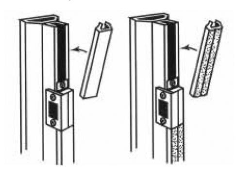
Standard edging
Edging with weatherstripping
About Allegion
Allegion (NYSE: ALLE) is a global pioneer in safety and security, with leading brands like CISA®, Interflex®, LCN®, Schlage®, SimonsVoss® and Von Duprin®. Focusing on security around the door and adjacent areas, Allegion produces a range of solutions for homes, businesses, schools and other institutions. Allegion is a $2 billion company, with products sold in almost 130 countries.
For more, visit www.allegion.com