Valuewave CM-221 Maniual
Open the original PDF document
View PDF

Door Activation Devices
CM-221
Touchless Exit Switch with Remote LED Triggering
INSTALLATION INSTRUCTIONS
PARTS INCLUDED IN THE BOX
- (1) CM-221
- (1) Parts bag (Contents: (2) 6-32 X 1/2" oval head Phillips ss screws, (2) 6-32 X 1/2" snake eye s/s flat head screws, (1) Key for tamper proof screws (snake eye), (1) Jumper for factory external LED control)
- (1) User/Installation Manual
- (1) Faceplate Gasket
1. GENERAL DESCRIPTION
The CM-221 Hands-Free Switch uses active infra-red microburst sensor technology, designed for use in ADA compliant automatic door control applications and access control.
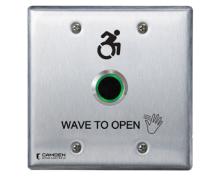
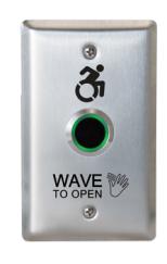
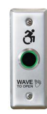
The CM-221 switches eliminate the spread of germs by avoiding physical contact, and provide greater convenience when moving through the premises. The switches are available with stainless steel faceplates, in narrow (jamb), single gang or double gang configurations.
All models are ROHS compliant with lead-free construction. Built-in remote LED switching allows for integration with third-party applications, such as guard and nurse station annunciators. Adjustable time delay from 0.5 to 20 seconds and an adjustable range from (2" to 8" / 5cm to 20cm).
2. SPECIFICATIONS
| Voltage | 12 to 24 VDC +/- 10% |
|---|---|
| Current | 45 mA (peak) |
| Contact Rating | 1 Amp @ 30 VDC |
| Contacts | Common/ N.O./ N.C. |
| Temperature Range | 14F to 122F (-10 to 50 °C) |
| Response Time | 10ms |
NOTE: Do NOT use AC Voltage for this unit. Please see section 8 for power requirements
|
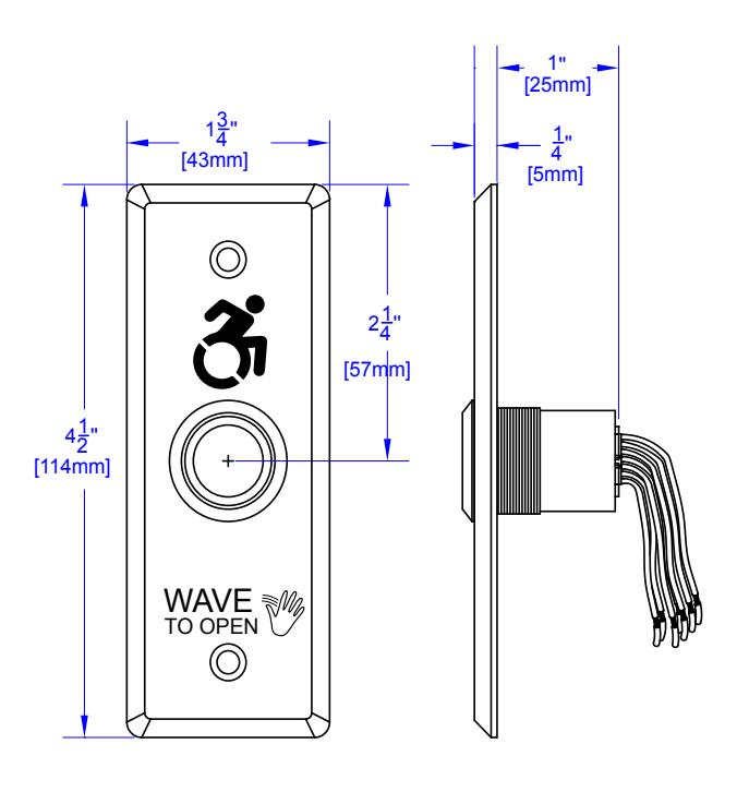
Narrow:
1 3/4" W x 4 1/2" H x 1 1/4" D (43 mm x 114 mm x 31 mm) |
|
|---|---|
| Dimensions |
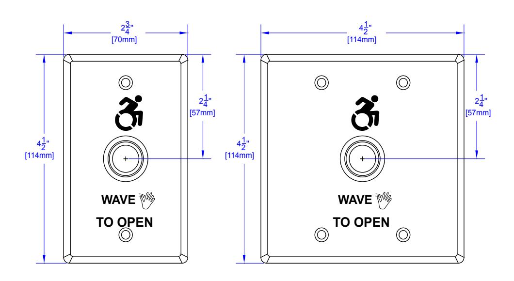
Single Gang:
2 3/4" W x 4 1/2" H x 1 1/4" D (70 mm x 114 mm x 31 mm) |
|
Double Gang:
4 1/2" W x 4 1/2" H x 1 1/4" D (114 mm x 114 mm x 31 mm) |
3. FEATURES
- Built-in Red and Green LED indication. Factory default = Red (Standby), Green (Triggered)
- Red and Green LEDs can be controlled by sensor or externally
- Adjustable detecting distance: 2 to 8 Inches (5 cm to 20 cm)
- Adjustable Time Delay: 0.5 seconds to 20 seconds
- Toggle function selection available
- IP65 rating
- IR lens to provide stable and reliable operation
4. OPERATION AT A GLANCE
In a typical application, as you approach the CM-221, the LED will be red. When you wave your hand in front it will change the LED to green, and trigger its relay to change state and unlock your door, or trigger the door operator to open the door. The toggle feature can be used to trigger the door to remain in the unlocked position, until you wave your hand a second time to relock it.
5. CONFIGURING THE CM-221
Range of Detection and Output Duration
Looking at the back of the CM-221 with the Mode pins located at the top, you will see two adjustment potentiometers. The one on the left can be turned clockwise to set the range of detection (2" to 8" / 5cm to 20cm), and the one on the right will set the duration of the output (0.5 to 20 seconds).
If the output needs to be triggered and maintained in that state until triggered once more, then the Toggle feature can be used by turning the output duration adjustment potentiometer to the fully clockwise position.
Remote LED Switching
The CM-221 can also have its LED states controlled remotely. This is done by installing the supplied jumper from the parts bag onto the two pins on the back of the unit. Once installed the green and red LED's can be triggered to change by bringing either one low (to ground). The yellow wire controls the green LED, whereas, the white wire controls the red LED. They can be individually turned on or off, or they can be wired to a SPDT contact to turn red on and green off, or vice versa.
MODE PINS:
OPEN (Default position)= Internal mode where the LED colours will be controlled by the IR sensor. SHORTED = External mode where the LED colours will be controlled by Yellow and White wires.
Adjustment for distance (2" to 8", 5 to 20 cm) Turn clockwise to increase range
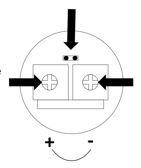
Adjustment for time delay (0.5 to 20 seconds) For Toggle. Turn clockwise to increase time delay
6. WIRING THE CM-221
1. Connection to a Door Operator
Connect the two trigger wires from the door operator to the blue and green wires on the CM-221. Then, connect the black wire of the CM-221 to the ground (-) of VDC power supply. Next, connect the red wire of the CM-221 to the positive (+) of the VDC power supply. Adjust to your needed range and output duration, using the potentiometers located on the back of the CM-221.
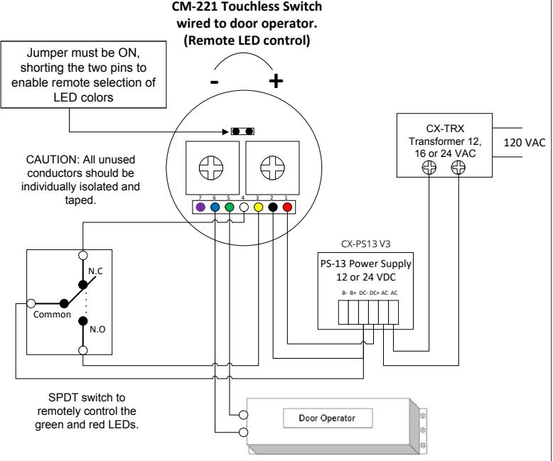
- Color Function Red 12 to 24 VDC Black 0 VDC (Ground) # 1 2
- Yellow Green LED controlled by external mode. White Red LED, controlled by external mode. 3
- Green Relay: Normally Open Blue Relay: Common Purple Relay: Normally Closed 4 5 6 7
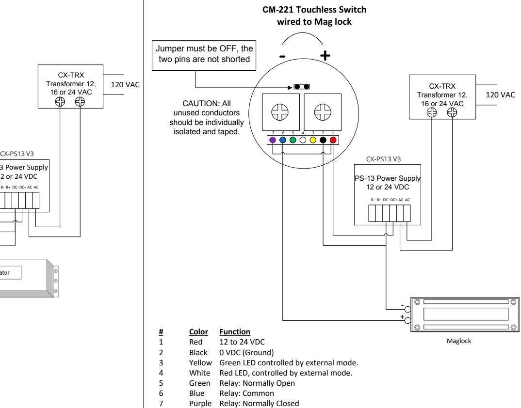
2. Connection to a Maglock
Connect the ground (-) of the maglock to the ground (-) of VDC power supply. Next, connect the positive (+) of the maglock to the blue wire (common) of the CM-221, then connect the purple wire (normally closed) to the to the positive (+) of the VDC power supply. Then, connect the black wire of the CM-221 to the ground (-) of VDC power supply. Next, connect the red wire of the CM-221 to the positive (+) of the VDC power supply. Adjust to your needed range and output duration using the potentiometers located on the back of the CM-221.
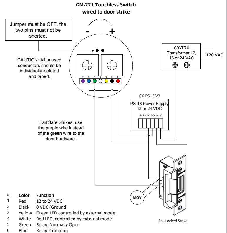
3. Connection to an External Strike
Connect the ground (-) of the strike to the ground (-) of VDC power supply. Next, connect the positive (+) of the strike to the blue wire (common) of the CM-221, then connect the green wire to the to the positive (+) of the VDC power supply. Then, connect the black wire of the CM-221 to the ground (-) of VDC power supply. Next, connect the red wire of the CM-221 to the positive (+) of the VDC power supply. Adjust to your needed range and output duration, using the potentiometers located on the back of the CM-221.
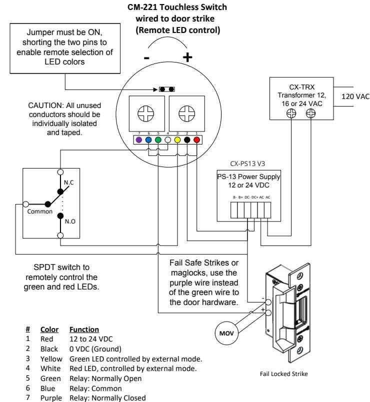
4. Connection to any Device using External LED Control
After using one of the typical wiring layouts as described above for any normally open or closed device you can now set up the remote LED triggering of the CM-221.
The red and green LED control wires will be wired through a SPDT (single pole double throw) contact. First, determine which color will be on and which color it will be switched to when remotely triggered. If you would like red to be on as the default, then connect the white wire from the CM-221 to the normally closed pole of the remote contact doing the switching. Then, connect the yellow wire to the normally open pole of the SPDT contact. Next, connect the common pole of the SPDT contact to the VDC ground of the VDC power supply being used. When the remote triggering system changes its contact, it will disconnect the white wire from the VDC ground and turn it off. At the same time, it will switch the yellow wire to ground turning on the green LED. If the opposite colors need to be switched then simply reverse the white and yellow wires on the contact.
Purple
Purple
Relay: Normally Closed
7. POWER
The CM-221 is a VDC device only and will accept a range of VDC power from 12VDC to 24VDC (+/- 10%). Do not connect AC voltage to the CM-221 at any time.
Note: A linear output VDC power supply is strongly recommended. If using power from other than Camden's CX-PS13 filtered regulated power supply, you must measure the provided power before applying power to the CM-221. Voltages of more than 10% over the specified acceptable range or using a power supply with large amounts of AC voltage on it (unfiltered unregulated power such as a transformer and a rectifier) may damage the CM-221 and void the warranty.
CM-221 TOUCHLESS EXIT SWITCH WITH REMOTE LED TRIGGERING
INSTALLATION INSTRUCTIONS
| FACEPLATE GRAPHIC OPTIONS | ||
|---|---|---|
| -xxx = | DESCRIPTION | |
| -42 |
Hand Icon, "Wave to Open" text and Wheelchair
Symbol |
|
| -42F |
Hand Icon, "Wave to Open" text and Wheelchair
Symbol, French |
|
| -A42 |
Hand Icon, "Wave to Open" text and Active Wheelchair
Symbol |
|
| -4A2F |
Hand Icon, "Wave to Open" text and Active Wheelchair
Symbol, French |
|
| -46 | Hand Icon, and "Wave to Exit". | |
| ORDERING INFORMATION FOR REPLACEMENT PARTS | |||||
|---|---|---|---|---|---|
| ITEM NUMBER | PART NUMBER | DESCRIPTION | |||
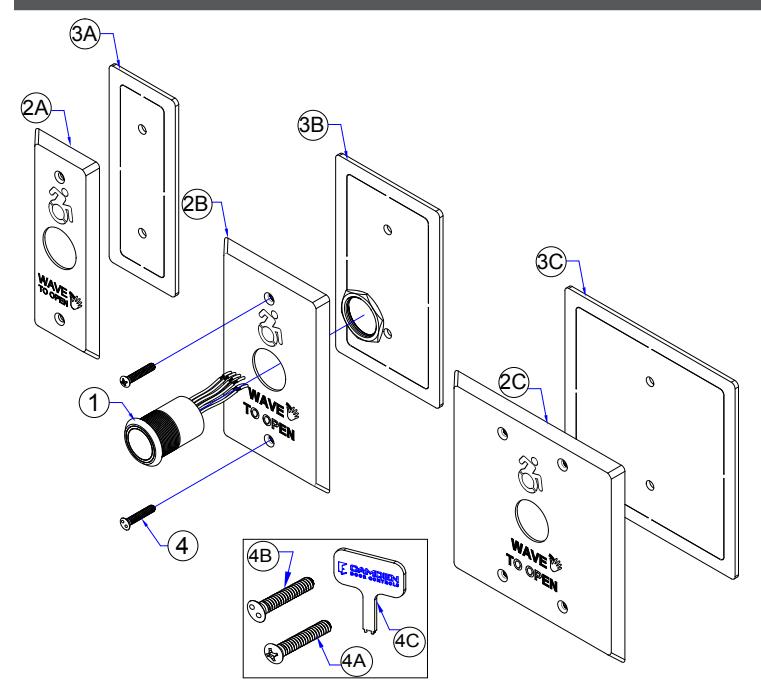
| 1. | 60-31A083 | TOUCHLESS SENSOR SWITCH WITH EXTERNAL LED CONTROL | |||
| 2. | A | 60-49B040-xxx | NARROW STAINLESS-STEEL FACEPLATE | ||
| B | 60-49H009L-xxx | SINGLE GANG STAINLESS-STEEL FACEPLATE | |||
| C | 60-49C058-xxx | DOUBLE GANG STAINLESS-STEEL FACEPLATE | |||
| 3. | A | 60-59H000 | GASKET FOR NARROW GANG TOUCHLESS SWITCH | ||
| B | 60-59H001 | GASKET FOR SINGLE GANG TOUCHLESS SWITCH | |||
| C | 60-59H003 | GASKET FOR DOUBLE GANG TOUCHLESS SWITCH | |||
| PARTS KIT | |||||
| ITEM NUMBER | PART NUMBER | DESCRIPTION | |||
| (A) 6-32 X 1/2" OVAL HD PHILLIPS SS SCREW | |||||
| 4. | 60-34B093 | (B) 6-32 X 1/2" SNAKE EYE SCREW | |||
| (C) KEY FOR TAMPER SNAKE EYE SCREW | |||||
| COMPATIBLE MOUNTING BOXES OPTION | |||||
| ITEM NUMBER | PART NUMBER | ||||
| FOR SINGLE GANG | DESCRIPTION | ||||
| CM-34AL |
SURFACE BOX, STANDARD DEPTH, THREADED CONDUIT ENTRY. HEAVY DUTY CAST ALUMINUM
2 3/4"W x 4 1/2"H x 1 3/4"D (70mm x 114mm x 45mm) |
||||
| CM-34BL |
ONE GANG BLACK ABS BOX, SURFACE MOUNT
2 7/8''W x 4 5/8''H x 1 3/4'' D (73mm x 117mm x 44mm) |
||||
| CM-66 |
FLUSH BOX & DRESS PLATE, STANDARD DEPTH BOX WITH 7'' x 7'' (178mm x 178mm) DRESS PLATE
HEAVY GAUGE STAINLESS STEEL |
||||
| FOR MULLION | |||||
| CM-23D | SURFACE BOX WITH EXTRA DEPTH, FLAME, AND IMPACT RESISTANT BLACK POLYMER (ABS) | ||||
| 1 3/4" W X 4 1/2"H X 1 3/4"D (46MM X 117MM X 43MM) | |||||
| FOR DOUBLE GANG | |||||
| CM-53 |
SURFACE BOX WITH STANDARD DEPTH DOUBLE WALL, FLAME/IMPACT RESISTANT BLACK
POLYMER (ABS) 4 1/2''W X 4 1/2''H X 2''D (115MM X 115MM X 51MM) |
||||
Visit: www.camdencontrols.com

Revision: 08/06/2020 Part No.: # 40-82B250