VLP-KIT-Insert-Instruction
Open the original PDF document
View PDF

VLPKIT Series
INSTALLATION INSTRUCTIONS
The VLPKIT 36" or 48" is a field installable solenoid latch pullback for the Von Duprin 33/35 & 98/99 series exit devices.
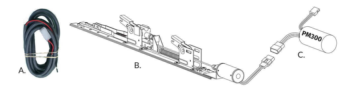
Includes
- A. 6' 2-Pin Power Lead
- B. Baserail Assembly
- C. PM300
- D. Dogging Cap
Tools Required
• Cordless Drill or Phillips Screwdriver
Doc # 20310_B

TECHNICAL INFORMATION
S PECIFICATIONS
- Wires: Input to PM300 non-polarized Black (+)(-)
- Operating Voltage Range: 22-30 VDC
- Coil Resistance Primary Coil: 2 ohms; Holding Coil: 125 ohm
- Output from PM300: Yellow=Pull Coil; Orange= Hold Coil; Green=Common
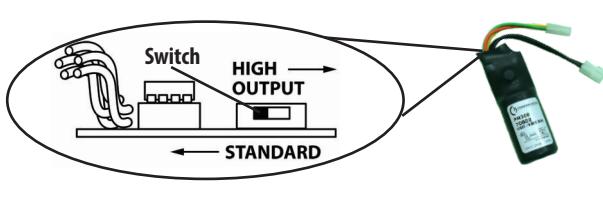
Standard Mode
• Fuse: Glass 3.5 - 5A, Resettable 1A trip •
Relay: 5A or greater
High Output Mode
Fuse: Resettable 2A trip
Relay: 10A or greater
Scan me

PM300 Compatibility Chart
TROUBLESHOOTING & DIAGNOSTICS
| SYMPTOM | Possible Cause | SOLUTION |
|---|---|---|
| Solenoid pulls back but releases immediately | Solenoid plunger not seating correctly |
|
| Solenoid pulls back and holds, but does not retract latch far enough | Plunger rod out of adjustment | Check plunger rod adjustment |
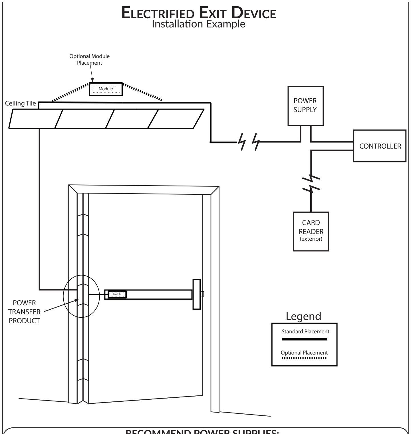
| Solenoid has excess delay time and/or drop out. | Wire run exceeding the maximum recommended distance | Locate power supply within the distances specified |

RECOMMEND POWER SUPPLIES:
All Command Access exit devices & field installable kits have been thoroughly cycle tested with Command Access power supplies at our factory.
• PS210
• PS220/220B
- PS440B
- PS480B
- PS1 • PS2/2B
- PS5-4
- PS5-6
For more information click here or go to our website

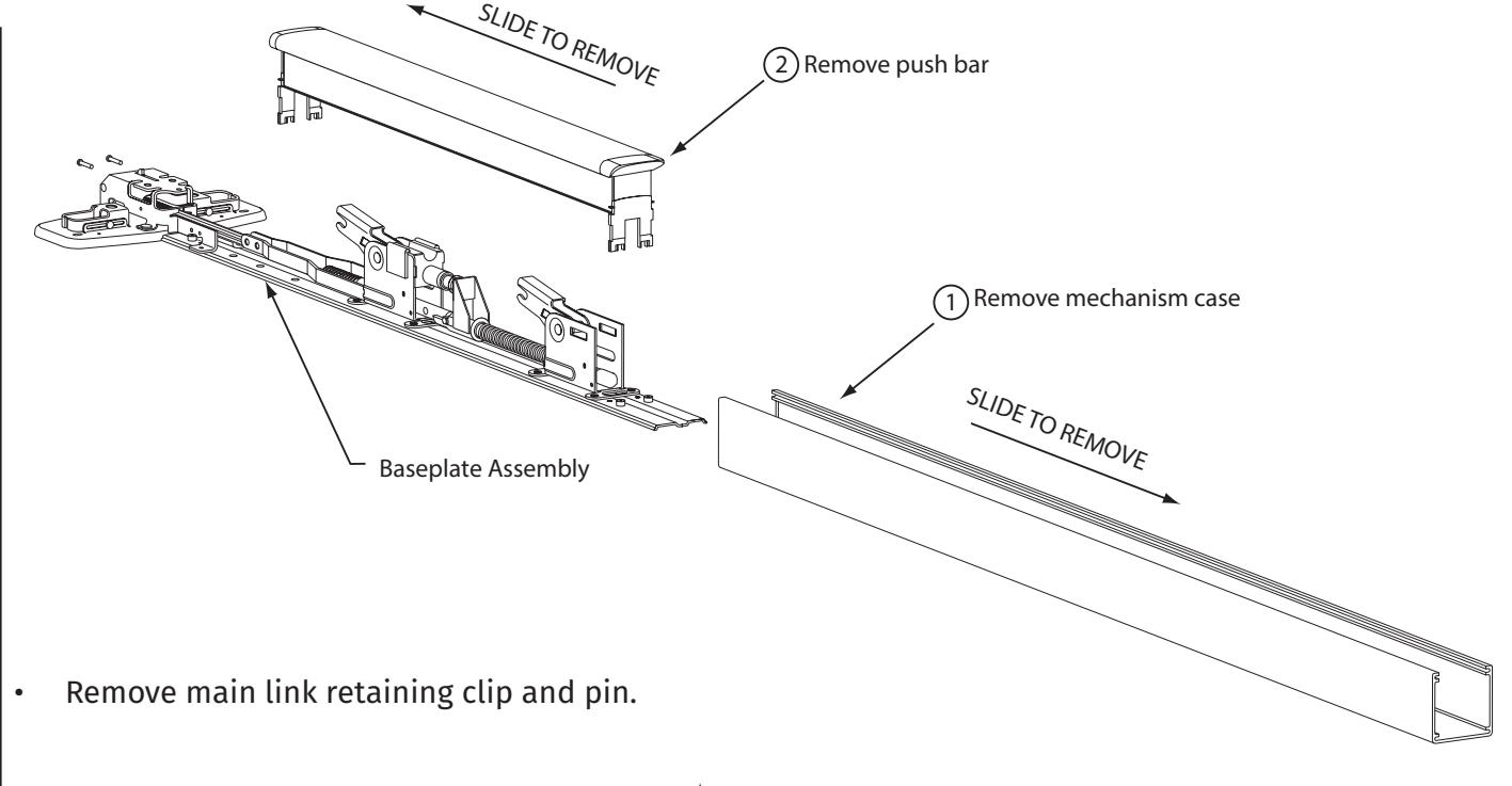
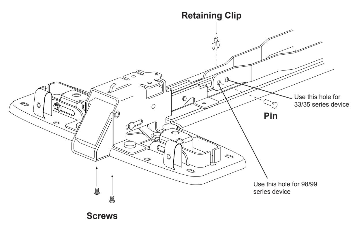
3 Remove screws connecting head (centercase) to baseplate. • Remove screws connecting head (centercase) to baseplate.
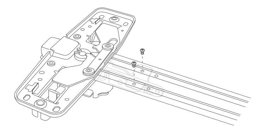

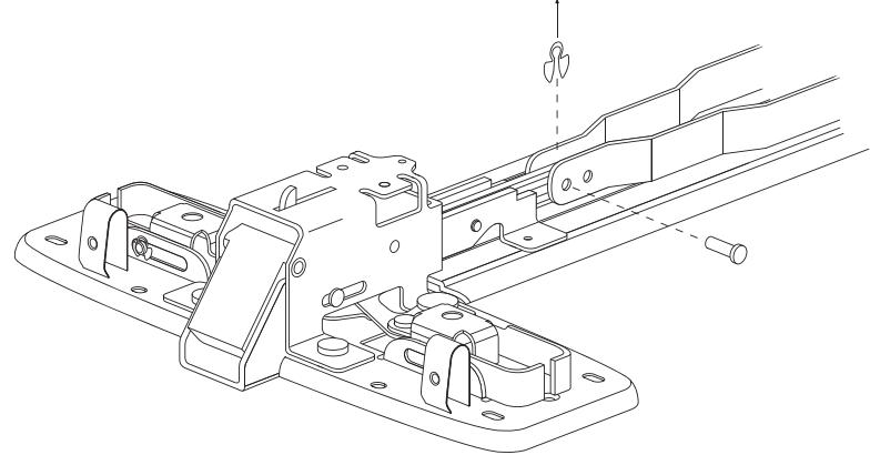
• Install head (centercase) to the EL baseplate using 2 screws. Place pin in correct hole for the device. Place retaining clip in the groove on the pin to secure the main line.
• Reassemble device. Place the PM300 in the area between the solenoid and the end cap.
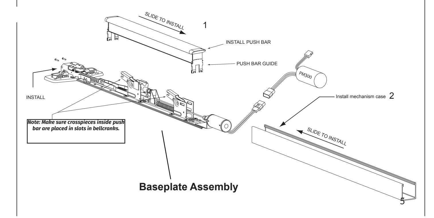

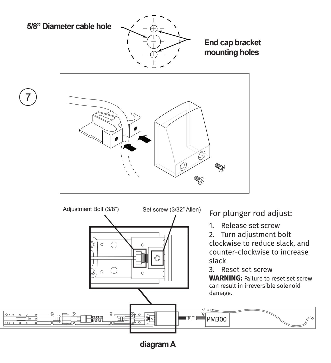
• Drill solenoid cable hole in door between end cap bracket mounting holes. Leave off dogging cover and end cap until wires are routed.