User Guide – Schlage Utility Software User Guide
Open the original PDF document
View PDF


Important Information
Customer Service
U.S.A.: 877-671-7011 www.schlage.com/support
Copyright
©2020 Allegion
Revision
This document has been updated for SUS Rev 6.8.2.
Check www.schlage.com/support for latest SUS revisions.
Important Information Warranty
Warranty
LIMITED WARRANTY: COMMERCIAL APPLICATIONS
12 Month Limited Warranty
Schlage Lock Company (the "Company") extends a 12 month limited warranty from the original date of purchase to the Original User of the products manufactured by the Company (the "Product") against defects in material and workmanship. Certain Products contain restrictions to this limited warranty, additional warranties or different warranty periods. Please see below for specific Product warranty information.
The provisions of this warranty do not apply to Products: (i) used for purposes for which they are not designed or intended; (ii) which have been subjected to alteration, abuse, misuse, negligence or accident; (iii) which have been improperly stored, installed, maintained or operated; (iv) which have been used in violation of written instructions provided by Schlage; (v) which have been subjected to improper temperature, humidity or other environmental conditions (i.e., corrosion); or (vi) which, based on Schlage's examination, do not disclose to Schlage's satisfaction non-conformance to the warranty. Additionally, Schlage will not warrant ANSI A156.2 Grade 2 lever Product installed in educational facilities and student housing.
Small Format Interchangeable Core (SFIC) Warranty: This limited warranty also applies to Schlage locks and housings when used with another manufacturer's cores, or to Schlage cores (i.e. SFIC) when used in another manufacturer's locks and housings. The use of unauthorized cylinder cams or other components with the Products shall void this warranty.
Everest® Primus® Limited Lifetime Key Breakage Warranty: A limited lifetime warranty is provided to the Original User against key breakage, subject to the restrictions of this limited warranty.
AD-Series 1-Year Warranty for electronic locks, reader modules, PIM400, and PIB300: A limited warranty is provided to the Original User for one (1) year from the date of installation, not to exceed 24 months from date of shipment from the factory, subject to the restrictions of this limited warranty.
CO-Series 1-Year Warranty for electronic locks, reader modules: A limited warranty is provided to the Original User for one (1) year from the date of installation, not to exceed 24 months from date of shipment from the factory, subject to the restrictions of this limited warranty.
ADDITIONAL TERMS & CONDITIONS APPLYING TO COMMERCIAL APPLICATIONS OF COMMERCIAL PRODUCTS
What the Company Will Do: Upon return of the defective Product to the Company, the Company's sole obligation, at its option, is to either repair or replace the Product, or refund the original purchase price in exchange for the Product.
Original User: This warranty only applies to the Original User of Products. This warranty is not transferable.
What is Not Covered: The following costs, expenses and damages are not covered by the provisions of this limited warranty: (i) labor costs including, but not limited to, such costs as the removal and reinstallation of Products; (ii) shipping and freight expenses required to return Products to Schlage; and (iii) any other incidental, consequential, indirect, special and/or punitive damages, whether based on contract, warranty, tort (including, but not limited to, strict liability or negligence), patent infringement, or otherwise, even if advised of the possibility of such damages. Some local laws do not allow the exclusion or limitation of incidental or consequential damages, so the above exclusion or limitation may not apply to you.
How Local Law Applies: This warranty gives you specific legal rights, and you may also have other rights as otherwise permitted by law. If this Product is considered a consumer product, please be advised that some local laws do not allow limitations on incidental or consequential damages or how long an implied warranty lasts, so that the above limitations may not fully apply. Refer to your local laws for your specific rights under this warranty.
Warranty Claims: If you have a claim under this warranty, please contact Schlage Customer Service (877-671-7011) for repair, replacement or refund of the original purchase price in exchange for the return of the Product to Schlage.
Miscellaneous: The Company does not authorize any person to create for it any obligation or liability in connection with the Product. The Company's maximum liability hereunder is limited to the original purchase price of the Product. No action arising out of any claimed breach of this warranty by the Company may be brought by the Original User more than one (1) year after the cause of action has arisen.
Contents
ii Important Information
- ii Customer Service
- ii Copyright
- ii Revision
- iii Warranty
Overview
Getting Started
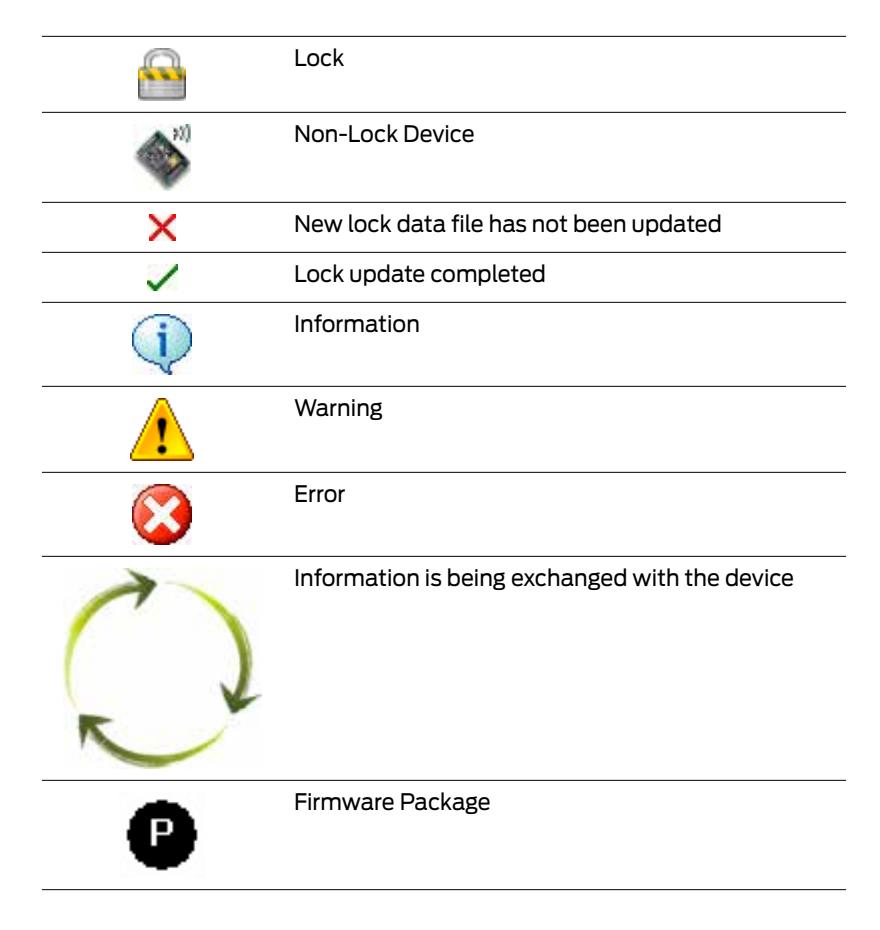
Icon Definitions
Logging In
Schlage Utility Software Options
- Connection Type
- Door List
- Update Mode
- SUS Password
- Coupling Password
- Language
- Device Template Feature
- Diagnostic Data Log Feature
Connecting the HHD
Connecting the Handheld Device
AD-Series Locks and Controllers
- Couple HHD to Lock
- Couple HHD to PIM400 or PIB300
- Couple HHD to WRI400/CT5000
- Program a Lock or Controller
- Collect Audits and Update Lock
- View Properties
- Edit Properties
- Edit Reader Properties
- Put PIM400 into Link Mode
- Put PIM400 into Diagnostics Mode
- Update Firmware
- Diagnostic Data Log Feature
- AD-Series Readers
- Lock Properties
- Controller Properties
CO-Series Locks
- Couple HHD to Lock
- Program a Lock
- Collect Audits
- View Properties
- Edit Properties
- View Reader Properties
- Edit Reader Properties
- Update Firmware
- Lock Properties
Legacy Locks and Controllers
- Program a Lock or Controller
- Collect Audits and Update a Lock
- View Properties
- Edit Properties
- Update Firmware
- Link a Door to a Legacy PIM
- Diagnostics
Troubleshooting
Glossary
Appendix A: SUS Update Guide
Appendix B: Device Firmware Update
- AD-Series On-Line Devices: Over Network Reprogramming (ONR).
- AD-Series and CO-Series Device Firmware Update
- Legacy Device Firmware Update
Appendix C: Change Lock Class
Appendix D: Device Template
Appendix E: Diagnostic Data Log
Index
Overview
The Schlage Utility Software is an application that runs on the Schlage Handheld Device (HHD). It is used to configure, edit and program all supported devices.
Supported Devices
| Locks and Controllers |
HHD Model
Compatiblity |
||
|---|---|---|---|
| BM-150 | BM-170 | ||
| AD-200 | • | • | |
| AD-201 | • | • | |
| AD-250 | • | • | |
|
AD-Series
Locks |
AD-300 | • | • |
| AD-301 | • | • | |
| AD-302 | • | • | |
| AD-400 | • | • | |
| AD-401 | • | • | |
| AD-402 | • | • | |
|
CO-Series
Locks |
CO-200 | • | • |
| CO-220 | • | • | |
| CO-250 | • | • | |
| KC2-5100 | • | • | |
| KC2-5500 | • | • | |
| KC2-9000 | • | • | |
| CM5100 | • | • | |
| CM5500 | • | • | |
| CM5200 | • | • | |
| CM5600 | • | • | |
| CM5700 | • | • | |
| Legacy Locks | CM993 | • | • |
| CL5100 | • | • | |
| CL5500 | • | • | |
| CL5200 | • | • | |
| CL5600 | • | • | |
| CL993 | • | • | |
| BE367 | • | • | |
| Locks and Controllers |
HHD Model
Compatiblity |
|||||
|---|---|---|---|---|---|---|
| BM-150 | BM-170 | |||||
| PIM400 | • | • | ||||
| AD-Series and Legacy Controllers | WRI400 | • | • | |||
| WPR400 | • | • | ||||
| PIB300 | • | • | ||||
| CT5000 Controller | • | • | ||||
| CT500 Controller | • | • | ||||
| CT1000 Controller | • | • | ||||
| WRI1 | • | • | ||||
| Legacy | WPR1 | • | • | |||
| PIM | WPR21 | • | • | |||
| WSM1 | • | • | ||||
|
CL Campus Lock
Controller |
• | • | ||||
1. These devices cannot be configured directly. They are configured through the legacy PIM.
SUS Functions by Device
| AD-Series Devices | AD-2002 | AD-250 | AD-3002 | AD-4001 2 | CT5000 | PIB300 |
M400
PI |
WPR4001 | WRI4001 |
|---|---|---|---|---|---|---|---|---|---|
| Collect Audits | • | • | • | ||||||
| Edit Lock Properties | • | • | • | • | • | ||||
| Edit PIB300 properties | • | ||||||||
| Edit PIM400 properties | • | ||||||||
| Edit Door Properties | • | • | • | • | |||||
| Update Firmware | • | • | • | • | • | • | • | • | • |
| Couple HHD to Device | • | • | • | • | • | • | • | • | • |
| Set Date/Time | • | • | • | • | • | • | |||
| Diagnostics | • | ||||||||
| Change Lock Class | • | • | • | • | • | • | • |
1. AD-Series wireless device properties may also be viewed or edited through the PIM400.
2. These devices work with the FIPS201 standard. AD-200 will become AD-201, AD-300 will become AD-301, and AD-400 will become AD-401 when a FMK reader is attached. If the FMK reader is attached to the WPR400, it will become WPR401.
| CO-Series Devices | |||
|---|---|---|---|
| CO-200 | CO-220 | CO-250 | |
| Collect Audits | • | • | • |
| Edit Lock Properties | • | • | • |
| Update Firmware | • | • | • |
| Couple HHD to Device | • | • | • |
| Set Date/Time | • | • | • |
| Legacy Devices | KC2 |
M
C |
CL | BE367 | CT500/1000 | CL Controller |
M
Legacy PI |
WA1 | WPR21 |
M1
WS |
WRI1 |
|---|---|---|---|---|---|---|---|---|---|---|---|
| Collect Audits | • | • | • | • | • | • | |||||
| Edit Lock Properties | • | • | • | • | • | • | |||||
| Update Firmware Update | • | • | • | • | • | • | • | ||||
| Edit Legacy PIM properties | • | ||||||||||
| Edit WAPM Properties | • | • | • | • | • | ||||||
| Diagnostics | • |
1. Legacy wireless access point devices cannot be configured directly. They are configured through the legacy PIM.
Getting Started
The Schlage Utility Software (SUS) is a software application that runs on a Windows CE based handheld device. It is used to transfer data files between the access control software and locks and controllers.
Quick Start
To begin using the SUS, review the following topics:
- 1 Download and Install Synchronization Software (page 9)
- 2 Connect the HHD to your PC (page 13)
- 3 Configure the Synchronization Software (page 10)
- 4 Update SUS (page 13)
- 5 Start SUS (page 15)
- 6 Connectng the Handheld Device to a Lock or Non-Lock Device (page 20)
Handheld Devices
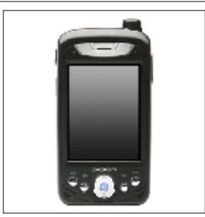

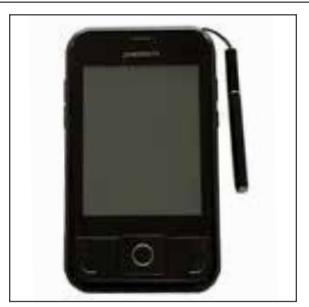
BM-150 HHD BM-170 HHD
| System Components | |||
|---|---|---|---|
| ID | BM-150 | BM-170 | Description |
| HHD KIT | · | · | Handheld Device pre-loaded with SUS, USB Cable |
| HH-USB | · | · | Cable used to connect HHD to AD- and CO-Series products. |
| HH-Serial | · | n/a |
Cable used to connect HHD to CIP for programming legacy
CM/CL/KC products. |
| · | · |
Cable used to connect HHD to Null converter for programming
WA Series Legacy PIM. |
|
| PIMWA-CV | · | · |
Null converter used to connect HHD to WA Series Legacy PIM,
using the HH-Serial Cable. |
| CIP (P512-112) | · | n/a |
CIP Module used with HH-Serial Cable for programming legacy
CM/CL/KC products. |
|
HH-2PIN Serial
Black |
· | · |
Cable used to connect HHD for programming legacy CM/CL/KC
products. Must have SUS 6.3.3 in HHD to support the HH-2PIN Serial cable. |
|
HH-2PIN Serial
Gray |
· | · |
Cable used to connect HHD for programming legacy BE367/
FE210 products. Must have SUS 6.5.3 in HHD to support the HH-2PIN Serial cable. |
Synchronization Software
About Synchronization Software
Synchronization software is software that your computer uses to interface and synchronize with the handheld device. This software is used to install and update software applications on your handheld device. When installed and configured properly, files will be automatically transferred between your computer and the handheld device when the handheld device is connected to the computer.
Î This software may already be installed on your computer.
Download and Install Synchronization Software
-
1
Download the software that matches your operating system.
- Windows 10, Windows 8, Windows 7 and Windows Vista:
-
Windows XP and Windows 2000:
- 32 and 64 Bit: http://www.microsoft.com/en-us/download/details.aspx?id=15
- 2 Launch the installer and follow the on-screen instructions.
Configure Synchronization Software
Microsoft ActiveSync is for use with Windows XP and Windows 2000 operating systems.
Microsoft ActiveSync
- 1 Connect the handheld device to the computer's USB port. The Synchronization Setup Wizard will appear.
- 2 Click the Next button.
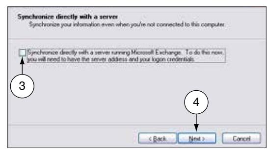
- 3 Uncheck the check box next to Synchronize directly with a server .
- 4 Click the Next button.
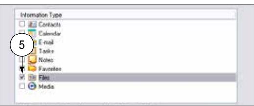
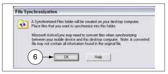
- 5 Uncheck all the check boxes except for the check box next to Files .
A new folder will be created on the computer to store the synchronized files.
6 The File Synchronization window will appear. Click OK .

Microsoft Windows Mobile Device Center is for use with Windows 10, Windows 8, Windows 7 and Windows Vista operating systems.
Microsoft Windows Mobile Device Center
- 1 Open the Windows Mobile Device Center from the computer.
- 2 Connect the handheld device to your computer's USB port.
- 3 Click Setup your device .
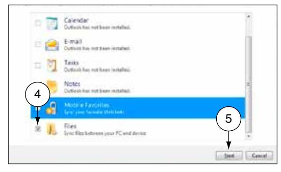
- 4 Click to uncheck all check boxes except for the Files check box.
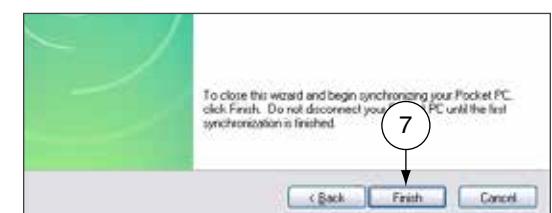
- 5 Click the Next button.

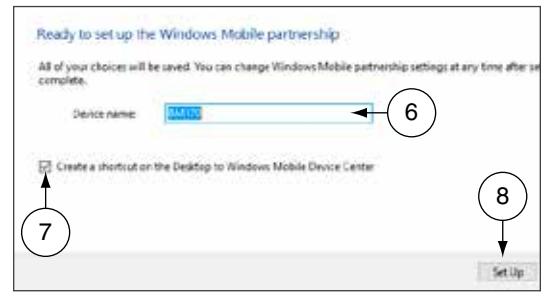
- 7 Check the Create a shortcut on the Desktop... checkbox.
- 8 Click the Set Up button.

Synchronization software must be installed so that the handheld device can communicate with the computer. See Synchronization Software on page 9 for more information.
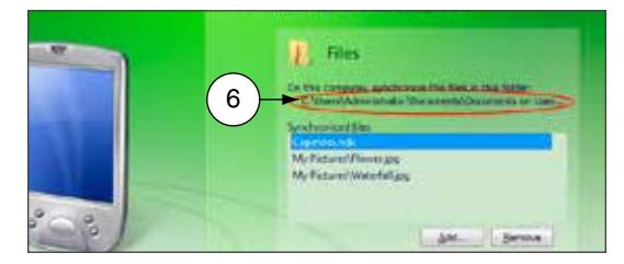
Locate the Synchronization Folder
The synchronization software looks in this folder for files that should be synchronized with the handheld device. When you configure your access control software, you need to know the location of this file on your computer.
Microsoft ActiveSync
-
1
Connect the HHD to the PC and allow ActiveSync to start.
- Î If Microsoft ActiveSync does not open automaticaly, click on Start > Programs > Microsoft ActiveSync .
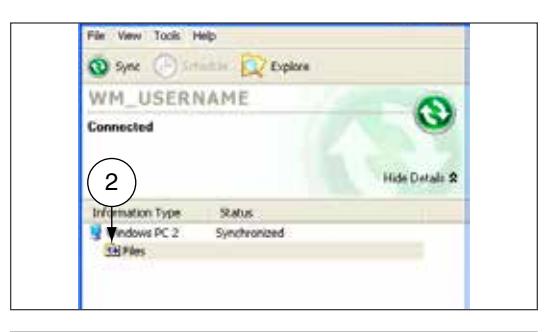
- 2 In the bottom half of the ActiveSync screen, double click on the Files folder.

- Î This path may extend beyond the edges of the box. Make sure to view the entire path.
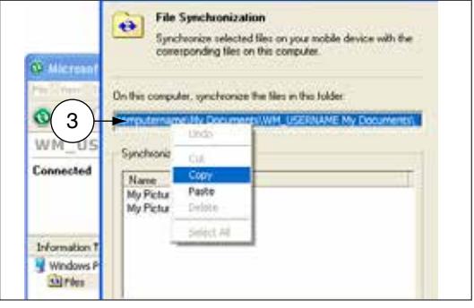
- 4 To ensure the path is entered into the access control software correctly, highlight the path and then copy (Ctrl + C) and paste (Ctrl + V) it into the access control software.
Microsoft Windows Mobile Device Center
- 1 If Microsoft Windows Mobile Device is not already open, click on Start > Programs > Microsoft Windows Mobile Device Center .
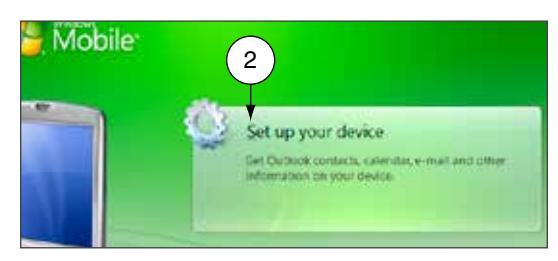
- 2 Click Set up your device .
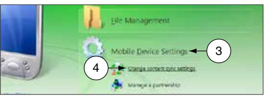
- 3 Click Mobile Device Settings .
- 4 Click Change content sync settings .
- 5 Click Sync Settings .
- 6 The sync folder path is located below the Files icon.
- 7 To ensure the path is entered into the access control software correctly, highlight the path and then copy (Ctrl + C) and paste (Ctrl + V) it into the access control software.

Connect the Handheld Device to the PC
If the HHD does not automatically synchronize with the PC, be sure that the SUS application is not running. The SUS will prevent USB communication with your PC.
- 1 Locate the HH-USB cable that came in the box with the handheld device. Insert the USB end into the computer's USB port.
- 2 Power on the handheld device.
- 3 Insert the other end of the cable into the bottom of the handheld device.
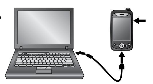
Connecting the Handheld Device to the PC
Install/Update Schlage Utility Software
Although SUS is already installed on your handheld device, you should make sure you have the latest revision of the software.
- 1 Download the installer (Schlage Utility Setup Ver x.x.xx.exe, version will vary) from www.schlage.com/ support .
- 2 Make sure you have already installed and configured the synchronization software.
- 3 Make sure the handheld device is connected to the computer's USB port and is turned on.
- 4 Launch the installer.
- 5 Follow the on-screen instructions. The synchronization software will automatically transfer the software to the handheld device.
-
6
When updating Schlage Utility Software all passwords are reset to their defaults.
- Î See Appendix A: SUS Update Guide on page 76 for detailed instructions about upgrading the Schlage Utility Software on the Handheld Device.
Synchronization software must be installed and configured on your computer in order for these steps to work properly. See Download and Install Synchronization Software on page 9 for more information.
Icon Definitions
Logging In
You can log in to the Schlage Utility Software (SUS) as either a Manager or an Operator. The Manager role has access to all commands. The Operator role has access only to limited commands.
| Manager | Operator | |
|---|---|---|
| Lock Properties | • | • |
| Program Lock | • | • |
| Firmware Update | • | |
| Change Lock Class | • | |
| Couple HHD to Device | • | |
| Set Date/Time | • | |
| Diagnostic Data Log | • | • |
| Door Properties | • | • |
| PIM properties | • | • |
| Diagnostics | • | |
| SUS Password | • | • |
| Coupling Password | • | |
| Language | • | • |
| Auto/Manual Update | • | • |
| List All/Pending Doors | • | • |
| USB/Serial Connection | • | • |
Start the Schlage Utility Software
1 On your handheld device, tap the Start menu. 2 Tap Programs .
3 Tap the Schlage Utility Software icon.
4 Log on as either a Manager or an Operator.
5 If you are starting the SUS for the first time, change the Manager and Operator passwords, and the Coupling Password, to maintain security.
Î See SUS Password on page 18 for more information.
Î See Coupling Password on page 18 for more information.
Logging In Log in as a Manager
Log in as a Manager
The default password for both the Manager and Operator is 123456.
If the password is lost, you must reinstall SUS. Customer service cannot retrieve a lost password.
-
1
If you have not already started the Schlage Utility Software, do so now.
- Î See Start the Schlage Utility Software on page 15 for more information.
- 2 Choose Manager from the drop-down list.
- 3 Enter the manager password in the password box.
-
4
Select the
Login
button.
- Î See SUS Password on page 18 for more information.
Log in as an Operator
-
1
If you have not already started the Schlage Utility Software, do so now.
- Î See Start the Schlage Utility Software on page 15 for more information.
- 2 Choose Operator from the drop-down list.
- 3 Enter the operator password in the password box.
-
4
Select the
Login
button.
- Î See SUS Password on page 18 for more information.
Schlage Utility Software Options
Connection Type
AD/CO-Series devices communicate with the SUS via USB connection. Legacy devices communicate with the SUS via Serial connection. Select this option to match the device type to which you are connecting. If you have both types of devices in your facility, you will need to change this setting during a tour.
- 1 Select SUS Options .
- 2 Select Connection Type .
- 3 Select USB Connection or Serial Connection .
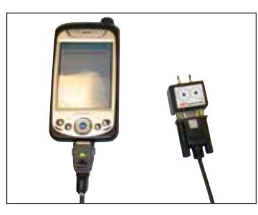
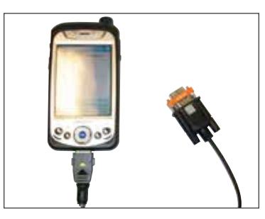
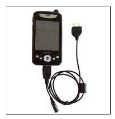
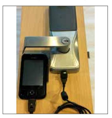
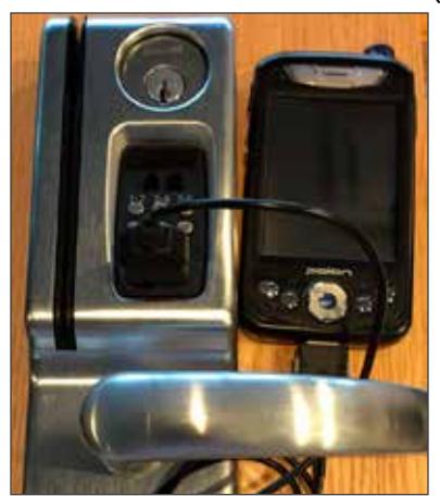
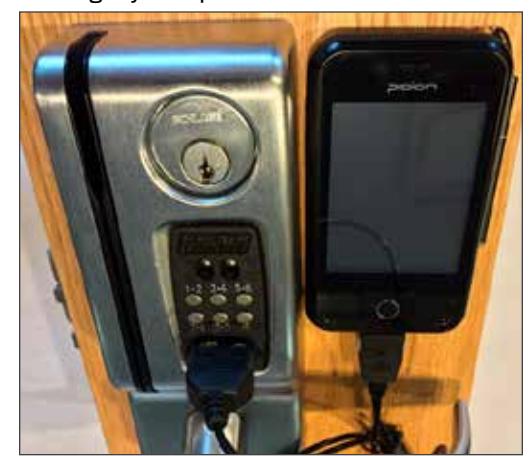
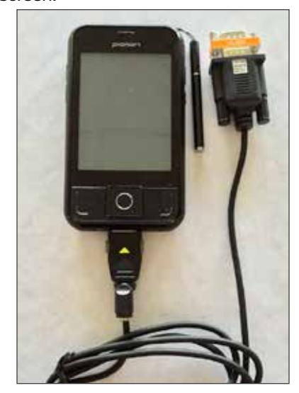
Connection Examples
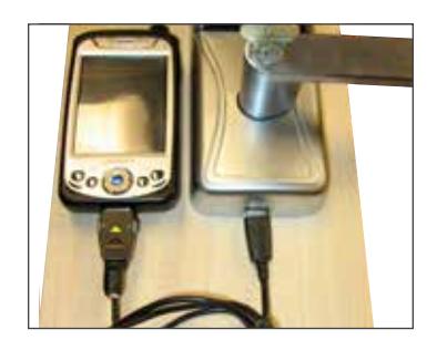
USB Connection with BM-150 Serial Communication with CIP (BM-150 only)
Serial Communication with Null Modem (PIMWA-CV) (BM-150)
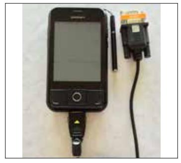
Serial Communication with 2PIN Serial Cable (BM-150)
USB Connection with BM-170 Serial Communication with
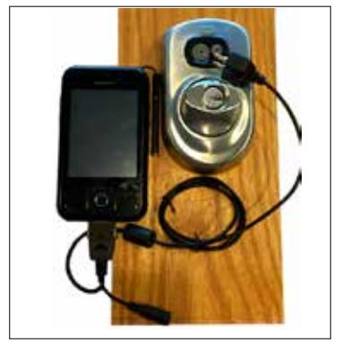
2PIN Serial Cable (BM-170)
Serial Communication with Null Modem (PIMWA-CV) (BM-170)
Door List
If you want to display only the doors that need to be toured, set this setting to List Pending Doors . Select List All Doors to display all doors that have been updated and pending.
- 1 Select SUS Options .
- 2 Select Door List .
- 3 Select List All Doors or List Pending Doors .
Update Mode
When Auto Update is selected, the SUS will automatically set the date and time in the lock to which it is connected, retrieve the audit and program the lock. When Manual Update is selected, the functions must be independently performed by the user.
-
Î Manual Update is recommended when managing Legacy Locks.
- 1 Select SUS Options .
- 2 Select Update Mode .
- 3 Select Auto Update or Manual Update .
SUS Password
You must be logged in to a role to change the password for that role.
- 1 Select SUS Options .
- 2 Select SUS Password .
- 3 Enter the old password into the Old Password box.
-
4
Enter the new password into the
New Password
box.
- Î The new password must be between four (4) and eight (8) characters long and can include capital and lowercase characters, numbers, and symbols.
- 5 Enter the new password again into the Confirm New Password box.
- 6 Select the Submit button.
This function is available only when logged into the handheld device as a manager.
The default Coupling Password is 123456.
Coupling Password
- 1 Select SUS Options .
- 2 Select Coupling Password .
- 3 Enter the old password into the Old Password box.
-
4
Enter the new password into the
New Password
box.
- Î The new password must be between four (4) and eight (8) characters long and can include capital and lowercase characters, numbers, and symbols.
- 5 Enter the new password again.
- 6 Select Submit .
Language
- 1 Select SUS Options .
- 2 Select Language .
- 3 Select the button for the language to which you want to change.
- 4 Select the OK button.
Device Template Feature
The Device Template feature facilitates creation, modification and duplication of Device Properties settings across multiple devices. In addition, the Device Template will also report additional device status parameters for a complete summary of the device's health.
Locating the Device Template Feature:
- 1 Select Device Options
- 2 Select Lock Properties for the connected device
- 3 Select the Edit or Reader tab
- 4 The Device Template is at the bottom of the screen
- Î For details on the Device Template feature, see Appendix D: Device Template on page 90 .
Diagnostic Data Log Feature
This new feature provides a simple method for AD-Series customers to quickly gather and save important lock-status information in a file.
Î For details see Appendix E: Diagnostic Data Log on page 92 .
Connecting the HHD
Connecting the Handheld Device
The Schlage button will flash green while the lock is waiting to communicate with the HHD. The Schlage button will begin to flash red when communication between the lock the HHD is established.
When communication is established, the device name will be displayed on the SUS main screen.
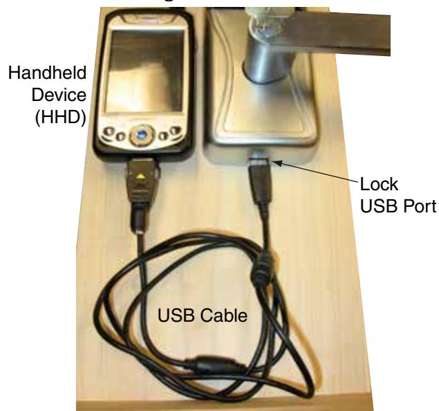
AD-Series and CO-Series Locks
- 1 Start the Schlage Utility Software.
- 2 Make sure the HHD is in USB Connection Mode. See Connection Type on page 17 for more information.
- 3 Connect the USB cable to the HHD.
- 4 Plug the HHD USB cable into the lock's USB port located in the bottom of the exterior housing.
- 5 Press the Schlage button twice.
BM-150 BM-170
When communication is established, the device name will be displayed on the SUS main screen.
AD-Series Controllers
- 1 Start the Schlage Utility Software.
- 2 Make sure the HHD is in USB Connection Mode. See Connection Type on page 17 for more information.
- 3 Connect the USB cable to the HHD.
- 4 Plug the HHD USB cable into the controllers's USB port. Communication will begin automatically
When communication is established, the device name will be displayed on the SUS main screen.
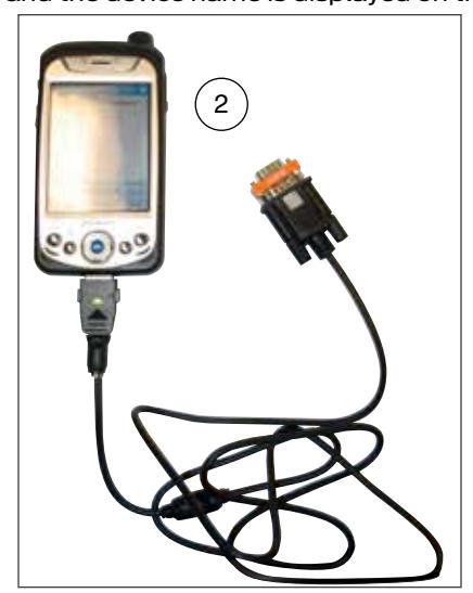
Legacy CM and CL Locks (BM-150 with Serial Cable and CIP ONLY)
- 1 Start the Schlage Utility Software.
- 2 Make sure the HHD is in Serial Connection Mode. See Connection Type on page 17 for more information.
- 3 Connect the serial cable (HH-Serial) to the HHD and the CIP.
- 4 Connect the CIP to the legacy lock port.
Legacy CM and CL Locks (BM-150 and BM-170 with 2PIN serial cable)
- 1 Start the Schlage Utility Software
- 2 Make sure the HHD is in Serial Connection Mode. See Connection Type on page 17 for more information.
- 3 Connect the 2PIN serial cable to the (HHD) and the Legacy lock port.

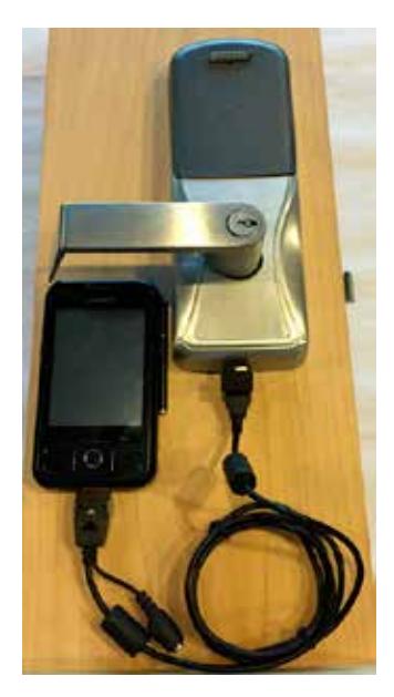
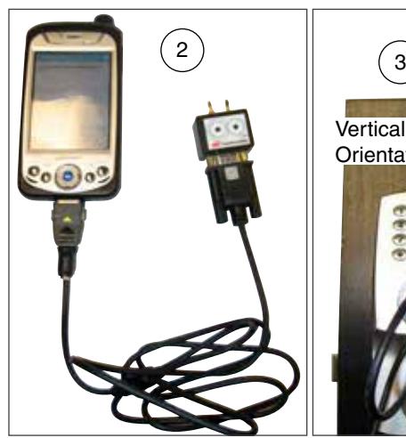
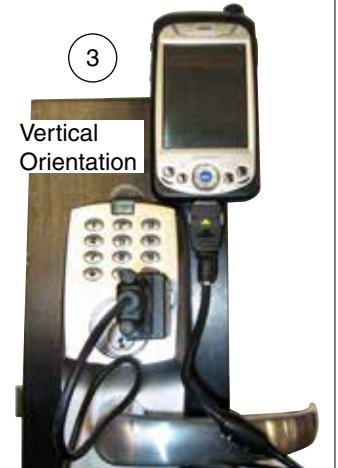
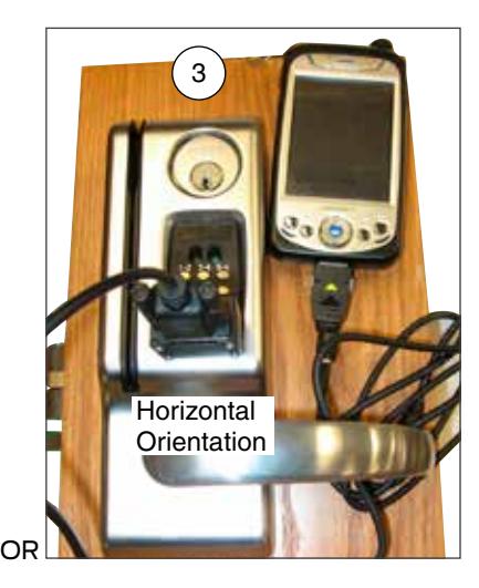
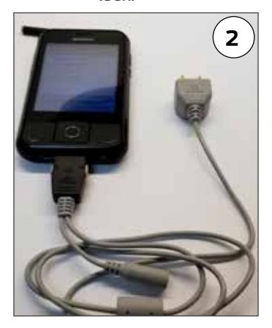
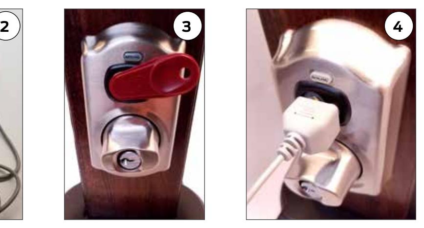
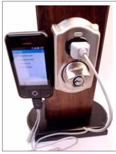
Legacy BE367 and FE210 Locks (BM-150 with Serial Cable and CIP ONLY)
- 1 Start the Schlage Utility Software.
- 2 Make sure the HHD is in Serial Connection Mode. See Connection Type on page 17 for more information.
- 3 The deadbolt must be retracted if this is the first time programming the lock.
- 4 Connect the serial cable (HH-Serial) to the HHD and the CIP.
- 5 Present the red programming iButton to the lock.
-
6
Connect the CIP to the lock port.
- Î Rotate the thumbturn to the horizontal position, as shown, before connecting the CIP to the lock.
Legacy BE367 and FE210 (BM-150 and BM-170 with 2PIN serial cable)
- 1 Start the Schlage Utility Software
- 2 Make sure the HHD is in Serial Connection Mode. See Connection Type on page 17 for more information.
- 3 The deadbolt must be retracted if this is the first time programming the lock.
- 4 Present the Red programming iButton to the lock.
- 5 Connect the 2PIN serial cable to the (HHD) and the lock port.
BM-150 BM-170
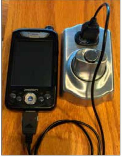
Legacy PIM
- 1 Start the Schlage Utility Software.
- 2 Make sure the HHD is in Serial Connection Mode. See Connection Type on page 17 for more information.
- 3 Connect the serial cable (HH-Serial) to the HHD and the null modem adapter (PIMWA-CV).
- 4 Connect the null modem adapter to the legacy PIM serial port.
- 5 Simultaneously press the RESET and the LINK A buttons on the Legacy PIM, then release the RESET button while holding the LINK A button.
- 6 Continue holding the LINK A button (at least 15 seconds) until communication is established and the device name is displayed on the SUS main screen.
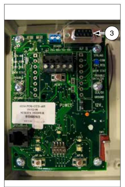
Legacy PIM
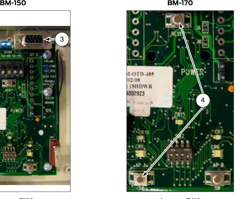
Legacy PIM
AD-Series Locks and Controllers
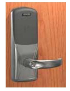
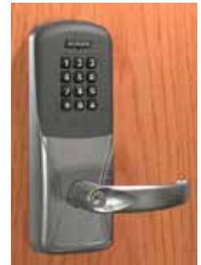
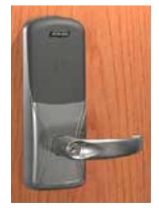
Supported Locks
All chassis for the following models are supported.
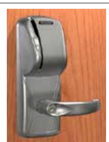
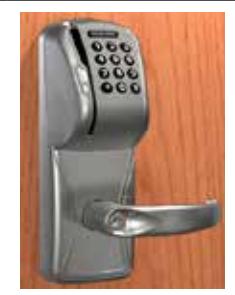
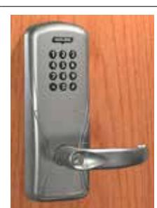
AD-Series Offline
AD-200 AD-250
AD-201
AD-Series Networked
AD-300 AD-301 AD-302 AD-400 AD-401 AD-402
Supported Controllers
PIM400 (Panel Interface Module) WRI400 (Wireless Reader Interface) WPR400 (Wireless Portable Reader) PIB300 (Panel Interface Board) CT5000 Controller
This function works with AD-Series devices only.
Couple HHD to Lock
AD-Series locks can be coupled, or authenticated, with the HHD. This provides enhanced security by ensuring that the lock will only communicate with HHD(s) to which it has been coupled. Once the lock has been coupled, the Coupling Password is passed to the device from the HHD during programming.
-
Î HHDs with the same coupling password can program the same devices. Once the HHD and lock are coupled, the coupling password is disabled in the lock and any HHD with the correct coupling password will automatically couple with the lock.
-
1
Connect the HHD to the lock using the HH-USB cable.
- Î The HHD must be in USB mode. See Connection Type on page 17 for more information.
- 2 Press the Schlage button twice. The lock will be displayed on the screen.
- 3 On the HHD, select Device Options .
- 4 Remove the top inside lock cover.
- 5 Press and hold the Inside Push button. Then press and release the tamper switch three times.
-
1
Connect the HHD to the lock using the HH-USB cable.
- 6 Release the Inside Push button. On the lock, the Inside Push button LED will illuminate.
- 7 On the HHD, select Couple HHD to Device .
- 8 When Coupling is successful, a message will be displayed on the screen.
The HHD will use a default Coupling Password (123456) when coupling with a device. The Coupling Password should be changed to provide increased security for your locks. See Coupling Password on page 18 for more information.
If a device is not in Coupling mode, SUS will display a device specific message with instructions for placing the device into Coupling mode.
This function works with AD-Series devices only.
The HHD will use a default Coupling Password (123456) when coupling with a device. The Coupling Password should be changed to provide increased security for your locks. See Coupling Password on page 18 for more information.
If a device is not in Coupling mode, SUS will display a device specific message with instructions for placing the device into Coupling mode.
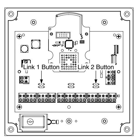
Couple HHD to PIM400 or PIB300
AD-Series devices can be coupled, or authenticated, with the HHD. This provides enhanced security by ensuring that the device will only communicate with HHD(s) to which it has been coupled. Once the device has been coupled, the coupling password is passed to the device from the HHD during programming.
-
Î HHDs with the same coupling password can program the same devices. Once the HHD and the device are coupled, the coupling password is disabled in the PIM400 or PIB300 and any HHD with the correct coupling password will automatically couple with the PIM400 (or PIB300).
- 1 Remove the PIM400 or PIB300 cover.
- 2 The HHD must be in USB mode. See Connection Type on page 17 for more information.
- 3 Connect the HHD to the PIM400 or PIB300 using the HH-USB cable. The PIM400 or PIB300 will be displayed on the HHD screen.
- 4 On the HHD, select Device Options .
- 5 On the PIM400 or PIB300, press and hold the LINK 1 button. Then press the LINK 2 button three times.
- 6 On the HHD, select Couple HHD to Device .
- 7 When Coupling is successful, a message will be displayed on the HHD screen.
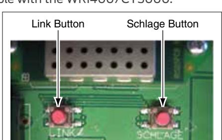
Couple HHD to WRI400/CT5000
The WRI400/CT5000 can be coupled, or authenticated, with the HHD. This provides enhanced security by ensuring that the device will only communicate with HHD(s) to which it has been coupled. Once the device has been coupled, the programming password is passed to the device from the HHD during programming.
-
Î HHDs with the same programming password can program the same devices. Once the HHD and the device are coupled, the coupling password is disabled in the WRI400/CT5000 and any HHD with the correct coupling password will automatically couple with the WRI400/CT5000.
- 1 Remove the device cover.
- 2 The HHD must be in USB mode. See Connection Type on page 17 for more information.
- 3 Connect the HHD to the device using the HH-USB cable. The name of the device will be displayed on the HHD screen.
- 4 On the HHD, select Device Options .
- 5 On the WRI400/CT5000, press and hold the Schlage button. Then press the LINK button three times within five (5) seconds. Then release both buttons.
- 6 On the HHD, select Couple HHD to Device .
- 7 When Coupling is successful, a message will be displayed on the HHD screen.
Program a Lock or Controller
Offline Locks
- 1 Connect the HHD to the lock or controller and establish communication between the HHD and the device.
- 2 Select Device Options .
- 3 Select Program Lock .
-
4
Select the door file that should be associated with the lock or controller.
- Î Door files are downloaded to the HHD when synchronized with the access control software.
- 5 Select OK .
Online Locks
Î NOTE: This function is not applicable to online locks.
Collect Audits and Update Lock
When Auto Update is enabled, as soon as the Schlage button is pressed twice and the communication with the Schlage Utility Software starts, the lock will automatically:
- update lock's date/time
- collect audits
- update access rights
When Manual Update is enabled, follow the steps below to collect audits and update the lock access rights.
Î See Update Mode on page 18 for more information.
Collect Audits when Date/Time and Lock Access Rights are Up-to-Date
-
1
Confirm HHD is connected to lock.
- Î See Connecting the Handheld Device on page 20 for more information.
- 2 Double-click the displayed name of the connected lock.
-
3
The audit collection will begin.
- Î If no previous audit exists, skip to step 7.
- 4 If a previous audit exists, a message will appear asking to overwrite previous audit. Click YES to override audits and skip to step 7.
- 5 Click NO if you do not want to override the audit.
- 6 Acknowledge the message advising to synchronize the lock with system software. Audit collection will be stopped.
- 7 A progress indicator will be displayed while the audit is being collected. A message will be displayed once the process is complete.
Collecting audits on the HHD does not delete the audits from a lock.
Collected audits will be transferred from HHD to your Access Control Software the next time they are synchronized.
Collect Audits when Date/Time and Lock Access Rights are Not Up-to-Date
-
Confirm HHD is connected to lock.
- Î See Connecting the Handheld Device on page 20 for more information.
- Double-click the displayed name of the connected lock.
- When asked to update date and time of the device, click YES . A progress indicator will be displayed while date and time is being updated.
- A message will appear to confirm the successful update.
- The audit collection will begin. A progress indicator will be displayed while the audit is being collected.
- The access rights update will begin. A progress indicator will be displayed while lock is being updated.
- A message will be displayed once the process is complete.
View Properties
- Connect the HHD to the lock or controller.
- Select Device Options .
- Select Properties for the connected device.
-
The
View
tab will be displayed.
- Î See Lock Properties on page 31 for more information.
Edit Properties
- Connect the HHD to the device.
- Select Device Options .
- Select Properties for the connected device.
- Select the Edit tab.
-
Edit the properties as desired.
- Î See Lock Properties on page 31 for more information.
- Select Save to update and save the changes.View Reader Properties
- Connect the HHD to the device.
- Select Device Options .
- Select Properties for the connected device.
-
Select the
Reader
tab.
- Î See Lock Properties on page 31 for more information.
Edit Reader Properties
- Connect the HHD to the device.
- Select Device Options .
- Select Properties for the connected device.
- Select the Reader tab.
- Edit the properties as desired.
-
Select
Save
to update and save the changes.
- Î See Lock Properties on page 31 for more information.
Put PIM400 into Link Mode
- 1 Connect the HHD to the PIM400.
- 2 Select Device Options .
- 3 Select PIM Properties for the connected device.
- 4 Select the Link tab.
-
5
Select the door number from the drop-down box.
- Î See the system administrator for the proper door number selection.
- 6 The PIM400 will stay in link mode for up to 30 minutes.
-
7
Put the lock (door) into link mode.
- Î See the user guide that came with the lock for more information.
- 8 The PIM400 will automatically exit link mode once linking is complete.
Put PIM400 into Diagnostics Mode
- 1 Connect the HHD to the PIM400 and select Device Options.
-
2
Select Diagnostics and then select the door number from the drop-down box.
- Card Data box: shows card data from credential when card presented to reader.
- Unlock on Read: if enabled allows the door to be unlocked upon the reading of a card: the OEM has the ability to disable this feature (grayed out).
Update Firmware
Î See AD-Series and CO-Series Device Firmware Update on page 78 for more information.
Diagnostic Data Log Feature
This new feature provides a simple method for AD-Series customers to quickly gather and save important lock-status information in a file. For details see Appendix E: Diagnostic Data Log.
AD-Series Readers
The Multi-Tech and Multi-Tech + Keypad readers will read both proximity and smart cards. The Proximity, Proximity + Keypad ONLY and Smart Card, Smart Card + Keypad ONLY readers have been discontinued and replaced by the MultiTech, Multi-Tech + Keypad readers that provide all the same functionality as the original Proximity and Smart card readers in a single credential reader.
Multi-Tech Multi-Tech + Keypad
The MiK and SiK2 readers are both a solution for applications using the HID iClass smart card credential.
iCLASS® is a proprietary smart card technology developed by HID that operates on ISO 15693. In order to support these requirements, iClass + Multi-Tech + Keypad reader were integrated to create the (MiK) and (SiK2). (SiK2) is not capable of reading Proximity credentials.
iClass + Multi-Tech iClass + Multi-Tech + Keypad
The FMK reader module is for applications which require approval by the U.S. Federal Government under HSPD-12 for FIPS 201 compliance. In order to meet these requirements, FIPS + Multi-Technology + Keypad reader were integrated to create the (FMK).
FIPS + Multi-Tech + Keypad
MagInsert MagInsert + Keypad
MagSwipe MagSwipe + Keypad
Keypad
| Reader Types | |
|---|---|
| Reader Description | Reader Type Shown in SUS |
| Mag Insert with Keypad | MagInsert + Keypad |
| Mag Insert without Keypad | MagInsert |
| Mag Swipe with Keypad | MagSwipe + Keypad |
| Mag Swipe without Keypad | MagSwipe |
| Keypad Only | Keypad |
| Prox with Keypad | Proximity + Keypad |
| Prox without Keypad | Proximity |
| Smart with Keypad | Smart Card + Keypad |
| Smart without Keypad | Smart Card |
| FMK Reader | FIPS + Multi-Tech + Keypad |
| MT | Multi-Tech |
| MTK | Multi-Tech + Keypad |
| Mi | iClass + Multi-Tech |
| MiK | iClass + Multi-Tech + Keypad |
| MT2 | Multi-Tech 2 |
| MTK2 | Multi-Tech 2 + Keypad |
| FMK2 | FIPS + Multi-Tech 2 + Keypad |
| KP2 | Keypad 2 |
| Si2 | iClass + Smart Only 2 |
| SiK2 | iClass + Smart Only 2 + Keypad |
Î Note: (Multi-Tech, Multi-Tech + Keypad) and (iClass + Multi-Tech, iClass + Multi-Tech + Keypad) and (FIPS + Multi-Tech +Keypad) and (Keypad) readers are being discontinued (1st half 2016) and replaced by the (Multi-Tech 2, Multi-Tech + Keypad 2) and (FIPS + Multi-Tech +Keypad 2) and (Keypad 2) readers that provide all the same functionality as the original readers.
Lock Properties
- AD-200/250 (Offline Locks): pg 31
- AD-300/AD301/AD-302 (Networked Locks): pg 35
- AD-400/AD-401/AD-402 (Networked Locks): pg 39
AD-200/250 (Offline Locks)
| Property | Description | |||||
|---|---|---|---|---|---|---|
| Lock Name | The name of the Lock. Set by the door file programmed into the lock. | |||||
| Date & Time | Current date and time. Initialized/set by the HHD. | |||||
| General Properties | ||||||
| Model | Model number of the device connected to the HHD. | |||||
| Max Users | Number of Users supported by the lock (AD-200). | |||||
| Max Void List | Number of void users supported by the lock (AD-250). | |||||
| Power Status | Current voltage level of the AA and Coin Cell batteries. Number of AA batteries connected to the lock. | |||||
| Max One Time User | Number of one time use PIN codes supported by the lock (AD-250). | |||||
| Main Lock | ||||||
| Serial Number | Serial number that uniquely identifies the lock. | |||||
| Manufacture Date | Date the lock was manufactured. | |||||
| Days Since Installed | Used for warranty purposes; it marks the beginning of the lock's functional life. | |||||
| Firmware Version | Version of the current firmware file. Automatically updated when a new firmware version is loaded. | |||||
| Hardware Version | Current version of the printed circuit main board. | |||||
| Bootloader Version | Version of the current bootloader. Allows new firmware to be loaded. | |||||
| Credential Reader | ||||||
| Serial Number | Serial number that uniquely identifies the reader. | |||||
| Manufacture Date | Date the reader was manufactured. | |||||
| Firmware Version | Version of the current firmware file. Automatically updated when a new firmware version is loaded. | |||||
|
Card Detection
Firmware Version |
Applicable only for MTK2, FMK2 and SIK2. Current firmware version of the card detection module. | |||||
| Hardware Version | Current version of the printed circuit credential board. | |||||
| Bootloader Version | Version of the current bootloader. Allows new firmware to be loaded. | |||||
| Reader Type |
Type of Reader installed:
• MagInsert • Smart Card + Keypad • Multi-Tech 2 • MagInsert + Keypad • Multi-Tech • Multi-Tech 2 + Keypad • MagSwipe • Multi-Tech + Keypad • FIPS + Multi-Tech 2 + Keypad • MagSwipe + Keypad • FIPS + Multi-Tech + Keypad • Keypad 2 • Keypad • iClass + Multi-Tech • iClass + Smart Only 2 • Proximity • iClass + Multi-Tech + • iClass + Smart Only 2 + • Proximity + Keypad Keypad Keypad • Smart Card |
|||||
AD-200/250 (Offline Locks)
| Property | Description | Default |
|---|---|---|
| Lock Type |
Classroom: Unlocks when a credential is presented and then automatically locks
after the relock delay has expired. Office: Unlocks when a credential is presented and then automatically locks after the relock delay has expired. To keep the door unlocked, push the button on the inside. The button will momentarily illuminate green. To return the lock to the locked state, push the button again or present a credential to the outside. Privacy: To initiate the Privacy function, with the door closed, push the button on the inside of the door. This prevents normal credentials from opening the door from the outside. • The lock will go back to its normal state when the button is pushed again or when the door position switch indicates that the door has opened. • When using a Mortise Deadbolt, extending the deadbolt from the inside lights a red LED on the inside trim and initiates the Privacy function which prevents normal credentials from opening the door from the outside. The lock can always be opened using a Pass-Through credential or mechanical key in case of emergency. Apartment: The apartment function lock is normally locked and never relocks automatically, which prevents users from being locked out. • To unlock the door from the outside, present a credential. • To unlock the door from the inside, push the inside button or, if using the MD chassis, retract the deadbolt. Egress always available from inside. • When lever is rotated and door is opened, the request-to-exit switch is used in conjunction with the door position switch to cause the door to return to unlocked condition. • To lock the door from the outside, present a credential. • To lock the door from the inside, push the inside button or, for MD chassis, |
Set by the
Factory |
|
PIN Length
(AD-200 only) |
extend the deadbolt.
Maximum number of digits in the user PIN. Range of 3 to 6 digits. |
6 |
|
Allow Privacy Mode
Override (AD-250 only) |
When enabled, allows cards to override a lock that has been placed in privacy mode.
When disabled, only cards specifically assigned to this door will have access. |
Disabled |
| Ignore Keypad | If checked, key entry codes are ignored. | Disabled |
| Record Lock/Unlock |
If checked and supported by the system software, will record an audit event when the
Inside Push button is pressed. |
Disabled |
| IPB Control |
User can select any one IPB functionality from the options:
Normal Operation: This option is used to disable all other IPB Control configurations. This is the default option for IPB control configurations. This configuration is available on AD-200 and AD-250. Disable Interior LED Status Blinking: This will disable the interior LED's status blinking. This configuration is available on AD-200 and AD-250. Blink Interior Button LED when locked: The IPB will flash every 15 seconds for the first 10 minutes; it will then flash every 30 seconds for the next 50 minutes; and it will then flash every minute after 1 hour. If a door actuation occurs, then the process is restarted. This configuration is available on AD-200 and AD-250. Blink Interior LED Rapidly when in Privacy Mode: Interior LED will flash rapidly while privacy mode is enabled. This configuration is available on AD-200 and AD-250. Occupancy Indicator Fast Blink: If selected, Occupancy Indicator Fast Blink is enabled on the lock. This configuration is only available on AD-200. Occupancy Indicator Slow Blink: If selected, Occupancy Indicator Slow Blink is enabled on the lock. This configuration is only available on AD-200. Offline Lockdown Mode: If selected, Offline Lockdown Mode is enabled on the lock. This configuration is only available on AD-200. |
Normal
Operation |
| Battery Fail Mode | Lock state set when battery fails. As-Is, Secure/Locked, Unsecure/Unlocked | As-Is | |
|---|---|---|---|
| EDIT Tab | Relock Delay |
Amount of time before the lock relocks after being unlocked by a user presenting a
valid credential. |
3 |
| ADA Delay |
Amount of time before the lock relocks after being unlocked by a user who is flagged
as handicapped and presenting a valid credential. Can be changed in the access control system. |
30 | |
| Property | Description | Default | |
|
Prox in Use
(AD-200 only) |
Proximity credential card types allowed. Selections:
• HID/Kantech • GE/CASI • AWID* ioProx* • GE4001 • GE4002* |
* Default
formats |
|
| Mag Track in Use |
Magnetic card track that access data is to be read from. Track 1, 2 or 3.
Track 1 not configurable for AD-200. |
Track 2 | |
|
Enable Low Power
Wake-Up |
Active when Mag Track 1 or 3 is selected in "Mag Track in Use". By enabling Low Power
Wake-Up and recording data on track 2, this option will allow longer battery life. |
Enabled | |
| READER Tab |
Smart Cards in Use
(AD-200 only) |
Smart card(s) to be used with the card reader.
• 14443 UID(CSN) (when selected, • 14443 Secure MiFare Plus* disables all other 14443 selections • 14443 EV1 (NOC)* and PIV format) • 15693 UID (CSN)* • 14443 Secure MiFare Classic* MTK1 • iClass credential formats for Reader Types which support Smart Cards • iClass 40-bit UID (CSN) • iClass 64-bit UID (CSN)* • HID iClass Classic* (only appears with Mi/MiK reader attached) • PIV credential formats for AD200 reader types which support Smart Cards. Range is 1 to 15. 1. 75 Bit PIV* 8. 91 Bit (83 Bit Format + TSM) TWIC/ CAC 2. 58 Bit TWIC/CAC 9. 40 Bit BCD 3. 200 Bit FASC–N 10. 40 Bit Reversed BCD 4. 64 Bit (BCD) TWIC/CAC 11. 64 Bit BCD 5. 83 Bit TWIC/CAC 12. 64 Bit Reversed BCD 6. 66 Bit (58 Bit Format + TSM) TWIC/CAC 13. 128 Bit BCD 7. 64 Bit (58 Bit Format (no parity) + 14. 128 Bit Reversed BCD TSM) TWIC/CAC 15. 58 Bit HSE MTK2 • iClass/Felica credential formats for Reader Types which support Smart Cards • iClass/Felica 40-bit UID (CSN) • iClass/Felica 64-bit UID (CSN)* • HID iClass/iClass SE/iClass SEOS (only appears with Si2/SiK2 reader attached). Enabled by default. • PIV credential formats for AD200 reader types which support Smart Cards. Range is 1 to 15. 1. 75 Bit PIV* 8. 91 Bit (83 Bit Format + TSM) TWIC/ CAC 2. 58 Bit TWIC/CAC 9. 40 Bit BCD 3. 200 Bit FASC–N 10. 40 Bit Reversed BCD 4. 64 Bit (BCD) TWIC/CAC 11. 64 Bit BCD 5. 83 Bit TWIC/CAC 12. 64 Bit Reversed BCD 6. 66 Bit (58 Bit Format + TSM) TWIC/CAC 13. 128 Bit BCD 7. 64 Bit (58 Bit Format (no parity) + 14. 128 Bit Reversed BCD TSM) TWIC/CAC 15. 58 Bit HSE |
* Default
formats |
| AD-200/250 (Offline Locks) | |||
|---|---|---|---|
| Beeper | Indicates if the Beeper is on or off. | ON | |
| Apple NFC | MTK2, FMK2 and SIK2 only | Disabled | |
| TRA Security | (unchecked) | ||
| READER Tab |
Increased Card Read
Attempts |
| Property | Description | ||||
|---|---|---|---|---|---|
| General Properties | |||||
| Model | Model number of the device connected to the HHD. | ||||
| Power Status | Shows current auxiliary power status of OFF/ON. | ||||
|
FIPS201-2 Capable
(AD-302 only) |
The Yes or No value for this field indicates whether the device (i.e. Lock/Reader combination) is
FIPS201-2 Capable or not. |
||||
| Main Lock | |||||
| RS485 Partner ID | Identifies the participating OEM software partner. | ||||
| Serial Number | Serial number that uniquely identifies the lock. | ||||
| Manufacture Date | Date the lock was manufactured. | ||||
| Days Since Installed | Used for warranty purposes; it marks the beginning of the lock's functional life. | ||||
| Firmware Version | Version of the current firmware file. Automatically updated when new firmware file is loaded. | ||||
| Hardware Version | Current version of the printed circuit main board. | ||||
| Bootloader Version | Version of the current bootloader. Allows new firmware to be loaded. | ||||
| Credential Reader | |||||
| Serial Number | Serial number that uniquely identifies the reader. | ||||
| Manufacture Date | Date the reader was manufactured | ||||
| Firmware Version | Version of the current firmware file. Automatically updated when new firmware file is loaded. | ||||
|
Card Detection
Firmware Version |
Applicable only for MTK2, FMK2 and SIK2. Current firmware version of the card detection module. | ||||
| Hardware Version | Current version of the printed circuit main board. | ||||
| Bootloader Version | Version of the current bootloader. Allows new firmware to be loaded. | ||||
| Reader Type |
Type of Reader installed:
• MagInsert • iClass + Multi-Tech + Keypad • MagInsert + Keypad • Multi-Tech 2 • MagSwipe • Multi-Tech 2 + Keypad • MagSwipe + Keypad • FIPS + Multi-Tech 2 + Keypad • Keypad • Keypad 2 • Proximity • iClass + Smart Only 2 • Proximity + Keypad • iClass + Smart Only 2 + Keypad • Smart Card • Smart Card + Keypad • Multi-Tech • Multi-Tech + Keypad • FIPS + Multi-Tech + Keypad |
||||
| Custom Key |
•
iClass + Multi-Tech If the reader supports reporting the status of custom configuration then SUS displays "Custom Key: Installed" or "Custom Key: Not Installed" |
||||
| Property | Description | Default | |
|---|---|---|---|
| RS485 Address | Set the RS-485 network address of the lock. 0-255 | 0 | |
| ACP Timeout |
Time (in seconds) to wait before determining communication from the ACP has
failed. |
3 seconds | |
| Comm Loss Fail Mode |
Lock state set when communication from the ACP fails. As-Is, Secure/Locked,
Unsecure/Unlocked |
As-Is | |
| Power Fail Mode |
Lock state set when power to the lock fails. As-Is, Secure/Locked, Unsecure/
Unlocked |
As-Is | |
|
Degraded (Cache)
Mode: Card Bit Format* |
Enter the number of bits on the cards being used to enable degraded mode.
abilities. 0 = cache mode disabled |
0 | |
|
Degraded (Cache)
Mode: Full Card Number or Facility Code* |
Use the full card number or the facility codes of previously approved credentials in
the Degraded (Cache) mode. Granting access is determined by "Full Card" content or just "Facility Code". |
Full Card | |
|
Degraded (Cache)
Mode: Purge unused after 5 days* |
When enabled, deletes the cache entry after 5 days of non-use. If enabled, cards
that have not accessed the lock within 5 days will be removed. |
Disabled | |
|
Degraded (Cache)
Mode: Clear Cache* |
Deletes all valid user credentials from the Degraded (cache) memory. Allows you to
manually clear cache memory. |
n/a | |
| EDIT Tab | Max Entries Stored* |
Number of credential cards or facility codes maintained in the cache. Minimum of
5, Maximum of 1000. |
125 |
|
Disable Interior Button
LED |
If checked, interior button LED blinking is disabled. |
LED is
Enabled (unchecked) |
|
| Relock Delay |
Amount of time before the lock relocks after being unlocked by a user presenting a
valid credential. |
3 seconds | |
|
Relatch After:
Timer/Door Status |
Re-latch on:
• Timer Only (Lock when timer expires regardless of Door status or Position) • On Door Open or Timer (Lock when the Door opens or Timer expires) • On Door Close or Timer (Lock when the Door closes or Timer expires) |
Timer only | |
| Card + PIN LED mode |
Disabled
Mode 1: 2 alternating blinks Mode 2: Solid Green/2 red blinks |
1 | |
| Communication Link |
Direct to Host: Sets RS-485 communication protocol to work directly with an ACP.
Through PIB300: Sets RS-485 communication protocol through the PIB300. |
Direct to Host | |
|
FIPS201-2
Authentication |
This checkbox will allow the user to choose whether to perform the full FIPS201-2
authentication for PIV credentials. Also, since this operation is not applicable on all lock types, it appears Grayed out (un-editable) for the following lock types: AD-300, AD-301. |
unchecked |
* AD-302 does not support Cache mode; these options will be grayed out.
| Property | Description | Default | |
|---|---|---|---|
| Prox in Use |
Proximity credential card types allowed. Selections:
• HID/Kantech • GE/CASI ioProx* • GE4001 • GE4002* |
•
AWID* |
* Default
formats |
| Mag Track in Use | Magnetic card track that access data is to be read from. Track 1, 2 or 3 | Track 2 | |
|
Enable Low Power
Wake-Up |
Active when Mag Track 1 or 3 is selected in "Mag Track in Use". By enabling Low
Power Wake-Up and having data on track 2, this option will allow longer battery life. (Available only on battery-powered locks.) |
Enabled | |
| Smart Cards in Use |
Smart card(s) to be used with the card reader.
• 14443 UID(CSN) (when selected, disables all other 14443 selections and PIV format) • 14443 Secure MiFare Classic* • 14443 Secure MiFare Plus* • 14443 EV1 (NOC)* • 15693 UID (CSN)* |
* Default
formats |
|
|
MTK1
• iClass credential formats for Reader Types which support Smart Cards • iClass 40-bit UID (CSN) • iClass 64-bit UID (CSN)* • |
|||
|
HID iClass Classic* (only appears with Mi/MiK reader attached)
• PIV credential formats for AD200 reader types which support Smart Cards. |
|||
|
Range is 1 to 15.
1. 75 Bit PIV* 2. 58 Bit TWIC/CAC |
8. 91 Bit (83 Bit Format + TSM)
TWIC/CAC |
||
|
3.
200 Bit FASC–N |
9.
40 Bit BCD 10. 40 Bit Reversed BCD |
||
|
4.
64 Bit (BCD) TWIC/CAC 5. 83 Bit TWIC/CAC |
11. 64 Bit BCD | ||
|
6. 66 Bit (58 Bit Format + TSM)
TWIC/CAC |
12. 64 Bit Reversed BCD
13. 128 Bit BCD |
||
|
7.
64 Bit (58 Bit Format (no parity) + TSM) TWIC/CAC |
14. 128 Bit Reversed BCD
15. 58 Bit HSE |
||
| MTK2 | |||
|
•
iClass/Felica credential formats for Reader Types which support Smart Cards • iClass/Felica 40-bit UID (CSN) • iClass/Felica 64-bit UID (CSN)* |
|||
|
•
HID iClass/iClass SE/iClass SEOS (only appears with Si2/SiK2 reader attached). Enabled by default. |
|||
|
•
PIV credential formats for AD200 reader types which support Smart Cards. Range is 1 to 15. |
|||
|
1.
75 Bit PIV* |
8. 91 Bit (83 Bit Format + TSM) | ||
|
2.
58 Bit TWIC/CAC |
TWIC/CAC
9. 40 Bit BCD |
||
|
3.
200 Bit FASC–N 4. 64 Bit (BCD) TWIC/CAC |
10. 40 Bit Reversed BCD | ||
|
5.
83 Bit TWIC/CAC |
11. 64 Bit BCD | ||
|
6. 66 Bit (58 Bit Format + TSM)
TWIC/CAC |
12. 64 Bit Reversed BCD
13. 128 Bit BCD |
||
|
7.
64 Bit (58 Bit Format (no parity) + TSM) TWIC/CAC |
14. 128 Bit Reversed BCD
15. 58 Bit HSE |
||
| Beeper | Indicates if the Beeper is On or Off. | ON | |
|---|---|---|---|
|
Apple NFC
MTK2, FMK2 and SIK2 only |
Disabled | ||
| TRA Security | (unchecked) | ||
|
Increased Card Read
Attempts |
|||
| Keypad: Output Type | Wiegand or Magnetic output type. | Wiegand | |
| Keypad: Facility Code |
A facility or site code is encoded into each card to increase security.
A number from 0 to 255 on a 26-bit format card. |
1 | |
| Keypad: Keys Buffered |
Fixed number of key presses to buffer. Range in 1 to 11. Active only in keypad output
modes that support buffered key presses. See Output formats 4, 6, 9 and 10 below. |
4 | |
| READER Tab | Keypad: Output Format |
Sets the keypad data length and format mode. Range is 0 to 12.
0. Disable Keypad output 1. Mode 1: 4 Data Bits per Key without Parity (high nibble) 2. Mode 2: 4 Data Bits per Key with Parity 3. Mode 3: 8 Data Bits per Key without Parity 4. Mode 4: 8 Data Bits per Key with Parity 5. Mode 5: 4 Data Bits per Key, Buffered Key Presses without Parity 6. Mode 6: 4 Data Bits per Key, Buffered Key Presses with Parity 7. Mode 7: 26 Bit Wiegand Emulation 8. Mode 8: 4 Data Bits per Key without Parity (low nibble) 9. Mode 9: IR, 4 Data Bits per Key, Buffered Key Presses without Parity 10. Mode 10: IR, 4 Data Bits per Key, Buffered Key Presses with Parity 11. Mode 11: 8 Data Bits per Key, ASCII with parity 12. Mode 12: 32 Bit Wiegand Emulation |
1 |
| Property | Description | |
|---|---|---|
| General Properties | ||
| Model | Model number of the device connected to the HHD. | |
| Power Status | Current voltage level and number of AA batteries. | |
|
FIPS201-2 Capable
(AD-402 only) |
The Yes or No value for this field indicates whether the device (i.e. Lock/Reader combination) is
FIPS201-2 Capable or not. |
|
| Main Lock | ||
| RS485 Partner ID | Identifies the participating OEM software partner. | |
| Serial Number | Serial number that uniquely identifies the lock. | |
| Manufacture Date | Date the lock was manufactured. | |
| Days Since Installed | Used for warranty purposes; it marks the beginning of the lock's functional life. | |
| Firmware Version | Version of the current firmware file. Automatically updated when new firmware file is loaded. | |
| Hardware Version | Current version of the printed circuit main board. | |
| Bootloader Version | Version of the current bootloader. Allows new firmware to be loaded. | |
| Credential Reader | ||
| Serial Number | Serial number that uniquely identifies the reader. | |
| Manufacture Date | Date the reader was manufactured. | |
| W Tab | Firmware Version | Version of the current firmware file. Automatically updated when new firmware file is loaded. |
| Hardware Version | Current version of the printed circuit credential board. | |
| VIE |
Card Detection
Firmware Version |
Applicable only for MTK2, FMK2 and SIK2. Current firmware version of the card detection module. |
| Bootloader Version | Version of the current bootloader. Allows new firmware to be loaded. | |
| Reader Type |
Type of Reader installed:
• MagInsert • FIPS + Multi-Tech + Keypad • MagInsert + Keypad • iClass + Multi-Tech • MagSwipe • iClass + Multi-Tech + Keypad • MagSwipe + Keypad • Multi-Tech 2 • Keypad • Multi-Tech 2 + Keypad • Proximity • FIPS + Multi-Tech 2 + Keypad • Proximity + Keypad • Keypad 2 • Smart Card • iClass + Smart Only 2 • Smart Card + Keypad • iClass + Smart Only 2 + Keypad • Multi-Tech • Multi-Tech + Keypad |
|
| Custom Key |
If the reader supports reporting the status of custom configuration then SUS displays "Custom Key:
Installed" or "Custom Key: Not Installed" |
|
| Communication | ||
| Serial Number | Serial number that uniquely identifies the communication module. | |
| Firmware Version | Version of the communication module firmware. | |
1. These properties are view-only when the HHD is connected to the lock. Connect the HHD to the PIM400 to make changes.
| Property | Description | Default |
|---|---|---|
| Heartbeat |
The heartbeat is a brief communication from the lock to the PIM400. It allows an
idle lock to check for messages. Range: 15 seconds - many hours. |
10 minutes |
|
The value indicates the time between the heartbeats. Set to a shorter time (lower
number) for more frequent communication. Set to a longer time (higher number) for less frequent communication. A smaller value will decrease battery life. A larger value will increase battery life. |
||
| Comm Loss Fail Mode |
Lock state set when RF communication with the linked PIM400 fails.
States: As-Is, Secure/Lock, Unsecure/Unlock |
As-Is |
|
Allow Extended Unlocks
(Locks linked to PIM400-TD2 only) |
Extended unlock permits the lock to stay in an indefinite unlock state.
Enabling the Extended Unlock feature is required to implement a scheduled unlock period from an ACP. |
Enabled |
|
Report RTX for Host to
unlock1 |
Determines how an AD-400 will handle a request to exit.
If disabled, the AD-400 will only report that a request to exit has occurred. Disable if the access point does not need to be electronically unlocked to provide egress (if equipped with a crash bar) but the access control panel needs to be notified so that a forced door does not occur. If enabled, the AD-400 will report that a request to exit has occurred, and also will query the PIM400 to determine if the AD-400 should be electronically unlocked. Use this mode if the AD-400 needs to be electronically unlocked in order to provide egress. |
Disabled |
|
Relatch After:
Timer/Door Status |
Re-latch on:
• Timer Only (Lock when Timer expires (default 3 seconds) regardless of Door status or Position) • On Door Open or Timer (Lock when the Door opens or Timer expires) • On Door Close or Timer (Lock when the Door closes or Timer expires) |
Timer only |
| High Low Output | Polarity of the Request-to-Exit (RTX) signal. | Low: RTX |
| (Locks linked to | Polarity of the Request-to-Enter (RTE) signal. | Low: RTE |
| PIM400-TD2 only) | Polarity of the On Door Open, (Door Position Switch (DPS)) signal. | High: open |
| Polarity of Trouble signal. | Low: trouble | |
| First, Delay, Retry |
First: First query a Lock makes to a PIM400 occurs immediately following
presentation of a credential. First is the amount of time, in milliseconds, an AD 400 should wait before making its second query to a PIM400. This setting should be slightly greater than the fastest response time from the access control panel or host. This optimizes battery life and system performance. Delay: The idle time between subsequent queries. Shorter delays may reduce latency. Longer delays may enhance battery life. Retry: The maximum number of times an access point queries a PIM400 before the Lock goes back to sleep. The number of retries should be slightly greater than the longest response time from the access control panel or host. Retrys = [{Max Response Time of Panel- First}/Delay] + 1 |
First: 300
msec. Delay: 200 msec. Retry: 5 |
|
Degraded (Cache)
Mode: Card Bit Format |
Enter the number of bits on the cards being used to enable degraded mode.
abilities. 0 = cache mode disabled |
0 |
1. These properties are view-only when the HHD is connected to the lock. Connect the HHD to the PIM400 to make changes.
| Property | Description | Default | |
|---|---|---|---|
|
Degraded (Cache)
Mode: Full Card Number or Facility Code* |
Use the full card number or the facility codes of previously approved credentials in
the Degraded (Cache) mode. Granting access is determined by "Full Card" content or just "Facility Code". |
Full Card | |
|
Degraded (Cache)
Mode: Purge unused after 5 days* |
When enabled, deletes the cache entry after 5 days of non-use. If enabled, cards
that have not accessed the lock within 5 days will be removed. |
Disabled | |
|
Degraded (Cache)
Mode: Clear Cache* |
Deletes all valid user credentials from the Degraded (cache) memory. Allows you to
manually clear cache memory. |
n/a | |
| Card + PIN LED Mode |
Disabled
Mode 1: 5 left green and right red alternating blinks Mode 2: 5 left green and right red alternating blinks, plus two beeps |
1 | |
| Edit Tab (Cont.) | Request to Enter | Report Request to Enter signal state to PIM400/401. |
Always
Enabled |
| Wakeup status1 |
Displays the time, in seconds, the lock listens for Wake on Radio broadcasts from its
linked PIM400/401. |
Disabled | |
|
Disable Interior Button
LED |
If checked, interior button LED blinking is disabled. |
Disabled
(unchecked) |
|
| Max Entries Stored* |
Number of credential cards or facility codes maintained in the cache. Minimum of 5,
Maximum of 1000. |
125 | |
| ACP Timeout |
Time (in seconds) to wait before determining communication from the ACP has
failed. |
10 seconds | |
| Battery Fail Mode | Lock state set when battery fails. As-Is, Secure/Lock, Unsecure/Unlock | As-Is | |
|
FIPS201-2
Authentication |
This checkbox will allow the user to choose whether to perform the full FIPS201-2
authentication for PIV credentials. Also, since this operation is not applicable on all lock types, it appears Grayed out (un-editable) for the following lock types: AD-400, AD-401. |
unchecked |
1. These properties are view-only when the HHD is connected to the lock. Connect the HHD to the PIM400 to make changes.
| Property | Description | Default | ||
|---|---|---|---|---|
| Prox in Use |
Proximity credential card types allowed. Selections:
• HID/Kantech • GE/CASI ioProx* • GE4001 • GE4002* |
•
AWID* |
* Default
formats |
|
| Mag Track in Use | Magnetic card track that access data is to be read from. Track 1, 2 or 3 | Track 2 | ||
|
Enable Low Power
Wake-Up |
Active when Mag Track 1 or 3 is selected in "Mag Track in Use". By enabling Low
Power Wake-Up and recording data on track 2, this option will allow longer battery life. |
Enabled | ||
| READER Tab | Smart Cards in Use |
Smart card(s) to be used with the card reader.
• 14443 UID(CSN) (when selected, disables all other 14443 selections and PIV format) • 14443 Secure MiFare Classic* • 14443 Secure MiFare Plus* • 14443 EV1 (NOC)* • 15693 UID (CSN)* MTK1 • iClass credential formats for Reader Types which support Smart Cards • iClass 40-bit UID (CSN) • iClass 64-bit UID (CSN)* • HID iClass Classic* (only appears with Mi/MiK reader attached) • PIV credential formats for AD200 reader types which support Smart Cards. Range is 1 to 15. 1. 75 Bit PIV* 2. 58 Bit TWIC/CAC 3. 200 Bit FASC–N 4. 64 Bit (BCD) TWIC/CAC 5. 83 Bit TWIC/CAC 6. 66 Bit (58 Bit Format + TSM) TWIC/CAC 7. 64 Bit (58 Bit Format (no parity) + TSM) TWIC/CAC MTK2 • iClass/Felica credential formats for Reader Types which support Smart Cards • iClass/Felica 40-bit UID (CSN) • iClass/Felica 64-bit UID (CSN)* • HID iClass/iClass SE/iClass SEOS (only appears with Si2/SiK2 reader attached). Enabled by default. • PIV credential formats for AD200 reader types which support Smart Cards. Range is 1 to 15. 1. 75 Bit PIV* 2. 58 Bit TWIC/CAC 3. 200 Bit FASC–N 4. 64 Bit (BCD) TWIC/CAC 5. 83 Bit TWIC/CAC 6. 66 Bit (58 Bit Format + TSM) TWIC/CAC 7. 64 Bit (58 Bit Format (no parity) + TSM) TWIC/CAC |
8. 91 Bit (83 Bit Format + TSM)
TWIC/CAC 9. 40 Bit BCD 10. 40 Bit Reversed BCD 11. 64 Bit BCD 12. 64 Bit Reversed BCD 13. 128 Bit BCD 14. 128 Bit Reversed BCD 15. 58 Bit HSE 8. 91 Bit (83 Bit Format + TSM) TWIC/CAC 9. 40 Bit BCD 10. 40 Bit Reversed BCD 11. 64 Bit BCD 12. 64 Bit Reversed BCD 13. 128 Bit BCD 14. 128 Bit Reversed BCD 15. 58 Bit HSE |
* Default
formats |
1. These properties are view-only when the HHD is connected to the lock. Connect the HHD to the PIM400 to make changes.
| Beeper | Indicates if the Beeper is On or Off. | ON | |
|---|---|---|---|
| Apple NFC | MTK2, FMK2 and SIK2 only | Disabled | |
| TRA Security | (unchecked) | ||
|
Increased Card Read
Attempts |
|||
| Keypad: Output Type | Wiegand or Magnetic output type. | Wiegand | |
| Keypad: Facility Code |
A facility or site code is encoded into each card to increase security. A number from
0 to 255 on a 26-bit format card. |
||
| Keypad: Keys Buffered |
Fixed number of key presses to buffer. Range is 1 to 11. Active only in keypad output
modes that support buffered key presses. See Output formats 4, 6, 9 and 10 below. |
4 | |
| READER Tab | Keypad: Output Format |
Sets the keypad data length and format mode. Range is 0 to 12.
0. Disable Keypad output 1. Mode 1: 4 Data Bits per Key without Parity (high nibble) 2. Mode 2: 4 Data Bits per Key with Parity 3. Mode 3: 8 Data Bits per Key without Parity 4. Mode 4: 8 Data Bits per Key with Parity 5. Mode 5: 4 Data Bits per Key, Buffered Key Presses without Parity 6. Mode 6: 4 Data Bits per Key, Buffered Key Presses with Parity 7. Mode 7: 26 Bit Wiegand Emulation 8. Mode 8: 4 Data Bits per Key without Parity (low nibble) 9. Mode 9: IR, 4 Data Bits per Key, Buffered Key Presses without Parity 10. Mode 10: IR, 4 Data Bits per Key, Buffered Key Presses with Parity 11. Mode 11: 8 Data Bits per Key, ASCII with parity 12. Mode 12: 32 Bit Wiegand Emulation |
1 |
1. These properties are view-only when the HHD is connected to the lock. Connect the HHD to the PIM400 to make changes.
Controller Properties
• PIM400 -TD2, -485, -VBB (PIM PROPERTIES): pg 47
• PIM400 -TD2, -485, -VBB (LOCK
• WRI400: pg. (page 54)
• CT5000: pg. (page 56)
WPR400
| Property | Description | |
|---|---|---|
| General Properties | ||
| Model | Model of the device connected to the HHD. | |
| Power Status | Current voltage level and number of AA batteries. | |
| MAIN LOCK | ||
| RS485 Partner ID | Identifies the participating OEM software partner. | |
| Serial Number | Serial number that uniquely identifies the lock. | |
| Manufacture Date | Date the lock was manufactured | |
| Days Since Installed | Used for warranty purposes; it marks the beginning of the lock's functional life. | |
| Firmware Version | Current version of the firmware | |
| Bootloader Version | Version of the current bootloader. Allows new firmware to be loaded. | |
| Hardware Version | Current version of the printed circuit board. | |
| Credential Reader | ||
| Serial Number | Serial number that uniquely identifies the reader. | |
| Manufacture Date | Date the reader was manufactured. | |
| W Tab | Firmware Version | Current version of the firmware |
| VIE |
Card Detection
Firmware Version |
Applicable only for MTK2, FMK2 and SIK2. Current firmware version of the card detection module. |
| Bootloader Version | Version of the current bootloader. Allows new firmware to be loaded. | |
| Hardware Version | Current version of the printed circuit board. | |
| Reader Type |
Type of Reader installed:
• MagInsert • Smart Card + Keypad • Multi-Tech 2 • MagInsert + Keypad • Multi-Tech • Multi-Tech 2 + Keypad • MagSwipe • Multi-Tech + Keypad • FIPS + Multi-Tech 2 + Keypad • MagSwipe + Keypad • FIPS + Multi-Tech + Keypad • Keypad 2 • Keypad • iClass + Multi-Tech • iClass + Smart Only 2 • Proximity • iClass + Multi-Tech + • iClass + Smart Only 2 + • Proximity + Keypad Keypad Keypad • Smart Card |
|
| Custom Key |
If the reader supports reporting the status of custom configuration then SUS displays "Custom Key:
Installed" or "Custom Key: Not Installed" |
|
| Communication | ||
| Serial Number | Serial number that uniquely identifies the communication module. | |
| Firmware Version | Version of the communication module firmware. |
WPR400
| Property | Description | Default | |
|---|---|---|---|
|
Relatch After: Timer
Length |
Amount of time before the lock re-locks after being unlocked by a user presenting a
valid credential. |
3 seconds | |
| First, Delay, Retry |
First: First query a Lock makes to a PIM400 occurs immediately following
presentation of a credential. First is the amount of time, in milliseconds, the WPR400 should wait before making its second query to a PIM400. This setting should be slightly greater than the fastest response time from the access control panel or host. This optimizes battery life and system performance. Delay: The idle time between subsequent queries. Shorter delays may reduce latency. Longer delays may enhance battery life. Retry: The maximum number of times the WPR400 queries a PIM400 before |
First: 300
msec. Delay: 200 msec. Retry: 5 |
|
|
the Lock goes back to sleep. The number of retries should be slightly greater than
the longest response time from the access control panel or host. Retrys = [ {Max Response Time of Panel- First}/Delay] +1 |
|||
| EDIT Tab |
Degraded (Cache)
Mode: Full Card Number or Facility Code |
Use the full card number or the facility codes of previously approved credentials in
the Degraded (Cache) mode. Granting access is determined by "Full Card" content or just "Facility Code". |
Full Card |
|
Degraded (Cache)
Mode: Purge unused after 5 days |
When enabled, deletes the cache entry after 5 days of non-use. If enabled, cards
that have not accessed the lock within 5 days will be removed. |
Disabled | |
|
Degraded (Cache)
Mode: Clear Cache |
Deletes all valid user credentials from the Degraded (cache) memory. Allows you to
manually clear cache memory. |
n/a | |
| Card + PIN LED mode |
Disabled
Mode 1: 2 alternating blinks Mode 2: Solid Green / 2 red right blinks |
1 | |
| Wakeup Status |
Displays the time, in seconds, the lock listens for Wake on Radio broadcasts from its
linked PIM400. |
Disabled | |
| Max Entries Stored |
Number of credential cards or facility codes maintained in the cache. Minimum of 5,
Maximum of 1000. |
125 | |
| ACP Timeout |
Time (in seconds) to wait before determining communication from the ACP has
failed. |
10 seconds |
WPR400
| Property | Description | Default | |
|---|---|---|---|
| Prox in Use |
Proximity credential card types allowed. Selections:
• HID/Kantech • GE/CASI ioProx* • GE4001 • GE4002* |
•
AWID* |
* Default
formats |
| Mag Track in Use | Magnetic card track that access data is to be read from. Select Track 1, 2 or 3 | Track 2 | |
|
Enable Low Power
Wake-Up |
Active when Mag Track 1 or 3 is selected in "Mag Track in Use". By enabling Low
Power Wake-Up and recording data on track 2, this option will allow longer battery life. |
Enabled | |
| Smart Cards in Use |
Smart card(s) to be used with the card reader.
• 14443 UID(CSN) (when selected, disables all other 14443 selections and PIV format) • 14443 Secure MiFare Classic* • 14443 Secure MiFare Plus* • 14443 EV1 (NOC)* • 15693 UID (CSN)* |
* Default
formats |
|
|
MTK1
• iClass credential formats for Reader Types which support Smart Cards • iClass 40-bit UID (CSN) • iClass 64-bit UID (CSN)* • HID iClass Classic* (only appears with Mi/MiK reader attached) |
|||
|
•
PIV credential formats for AD200 reader types which support Smart Cards. Range is 1 to 15. 1. 75 Bit PIV* 2. 58 Bit TWIC/CAC |
8. 91 Bit (83 Bit Format + TSM)
TWIC/CAC 9. 40 Bit BCD |
||
|
3.
200 Bit FASC–N 4. 64 Bit (BCD) TWIC/CAC 5. 83 Bit TWIC/CAC 6. 66 Bit (58 Bit Format + TSM) TWIC/CAC |
10. 40 Bit Reversed BCD
11. 64 Bit BCD 12. 64 Bit Reversed BCD 13. 128 Bit BCD |
||
|
7.
64 Bit (58 Bit Format (no parity) + TSM) TWIC/CAC |
14. 128 Bit Reversed BCD
15. 58 Bit HSE |
||
|
MTK2
• iClass/Felica credential formats for Reader Types which support Smart Cards • iClass/Felica 40-bit UID (CSN) • iClass/Felica 64-bit UID (CSN)* • HID iClass/iClass SE/iClass SEOS (only appears with Si2/SiK2 reader attached). Enabled by default. • PIV credential formats for AD200 reader types which support Smart Cards. Range is 1 to 15. |
|||
|
1.
75 Bit PIV* 2. 58 Bit TWIC/CAC 3. 200 Bit FASC–N 4. 64 Bit (BCD) TWIC/CAC 5. 83 Bit TWIC/CAC 6. 66 Bit (58 Bit Format + TSM) TWIC/CAC |
8. 91 Bit (83 Bit Format + TSM)
TWIC/CAC 9. 40 Bit BCD 10. 40 Bit Reversed BCD 11. 64 Bit BCD 12. 64 Bit Reversed BCD 13. 128 Bit BCD |
||
|
7.
64 Bit (58 Bit Format (no parity) + TSM) TWIC/CAC |
14. 128 Bit Reversed BCD
15. 58 Bit HSE |
| WPR400 | |||||
|---|---|---|---|---|---|
| Beeper | Indicates if the Beeper is On or Off. | ON | |||
| Apple NFC | MTK2, FMK2 and SIK2 only | Disabled | |||
| TRA Security | (unchecked) | ||||
|
Increased Card Read
Attempts |
|||||
| Keypad: Output Type | Wiegand or Magnetic output type. | Wiegand | |||
| Keypad: Facility Code |
A facility or site code is encoded into each card to increase security.
A number from 0 to 255 on a 26-bit format card. |
1 | |||
| Keypad: Keys Buffered |
Fixed number of key presses to buffer. Range in 1 to 11. Active only in keypad output
modes that support buffered key presses. See Output formats 4, 6, 9 and 10 below. |
4 | |||
| READER Tab | Keypad: Output Format |
Sets the keypad data length and format mode. Range is 0 to 12.
0. Disable Keypad output 1. Mode 1: 4 Data Bits per Key without Parity (high nibble) 2. Mode 2: 4 Data Bits per Key with Parity 3. Mode 3: 8 Data Bits per Key without Parity 4. Mode 4: 8 Data Bits per Key with Parity 5. Mode 5: 4 Data Bits per Key, Buffered Key Presses without Parity 6. Mode 6: 4 Data Bits per Key, Buffered Key Presses with Parity 7. Mode 7: 26 Bit Wiegand Emulation 8. Mode 8: 4 Data Bits per Key without Parity (low nibble) 9. Mode 9: IR, 4 Data Bits per Key, Buffered Key Presses without Parity 10. Mode 10: IR, 4 Data Bits per Key, Buffered Key Presses with Parity 11. Mode 11: 8 Data Bits per Key, ASCII with parity 12. Mode 12: 32 Bit Wiegand Emulation |
1 | ||
PIM400 -TD2, -485, -VBB (PIM PROPERTIES)
| Property | Description | |
|---|---|---|
| General Properties | ||
| Model | Model number of the device connected to the HHD. | |
| Source ID | Unique identifier for the PIM400. | |
|
FIPS 201-2 Capable
(PIM-485 & PIM-VBB ONLY) |
The Yes or No value for this field indicates whether the device (i.e. Lock/Reader/PIM
combination) is FIPS201-2 Capable or not. |
|
| PIM | ||
| W Tab | RS485 Partner ID | Identifies the participating OEM software partner. |
| VIE | Firmware Version |
Version of the current firmware file. Automatically updated when a new firmware version is
loaded. |
| Bootloader version | Version of the current bootloader. Allows new firmware to be loaded. | |
| Serial No. | Serial number that uniquely identifies the device. | |
| Manufacture Date | Date the device was manufactured. | |
| Days since Installed | Used for warranty purposes; marks the beginning of the lock's functional life. | |
| Hardware Version | Current version of the printed circuit main board. | |
| Communication | ||
| Firmware Version | Version of the communication module firmware. |
PIM400 -TD2, -485, -VBB (PIM PROPERTIES)
| Property | Description | Default | |
|---|---|---|---|
| Unique ID | Set the Unique Identification number of the PIM400. Range: 0 to 65534. | ||
| Freq Channel |
Radio Frequency Channel used for communication with wireless devices. One of
ten RF channels can be set. |
1 | |
| RS-485 Address |
PIM400 -485 and PIM400-VBB ONLY. Set the RS-485 network address of the
PIM400/401. Address range 0-254 |
0 | |
| Low Door |
PIM400 -485, -VBB ONLY. Set the Low address for the range of door addresses
available for linking. Range: 0 to 255 |
0 | |
| EDIT Tab | High Door |
PIM400 -485, -VBB ONLY. Set the High address for the range of door addresses
available for linking. Range: 0 to 255 |
15 |
| Channel Switching |
Dynamic Channel Switching is used to improve immunity to RF channel
interference. One of three RF channel groups can be set. |
Disabled | |
| Wakeup |
When enabled, this feature causes wireless devices linked to the PIM400/401 to
respond within seconds to a centralized command from the access control panel. When disabled, the wireless devices will respond only during their heartbeat, which could result in a delay. Range 0 to 10 seconds. 0 = disabled |
Disabled | |
|
Output Type (PIM400-
TD2 only) |
Magnetic, Wiegand or Automatic. Outputs the Credential Card and Keypad data in
either Magnetic or Wiegand format. When Automatic is selected, the PIM400-TD2 will detect the Credential Card and Keypad data format and then send the received data in its original data format. |
Automatic | |
| Property | Description | Default | |
|
M400/401, -485, -VBB only)
LINK Tab (PI |
Select Door | Select the door address desired to be linked to the PIM400 -485. |
PIM400 -TD2, -485, -VBB (LOCK PROPERTIES)
| Property | Description | |
|---|---|---|
| General Properties | ||
| Model | Model of the device connected to the HHD. | |
| Door Number | Allows the selection of a door connected to the PIM400 to display its properties. | |
| W Tab | Power Status | Current voltage level of the AA batteries. |
| VIE | FIPS 201-2 capable | Applicable if AD401/AD402 is linked at this door address. |
| PIM | ||
| Firmware Version | Version of the firmware. | |
| Communication | ||
| Firmware Version | Version of the communication module firmware. |
PIM400 -TD2, -485, -VBB (LOCK PROPERTIES)
| Property | Description | Default |
|---|---|---|
| Heartbeat |
The heartbeat is a brief communication from the lock to the PIM400.
The heartbeat allows an idle lock to check for messages from the PIM400. By default, this occurs every 10 minutes, but can be adjusted in the range of 15 seconds to many hours. The value indicates the time between the heartbeats. Set the value to a shorter time (lower number) to achieve more frequent communication while the lock is idle. Set the value to a longer time (higher number) to achieve less frequent communication. A smaller value will decrease battery life. A larger value will increase battery life. |
10 minutes |
| Comm Loss Fail Mode |
Lock state set when RF communication with the linked PIM400 fails.
Selections: As-Is, Secure/Lock, Unsecure/Unlock |
As-Is |
|
Allow Extended Unlocks
(PIM400-TD2 only) |
Extended unlock is a feature that permits the lock to stay in an indefinite unlock
state. Enabling the Extended Unlock feature is required to implement a scheduled unlock period from an ACP. |
enabled |
|
Report RTX for Host to
Unlock |
This feature determines how a Wireless Access Point (Door) will handle a request to
exit. If not checked (disabled), then the access point will only report that a request to exit has occurred. Use this mode if the access point does not need to be electronically unlocked in order to provide egress (for instance, the access point has a crash bar) but the access control panel needs to be notified so that a forced door does not occur. If checked (enabled), then the access point will not only report that a request to exit has occurred, but will query the PIM400 (as in a card swipe) to determine if the access point should be electronically unlocked. Use this mode if the access point needs to be electronically unlocked in order to provide egress. |
Enabled |
|
Relatch After: Timer
Length |
Amount of time, in seconds, before the lock re-locks after being unlocked by a user
presenting a valid credential. |
3 seconds |
|
Relatch After : Timer/
Door Status |
Re-latch on:
• Timer Only: Lock when timer expires regardless of Door status or Position • On Door Open or Timer: Lock when the Door opens or Timer expires • On Door Close or Timer: Lock when the Door closes or Timer expires |
Timer only |
| High Low Output | Polarity of the Request-to-Exit (RTX) signal. | Low: RTX |
| (PIM400-TD2 only) | Polarity of the Request-to-Enter (RTE) signal. | Low: RTE |
| Polarity of the On Door Open, (Door Position Switch (DPS)) signal. | High: open | |
| Polarity of Trouble signal. | Low: trouble | |
| First, Delay, Retry |
First: First query a lock makes to a PIM400 occurs immediately following
presentation of a credential. First is the amount of time, in milliseconds, an access point should wait before making its second query to a PIM400. This setting should be slightly greater than the fastest response time from the access control panel or host. This optimizes battery life and system performance. Delay: The idle time between subsequent queries. Shorter delays may reduce latency. Longer delays may enhance battery life. Retry: The maximum number of times and access point queries a PIM400 before the lock goes back to sleep. The number of retires shoudl be slightly greater than the longest response time from the access control panel or host. Retry= [{Max Response Time of Panel - First}/ Delay] + 1. |
First: 300
Delay: 200 Retry: 5 |
|
Degraded (Cache)
Mode: Card Bit Format |
Enter the number of bits on the cards being used to enable degraded mode.abilities.
0 = cache mode disabled |
0 |
| PIM400 -TD2, -485, -VBB (LOCK PROPERTIES) |
|---|
|
Degraded (Cache)
Mode: Purge unused after 5 days* |
When enabled, deletes the cache entry after 5 days of non-use. If enabled, cards that
have not accessed the lock within 5 days will be removed. |
Disabled | |
|---|---|---|---|
| Degraded (Cache) | PIM400 -485, -VBB ONLY. | Disabled | |
|
Mode: PIM485 Card
Removal* |
Only displayed when a Legacy PIM is connected. If disabled only time or a full cache
will remove an entry from the cache. If enabled only a full cache or receiving a RS−485 Deny Access command will remove an entry from the cache. |
||
|
Degraded (Cache)
Mode: Full Card Number or Facility Code* |
Use the full card number or the facility codes of previously approved credentials in
the Degraded (Cache) mode. Granting access is determined by "Full Card" content or just "Facility Code". |
Full Card | |
|
Degraded (Cache)
Mode: Clear Cache* |
Deletes all valid user credentials from the Degraded (cache) memory. Allows you to
manually clear cache memory. |
n/a | |
| EDIT Tab (Cont.) | Card + PIN LED mode |
Disabled
Mode 1: 5 left green and right red alternating blinks Mode 2: 5 left green and right red alternating blinks, plus two beeps |
1 |
| Request to Enter | Report Request to Enter signal state to PIM400 | Disabled | |
| Wakeup |
Displays the time, in seconds, the Wireless Access Point Device listens for Wake on
Radio broadcasts from its linked PIM400. |
Disabled | |
| Max Entries Stored |
Number of credential cards or facility codes maintained in the cache. Minimum of 5,
Maximum of 1000. |
125 | |
| ACP timeout |
Time (in seconds) to wait before determining communication from the ACP has
failed. |
10 seconds | |
| Power Fail Mode | Lock state set when battery fails. As-Is, Secure/Lock, Unsecure/Unlock | As-Is | |
| Pin Required | TD2 Only |
Disabled
(unchecked) |
|
|
Disable Interior Button
LED |
TD2 and 485 |
Enabled
(unchecked) |
|
|
FIPS 201-2
Authentication |
Checkbox will be displayed only if AD402 is connected. | unchecked |
PIM400 -TD2, -485, -VBB (LOCK PROPERTIES)
|
Proximity credential card types allowed. Selections:
• HID/Kantech • GE/CASI ioProx* • • |
•
AWID* |
* Default
formats |
| Track 2 | ||
| life. | Enabled | |
|
•
format) • 14443 Secure MiFare Classic* • 14443 Secure MiFare Plus* • 14443 EV1 (NOC)* • 15693 UID (CSN)* MTK1 • • iClass 40-bit UID (CSN) • iClass 64-bit UID (CSN)* • • is 1 to 15. 1. 75 Bit PIV* 2. 58 Bit TWIC/CAC 3. 200 Bit FASC–N 4. 64 Bit (BCD) TWIC/CAC 5. 83 Bit TWIC/CAC 6. 66 Bit (58 Bit Format + TSM) TWIC/CAC 7. 64 Bit (58 Bit Format (no parity) + TSM) TWIC/CAC MTK2 • • iClass/Felica 40-bit UID (CSN) • iClass/Felica 64-bit UID (CSN)* • attached). Enabled by default. • is 1 to 15. 1. 75 Bit PIV* 2. 58 Bit TWIC/CAC 3. 200 Bit FASC–N 4. 64 Bit (BCD) TWIC/CAC 5. 83 Bit TWIC/CAC 6. 66 Bit (58 Bit Format + TSM) |
8. 91 Bit (83 Bit Format + TSM)
TWIC/CAC 9. 40 Bit BCD 10. 40 Bit Reversed BCD 11. 64 Bit BCD 12. 64 Bit Reversed BCD 13. 128 Bit BCD 14. 128 Bit Reversed BCD 15. 58 Bit HSE 8. 91 Bit (83 Bit Format + TSM) TWIC/CAC 9. 40 Bit BCD 10. 40 Bit Reversed BCD 11. 64 Bit BCD 12. 64 Bit Reversed BCD |
* Default
formats |
|
TWIC/CAC
7. 64 Bit (58 Bit Format (no parity) |
GE4001
GE4002* Magnetic card track that access data is to be read from. Select Track 1, 2 or 3 Active when Mag Track 1 or 3 is selected in "Mag Track in Use". By enabling Low Power Wake-Up and recording data on track 2, this option will allow longer battery Smart card(s) to be used with the card reader. 14443 UID(CSN) (when selected, disables all other 14443 selections and PIV iClass credential formats for Reader Types which support Smart Cards HID iClass Classic* (only appears with Mi/MiK reader attached) PIV credential formats for AD200 reader types which support Smart Cards. Range iClass/Felica credential formats for Reader Types which support Smart Cards HID iClass/iClass SE/iClass SEOS (only appears with Si2/SiK2 reader PIV credential formats for AD200 reader types which support Smart Cards. Range 13. 128 Bit BCD 14. 128 Bit Reversed BCD |
PIM400 -TD2, -485, -VBB (LOCK PROPERTIES)
| Beeper | Indicates if the Beeper is On or Off. | ON | |
|---|---|---|---|
| Apple NFC | MTK2, FMK2 and SIK2 only | Disabled | |
| TRA Security | (unchecked) | ||
|
Increased Card Read
Attempts |
|||
| Keypad: Output Type | Wiegand or Magnetic output type. | Wiegand | |
| Keypad: Facility Code |
A facility or site code is encoded into each card to increase security. A number from 0
to 255 on a 26-bit format card. |
1 | |
| Keypad: Keys Buffered |
Fixed number of key presses to buffer. Range in 1 to 11. Active only in keypad output
modes that support buffered key presses. See Output formats 4, 6, 9 and 10 below. |
4 | |
| READER Tab | Keypad: Output Format |
Sets the keypad data length and format mode. Range is 0 to 12.
0. Disable Keypad output 1. Mode 1: 4 Data Bits per Key without Parity (high nibble) 2. Mode 2: 4 Data Bits per Key with Parity 3. Mode 3: 8 Data Bits per Key without Parity 4. Mode 4: 8 Data Bits per Key with Parity 5. Mode 5: 4 Data Bits per Key, Buffered Key Presses without Parity 6. Mode 6: 4 Data Bits per Key, Buffered Key Presses with Parity 7. Mode 7: 26 Bit Wiegand Emulation 8. Mode 8: 4 Data Bits per Key without Parity (low nibble) 9. Mode 9: IR, 4 Data Bits per Key, Buffered Key Presses without Parity 10. Mode 10: IR, 4 Data Bits per Key, Buffered Key Presses with Parity 11. Mode 11: 8 Data Bits per Key, ASCII with parity 12. Mode 12: 32 Bit Wiegand Emulation |
1 |
PIB300
| Property | Description | |
|---|---|---|
| General Properties | ||
| Model | Model of the device connected to the HHD. | |
| PIB | ||
| W Tab | Firmware Version | Version of the firmware file. Automatically updated when a new firmware file is loaded. |
| VIE | Bootloader Version | Version of the current bootloader. Allows new firmware to be loaded. |
| Serial No. | Serial number that uniquely identifies the device. | |
| Manufacture Date | Date the device was manufactured. | |
| Days since Installed | Used for warranty purposes; marks the beginning of the lock's functional life. | |
| Hardware Version | Current version of the printed circuit main board. |
PIB300
| Property | Description | Default |
|---|---|---|
| Standard / Legacy VIP |
RS-485 network communication format: Standard (Schlage RSI RS-485 protocol)
or Legacy VIP Protocol. |
Standard |
| Number of doors | Number of doors connected to the RS-485 network. | 2 |
| Lock 1 Address | RS-485 address for Lock 1, Range: 0 to 254 | 0 |
| Lock 2 Address | RS-485 address for Lock 2, Range: 0 to 254 | 1 |
| Output Type |
Magnetic, Wiegand or Automatic. Outputs the Credential Card and Keypad data in
either Magnetic or Wiegand format. When Automatic is selected, the PIB300 will detect the Credential Card and Keypad data format and then send the received data in its original data format. |
Automatic |
|
Host Control: LED
Control |
Off= two-line led control of lock led indication
On=single-line led control of lock led indication |
Unchecked |
|
Host Control: LED
Standard |
Off=led standard (active low signal from access control panel)
On=led invert (active high signal from access control panel.) |
Unchecked |
| Host Control: LED Style |
Off=led style std. (For use on two led system.)
On=special case. If panel tries to light both leds (at the same time) neither of them lights. Beeper is not controlled by panel with this switch on. S1-1 must be set to off when this switch is set to on. |
Unchecked |
|
Host Control: Lock
Control from ACP |
Off=normally open lock control from panel
On=normally closed lock control from panel |
Unchecked |
|
Host Control: Beep Std/
Inverted |
Off=beep standard (active low signal from access control panel)
On=beep inverted (active high signal from access control panel) |
Unchecked |
|
Output Reporting: Door
Status |
Off=normally open door status output (when door closed)
On=normally closed door status output (when door closed) |
Unchecked |
|
Output Reporting:
Request to Exit (RTX) |
Off=normally open RTX output when lever not depressed
On=normally closed RTX output when lever not depressed |
Unchecked |
| Output Reporting: Spare |
Off=normally open spare output (normal = key not used/latch extended, locked
position) On=normally closed spare output (normal = key not used/latch extended, locked position) |
Unchecked |
|
Output Reporting: Spare
Status |
Off=spare output provides status of key use (rta) - if lock is equipped w/option
On=spare output provides status of latch bolt monitor (lbm) - if lock is equipped w/ option |
Unchecked |
|
Output Reporting: Spare
Provides |
Off=spare output does not provide troubles status. Selection on 9 is used
On=spare output provides troubles status. Selection on 9 is ignored |
Unchecked |
WRI400
| Property | Description | ||
|---|---|---|---|
| General Properties | |||
| Model | Model number of the device connected to the HHD. | ||
| Main Lock | |||
| RS485 Partner ID | Identifies the participating OEM software partner. | ||
| Serial Number | Serial number that uniquely identifies the WRI400. | ||
| W Tab | Manufacture Date | Date the WRI400 was manufactured. | |
| VIE | Days Since Installed | Used for warranty purposes; marks the beginning of the WRI400 functional life. | |
| Firmware Version | Version of the current firmware file. Automatically updated when new firmware file is loaded. | ||
| Hardware Version | Current version of the printed circuit main board. | ||
| Bootloader Version | Version of the current bootloader. Allows new firmware to be loaded. | ||
| Communication | |||
| Serial Number | Serial number that uniquely identifies the communication module. | ||
| Firmware Version | Version of the communication module firmware. | ||
| Property | Description | Default | |
| Heartbeat |
The heartbeat is a brief communication from the WRI400 to the PIM400.
It allows the WRI400 to check for messages. Range: 1 s. – 65535 s. |
10 minutes | |
|
The value indicates the time between the heartbeats. Set to a shorter time (lower
number) for more frequent communication. Set to a longer time (higher number) for less frequent communication. |
|||
| A smaller value will decrease battery life. A larger value will increase battery life. | |||
| Comm Loss Fail Mode |
WRI400 state set when the RF communication with the linked PIM400 fails. States:
As-Is, Secure/Lock, Unsecure/Unlock |
As-Is | |
|
Allow Extended
Unlocks |
Extended unlock permits the WRI400 to stay in an indefinite unlock state (available
only in a PIM400-TD2). |
Enabled | |
|
Enabling the Extended Unlock feature is required to implement a scheduled unlock
period from an Access Control Panel. |
|||
| Report RTX for Host | Determines how the WRI400 handles a request to exit. | Enabled | |
| EDIT Tab | to unlock |
If disabled, the WRI400 will only report that a request to exit has occurred. Disable
if the WRI400 does not need to be electronically unlocked to provide egress (if equipped with a crash bar) but the access control panel needs to be notified so that a forced door does not occur. |
|
|
If enabled, the WRI400 will report that a request to exit has occurred, and also will
query the PIM400 to determine if it should be electronically unlocked. Use this mode if the WRI400 needs to be electronically unlocked in order to provide egress. |
|||
| Relatch After |
Amount of time before the WRI400 re-locks after being unlocked by a user presenting
a valid credential. |
3 seconds | |
|
The value set in the HHD is only used if the Access Control Panel (ACP) responds
with a "Momentary Unlock" command. When the Access Control Panel sends the number of seconds to unlock the WRI400 then the relatch after value set in the HHD is ignored. |
|||
| Relatch After: Timer/ | Timer Only: Locks the WRI400 when timer expires regardless of its status or position. | Timer Only | |
| Door Status |
On Door Open or Timer: Locks WRI400 when it opens or Timer expires.
On Door Close or Timer: Locks WRI400 when it closes or Timer expires. |
| WRI400 | ||||
|---|---|---|---|---|
|
Output (PIM400-
TD2) On Door Open |
Signaled through the PIM400-TD2 to the Access Control Panel, it sets the polarity of
the Request to Enter (RTE) signal. |
Active High | ||
|
Output (PIM400-
TD2) On Request to Exit: Active High/Active Low |
Signaled through the PIM400-TD2 to the Access Control Panel, it sets the polarity of
the Request to Exit (RTX) signal. |
Active Low | ||
|
Output (PIM400-
TD2) On Trouble: Active High/Active Low |
Signaled through the PIM400-TD2 to the Access Control Panel, this sets the polarity
of the Trouble signal. |
Active Low | ||
|
WRI400 - Input
Request to Enter: Active Open/Active Close |
This sets the polarity of the Request To Enter signal into the WRI400. Default is when
the switch is closed and the WRI400 reads and reports a Request to Enter. |
Active Close | ||
|
WRI400 - Input
Request to Exit: Active Open/Active Close |
This sets the polarity of the Request To Exit signal into the WRI400. Default is when
the switch is closed and the WRI400 reads and reports a Request to Exit. |
Active Close | ||
|
Reader 1 Tamper:
Active Open/Active Closed |
This sets the polarity of the Reader 1 Tamper signal into the WRI400. Default is when
the switch is closed and the WRI400 reads and reports a Reader 1 Tamper. |
Active Close | ||
| EDIT Tab (cont.) |
Reader 2 Tamper:
Active Open/Active Closed |
This sets the polarity of the Reader 2 Tamper signal into the WRI400. Default is when
the switch is closed and the WRI400 reads and reports a Reader 2 Tamper. |
Active Close | |
|
Door Position Switch
(DPS): Active Open/ Active Closed |
This sets the polarity of the Door Position Switch (DPS) signal into the WRI400.
Default is when the switch is closed and the WRI400 reads and reports the door closed. |
Active close | ||
| First, Delay, Retry |
First: First query the WRI400 makes to a PIM400 occurs immediately following
presentation of a credential. This parameter is the amount of time, in milliseconds a WRI400 should wait before making its second query to a PIM400. This setting should be slightly greater than the fastest response time from the access control panel or host to any message originated by the WRI400. This optimizes battery life and system performance. |
First: 300
msec. Delay: 200 msec. Retry: 5 times |
||
|
Delay: The idle time between subsequent queries. Shorter delays may reduce latency,
but also decrease battery life. Longer delays may enhance battery life. Retry: The maximum number of times the WRI400 queries a PIM400 before it goes back to sleep. The number of retries should be slightly greater than the longest response time from the access control panel or host. Retries = [{Max Response Time of Panel - First}/ Delay] +1 |
||||
|
Degraded (Cache)
Mode: Card Bit Format |
Enter the number of bits on the cards being used to enable degraded mode.abilities.
0 = cache mode disabled |
0 | ||
|
Degraded (Cache)
Mode: Full Card Number or Facility Code |
Use the full card number or the facility codes of previously approved credentials in the
Degraded (Cache) mode. Granting access is determined by "Full Card" content or just "Facility Code". |
Full Card | ||
|
Degraded (Cache)
Mode: Purge unused after 5 days |
When enabled, deletes the cache entry after 5 days of non-use. If enabled, cards that
have not accessed the lock within 5 days will be removed. |
Disabled | ||
| WRI400 | |||
|---|---|---|---|
|
Degraded (Cache)
Mode: PIM485 Card Removal |
PIM400 -485, -VBB ONLY
Only displayed when a PIM400−485 is connected. If disabled, both ACP's refusing access (no access grant) and ACP's explicit deny access (Deny Access Command) will remove an entry. If enabled, only ACP's explicit deny access command will remove an entry from the cache. |
Disabled | |
|
Degraded (Cache)
Mode: Clear Cache |
Deletes all valid user credentials from the Degraded (cache) memory. Allows you to
manually clear cache memory. |
n/a | |
| Max Entries Stored |
Number of credential cards or facility codes maintained in the cache. Minimum of 5,
Maximum of 1000 |
125 | |
| ACP Timeout |
Time (in seconds) to wait before determining communication from the access control
panel has failed. |
10 seconds | |
| Wakeup Status |
Displays the time, in seconds, the WRI400 listens for Wakeup on Radio broadcasts
from its linked PIM400. |
Disabled | |
| EDIT Tab (cont.) |
Strike Relay:
Normally Open (Secure) Normally Closed (Secure) |
When Normally-closed (Secure), the normally-closed side of the relay is the secure
side. (Needs to read a valid credential before changing the relay polarity.) |
Normally
Closed (Secure) |
|
Aux Relay:
Normally Open (Secure) Normally Closed (Secure) |
When Normally-closed (Secure), the normally-closed side of the relay is the secure
side. (The auxiliary relay polarity will change as soon as saved, a credential is not required.) |
Normally
Closed (Secure) |
|
| Keys Buffered | 4 | ||
| Reader 1 Facility Code | 1 | ||
| Reader2 Facility Code | 1 | ||
CT5000
| Property | Description | |
|---|---|---|
| Lock Name | The name of the CT5000. Set by the door file programmed into the CT5000. | |
| Date & Time | Current date and time. Initialized/set by the HHD. | |
| General Properties | ||
| Model | Model number of the CT5000 connected to the HHD. | |
| Max Users | Number of Users supported by the CT5000. | |
| Max Audits | Number of audits supported by the CT5000. | |
| W Tab | Power Status | Current voltage level of the Coin Cell battery. |
| VIE | CT5000 | |
| Serial Number | Serial number that uniquely identifies the CT5000. | |
| Manufacture Date | Date the CT5000 was manufactured. | |
| Days Since Installed | Used for warranty purposes; marks the beginning of the CT5000 functional life. | |
| Firmware Version | Version of the current firmware file. Automatically updated when new firmware file is loaded. | |
| Hardware Version | Current version of the printed circuit main board. | |
| Bootloader Version | Version of the current bootloader. Allows new firmware to be loaded. |
CT5000
| Property | Description | Default |
|---|---|---|
| Lock Type |
Classroom: Unlocks when a credential is presented and then automatically locks after
the relock delay has expired. The CT5000 can only be Classroom Type. |
Classroom |
| PIN Length | Maximum number of digits in the user PIN. Range of 3 to 6 digits. | 6 |
| Ignore Keypad | If checked, key entry codes are ignored. | Disabled |
| Relock Delay |
Amount of time before the CT5000 relocks after being unlocked by a user presenting
a valid credential or the Request to Exit being released. |
3 seconds |
|
CT5000-Input
Request to Exit: Active Open/Active Closed |
This sets the polarity of the Request To Exit signal into the CT5000. Default is when
the switch is closed and the CT5000 reads and reports a Request to Exit. |
Active close |
|
CT5000-Input
Reader Tamper 1: Active Open/Active Closed |
This sets the polarity of the Reader 1 Tamper signal into the CT5000. Default is when
the switch is closed and the CT5000 reads and reports a Reader 1 Tamper. |
Active close |
|
CT5000-Input
Reader Tamper 2: Active Open/Active Closed |
This sets the polarity of the Reader 2 Tamper signal into the CT5000. Default is when
the switch is closed and the CT5000 reads and reports a Reader 2 Tamper. |
Active close |
|
Door Position Switch
(DPS): Installed |
If unchecked, the Door Position Switch (DPS) is disabled and the Door Prop Delay,
Anti-Tailgate, Request to Exit Clears Alarm, and Alarm are also disabled. By default, the CT5000 assumes there is no Door Position Switch (DPS) connected. |
Disabled |
|
Door Position Switch
(DPS): Active Open/ Active Closed |
This sets the polarity of the Door Position Switch (DPS) signal into the CT5000
(Open or Closed). Default is when the switch is closed and the CT5000 reads and reports the door closed. |
Active Open |
| Door Prop Delay |
The Prop Delay setting is the time to allow the door to be held open before the alarm
relay triggers the alarm. |
30 seconds |
|
Door Prop Delay:
Enabled/Disabled |
When enabled, the alarm relay will activate after the door has been open more time
than the number of seconds specified in the Door Prop Delay time. |
Disabled |
| Anti-Tailgate |
Anti-Tailgate is designed to automatically relock the door when the door re-closes, no
matter how much time is left on the relock delay (requires a Door Position Switch). |
Disabled |
|
Request to Exit Clears
Alarm |
During an alarm event, enabling request to exit disables the alarm. | Disabled |
|
Alarm Relay:
Normally Open (Secure) Normally Closed (Secure) |
When Normally-closed (Secure), the normally-closed side of the relay is the secure
side. (The alarm relay polarity will change as soon as saved, a credential is not required.) |
Normally
Closed (Secure) |
|
Aux Relay:
Normally Open (Secure) Normally Closed (Secure) |
When Normally-closed (Secure), the normally-closed side of the relay is the secure
side. (The auxiliary relay polarity will change as soon as saved, a credential is not required.) |
Normally
Closed (Secure) |
|
Strike Relay:
Normally Open (Secure) Normally Closed (Secure) |
When Normally-closed (Secure), the normally-closed side of the relay is the secure
side. (Needs to read a valid credential before changing the relay polarity.) |
Normally
Closed (Secure) |
|
Coin Cell Nuisance
Delay |
Enabled
(checked) |
CO-Series Locks
Supported Locks
All chassis for the following models are supported.
CO-Series Locks
CO-200 CO-220 CO-250
This function works with CO-Series devices only.
Couple HHD to Lock
CO-Series locks can be coupled, or authenticated, with the HHD. This provides enhanced security by ensuring that the lock will only communicate with HHD to which it has been coupled. Once the lock has been coupled, the coupling password is passed to the device from the HHD during programming. Each lock will retain only one coupling password; therefore, only one HHD can be coupled with the lock.
-
Î HHDs with the same coupling password can program the same devices. Each HHD with a different coupling password must be coupled with each device it will program.
- 1 Connect the HHD to the lock using the HH-USB cable.
- 2 Insert the mechanical key into the lock. Then rotate and hold the key.
- 3 Continue holding the key and press the Schlage button three (3) times. Then release the key.
- 4 On the HHD, select Device Options .
- 5 On the HHD, select Couple HHD to Device .
- 6 When Coupling is successful, a message will be displayed on the screen.
Program a Lock
- 1 Connect the HHD to the lock or controller and establish communication between the HHD and the device.
- 2 Select Device Options .
- 3 Select Program Lock .
-
4
Select the door file that should be associated with the lock or controller.
- Î Door files are downloaded to the HHD when synchronized with the access control software.
- 5 Select OK .
The HHD will use a default Coupling Password (123456) when coupling with a device. The Coupling Password should be changed to provide increased security for your locks. See Coupling Password on page 18 for more information.
If a device is not in Coupling mode, SUS will display a device specific message with instructions for placing the device into Coupling mode.
CO-Series Locks Collect Audits
Collect Audits
Collecting audits on the HHD does not delete the audits from a lock.
Collected audits will be transferred from HHD to your Access Control Software the next time they are synchronized.
When Auto Update is enabled, as soon as the Schlage button is pressed twice and the communication with the Schlage Utility Software starts, the lock will automatically:
- update lock's date/time
- collect audits
- update access rights
When Manual Update is enabled, follow the steps below to collect audits and update the lock access rights.
Î See Update Mode on page 18 for more information.
Collect Audits when Date/Time and Lock Access Rights are Up-to-Date
-
1
Confirm HHD is connected to lock.
- Î See Connect the Handheld Device to the PC on page 13 for more information.
- 2 Double-click the displayed name of the connected lock.
-
3
The audit collection will begin.
- Î If no previous audit exists, skip to step 7.
- 4 If a previous audit exists, a message will appear asking to overwrite previous audit. Click YES to override audits and skip to step 7.
- 5 Click NO if you do not want to override the audit.
- 6 Acknowledge the message advising to synchronize the lock with system software. Audit collection will be stopped.
- 7 A progress indicator will be displayed while the audit is being collected. A message will be displayed once the process is complete.
Collect Audits when Date/Time and Lock Access Rights are Not Up-to-Date
-
1
Confirm HHD is connected to lock.
- Î See Connect the Handheld Device to the PC on page 13 for more information.
- 2 Double-click the displayed name of the connected lock.
- 3 When asked to update date and time of the device, click YES . A progress indicator will be displayed while date and time is being updated.
- 4 A message will appear to confirm the successful update.
- 5 The audit collection will begin. A progress indicator will be displayed while the audit is being collected.
- 6 The access rights update will begin. A progress indicator will be displayed while lock is being updated.
- 7 A message will be displayed once the process is complete.
View Properties
- 1 Connect the HHD to the lock or controller.
- 2 Select Device Options .
- 3 Select Properties for the connected device.
-
4
The
View
tab will be displayed.
- Î See Lock Properties on page 62 for more information.
CO-Series Locks Edit Properties
Edit Properties
- 1 Connect the HHD to the device.
- 2 Select Device Options .
- 3 Select Properties for the connected device.
- 4 Select the Edit tab.
-
5
Edit the properties as desired.
- Î See Lock Properties on page 62 for more information.
- 6 Select Save before exiting the tab.
View Reader Properties
- 1 Connect the HHD to the device.
- 2 Select Device Options .
- 3 Select Properties for the connected device.
-
4
Select the
Reader
tab.
- Î See Lock Properties on page 62 for more information.
Edit Reader Properties
- 1 Connect the HHD to the device.
- 2 Select Device Options .
- 3 Select Properties for the connected device.
- 4 Select the Reader tab.
- 5 Edit the properties as desired.
-
6
Select
Save
before exiting the tab.
- Î See Lock Properties on page 62 for more information.
Update Firmware
Î See AD-Series and CO-Series Device Firmware Update on page 78 for more information.
CO-Series Locks Lock Properties
Lock Properties
CO-200/220/250
| Property | Description | ||
|---|---|---|---|
| Lock Name | The name of the Lock. Set by the door file programmed into the lock. | ||
| Date & Time | Current date and time. Initialized/set by the HHD. | ||
| General Properties | |||
| Model | Model number of the device connected to the HHD. | ||
| Max Users | Number of Users supported by the lock (CO-200/220) | ||
| Max Void List | Number of void users supported by the lock (CO-250) | ||
| Max Audits | Number of Audits supported by the lock. | ||
| W Tab | Power Status | Current voltage level of the AA and Coin Cell batteries. | |
| VIE | Main Lock | ||
| Serial Number | Serial number that uniquely identifies the lock. | ||
| Manufacture Date | Date the lock was manufactured. | ||
| Days since Installed | Used for warranty purposes; marks the beginning of the lock's functional life. | ||
| Firmware Version | Version of the current firmware file. Automatically updated when new firmware file is loaded. | ||
| Hardware Version | Current version of the printed circuit main board. | ||
| Bootloader Version | Version of the current bootloader. Allows new firmware to be loaded. | ||
| Credential Reader | |||
| Reader Type | Type of Reader installed: Keypad, MagInsert, MagSwipe, Proximity, and Keypad Variations | ||
| Property | Description | Default | |
| EDIT Tab | Lock Type |
Classroom Security (CO-220 Only): Allows lock to be placed into secure lockdown
by the a paired fob. Once in lockdown, only a Passthrough credential can be used to gain access. Office: Unlocks when a credential is presented and then automatically locks after the relock delay has expired. To keep the door unlocked, push the button on the inside. The button will momentarily illuminate green. To return the lock to the locked state, push the button again or present a credential to the outside. Privacy: To initiate the Privacy function, with the door closed, push the button on the inside of the door. This prevents normal credentials from opening the door from the outside. The lock will go back to its normal state when the button is pushed again or when the door position switch indicates that the door has opened. When using a Mortise Deadbolt, extending the deadbolt from the inside lights a red LED on the inside trim and initiates the Privacy function which prevents normal credentials from opening the door from the outside. The lock can always be opened using a Pass-Through credential or mechanical key in case of emergency. Storeroom: Lockset is normally secure. Inside lever always allows free egress. Valid Toggle credentials may be used to alternate (toggle) the state of the lock between passage (unlocked) and secured (locked). Unlocks when a normal credential is presented and then automatically locks after the relock delay has expired. |
Set by the
Factory |
|
PIN Length
(CO-200/220 only) |
Maximum number of digits in the user PIN. Range of 3 to 6 digits. | 6 | |
|
Allow Privacy Mode
Override (CO-250 only) |
When enabled, allows cards override a lock that has been placed in privacy mode.
When disabled, only cards specifically assigned to this door will have access. |
Disabled | |
| Ignore Keypad | If checked, key entry codes are ignored. | Disabled | |
| Record Lock/Unlock1 |
If checked and supported by the system software, will record an audit event when the
Inside Push button is pressed. |
CO-Series Locks Lock Properties
| CO-200/220/250 | ||||
|---|---|---|---|---|
| Battery Fail Mode | Lock state set when battery fails. As-Is, Secure/Locked, Unsecure/Unlocked | As-Is | ||
|
Coin Cell Battery
Nuisance Delay |
Lock state set after coin cell battery replacement. If unchecked, nuisance delay is
disabled. |
Disabled
(unchecked) |
||
| Relock Delay |
Amount of time before the lock relocks after being unlocked by a user presenting a
valid credential. |
3 | ||
| ADA Delay (CO-250) |
Amount of time before the lock relocks after being unlocked by a user who is flagged
as handicapped and presenting a valid credential. Can be changed in the access control system. |
30 | ||
| IPB Control | User can select any one IPB functionality from the options: | Normal | ||
| EDIT Tab (Cont.) |
Normal Operation: This option is used to disable all other IPB Control configurations.
This is the default option for IPB control configurations. This configuration is available on CO-200 and CO-250. |
Operation | ||
|
Blink Interior Button LED when locked: The IPB will flash every 15 seconds for the
first 10 minutes; it will then flash every 30 seconds for the next 50 minutes; and it will then flash every minute after 1 hour. If a door actuation occurs, then the process is restarted. This configuration is available on CO-200 and CO-250. |
||||
|
Occupancy Indicator Fast Blink: If selected, Occupancy Indicator Fast Blink is
enabled on the lock. This configuration is only available on CO-200. |
||||
|
Occupancy Indicator Slow Blink: If selected, Occupancy Indicator Slow Blink is
enabled on the lock. This configuration is only available on CO-200. |
||||
|
Offline Lockdown Mode: If selected, Offline Lockdown Mode is enabled on the lock.
This configuration is only available on CO-200. |
||||
| Property | Description | Default | ||
| Prox in Use | Proximity credential card types allowed. Selections: HID/KantechIO, GE/CACY, AWID | ALL selected | ||
| READER Tab | Mag Track in Use |
Magnetic card track that access data is to be read from. Track 1, 2 or 3 (Track 1 not
configurable for CO-200) |
Track 2 | |
|
Enable Low Power
Wake-Up |
Active when Mag Track 1 or 3 is selected in "Mag Track in Use". By enabling Low Power
Wake-Up and recording data on track 2, this option will allow longer battery life. |
Enabled | ||
| Beeper | Indicates if the Beeper is on or off. | ON | ||
Legacy Locks and Controllers
| Supported Legacy Locks | Supported Controllers | ||
|---|---|---|---|
| KC2 | BE367 | Legacy PIM | CT500/1000 Controller |
| CM | WRI* |
CL Campus Lock
Controller |
|
| CL |
WPR*
WPR2* |
||
| WSM* | |||
* These devices cannot be configured directly. They are configured through the Legacy PIM.
Program a Lock or Controller
-
1
Connect the HHD to the lock using the HH-Serial Cable and CIP if using the BM150. Both the BM-150 and BM-170 can also use the HH-2PIN Serial Cable.
- Î See Connecting the Handheld Device on page 20 for more information.
- 2 Select Device Options .
- 3 Select Program Lock .
-
4
Select the door file that should be associated with the lock.
- Î Door files are downloaded to the HHD when synchronized with the access control software.
- 5 Select OK .
-
6
Wait for the screen asking for the programming credential. Then present the programming credential to the lock.
- Î The lock will flash red and green alternating several times, indicating it has entered programming mode.
- Î Consult the lock user guide that came with your lock for more information about programming mode.
- 7 Select OK . Lock programming will begin.
- All legacy devices use the serial connection type. Be sure to change the connection type option when connecting to a legacy device. See Connection Type on page 17 for more information.
- See Start the Schlage Utility Software on page 15 and Connecting the Handheld Device on page 20 for more information.
All legacy devices use the serial connection type. Be sure to change the connection type option when connecting to a legacy device. See Connection Type on page 17 for more information.
Collecting audits on the HHD does not delete the audits from a lock.
Collected audits will be transferred from HHD to your Access Control Software the next time they are synchronized.
All legacy devices use the serial connection type. See Connection Type on page 17 for more information.
All legacy locks require the CIP if using the BM150. Both the BM-150 and BM-170 can also use the HH-2PIN Serial Cable. See Connecting the Handheld Device on page 20 for more information.
All non-lock legacy controllers require the null converter (PIMWA-CV). See Connecting the Handheld Device on page 20 for more information.
Collect Audits and Update a Lock
When Auto Update is enabled, as soon as the Schlage button is pressed twice and the communication with the Schlage Utility Software starts, the lock will automatically update lock's date/time, collect audits and update access rights.
When Manual Update is enabled, follow the steps below to collect audits and update the lock access rights.
Î See Update Mode on page 18 for more information.
Collect Audits when Date/Time and Lock Access Rights are Up-to-Date
- 1 Connect the HHD to the lock using the HH-Serial cable, CIP and serial connection type, if using the BM150.
- 2 Both the BM-150 and BM-170 can also use the HH-2PIN Serial Cable.
- 3 Double-click the displayed name of the connected lock.
-
4
The audit collection will begin.
- Î If no previous audit exists, skip to step 7.
- 5 If a previous audit exists, a message will appear asking to overwrite previous audit. Click YES to override audits and skip to step 7.
- 6 Click NO if you do not want to override the audit.
- 7 Acknowledge the message advising to synchronize the lock with system software. Audit collection will be stopped.
- 8 A progress indicator will be displayed while the audit is being collected. A message will be displayed once the process is complete.
Collect Audits when Date/Time and Lock Access Rights are Not Up-to-Date
- 1 Confirm HHD is connected to lock.
- 2 Double-click the displayed name of the connected lock.
- 3 When asked to update date and time of the device, click YES .
- 4 When asked for a valid programming credential, present the credential and then click OK . A progress indicator will be displayed while date and time is being updated.
- 5 A message will appear to confirm the successful update.
- 6 When asked for a valid programming credential (second time), present the credential and then click OK . The audit collection will begin. A progress indicator will be displayed while the audit is being collected.
- 7 The access rights update will begin. A progress indicator will be displayed while lock is being updated.
- 8 A message will be displayed once the process is complete.
View Properties
- 1 Connect the HHD to the lock or controller.
- 2 Select Device Options .
- 3 Select Properties for the connected device.
-
4
The
View
tab will be displayed.
- Î See Lock Properties on page 67 for more information.
Edit Properties
-
1
Connect the HHD to the lock or controller.
- Î See Connecting the Handheld Device on page 20 for more information.
- 2 Select Device Options .
- 3 Select Properties for the connected device.
- 4 Select the Edit tab.
-
5
Edit the properties as desired.
- Î See Lock Properties on page 67 for more information.
- 6 Select Save .
-
7
Wait for the screen asking for the programming credential. Then present the programming credential to the lock.
- Î The lock will flash red and green alternating several times, indicating it has entered programming mode.
- Î Consult the lock user guide that came with your lock for more information about programming mode.
- 8 Select OK . Lock properties will be saved.
Update Firmware
-
1
Connect the HHD to the device you want to update.
- Î See Connecting the Handheld Device on page 20 for more information.
- 2 Select Device Options .
- 3 Select Firmware Update .
-
4
Select the desired firmware file from the list.
- Î Firmware updates are available at www.schlage.com/support to be downloaded to the computer that synchronizes with the HHD. See Appendix B: Device Firmware Update on page 78 for details on how to obtain firmware files online and update to the HHD.
- 5 Select OK at the bottom of the screen.
-
6
Wait for the screen asking for the programming credential. Then present the programming credential to the device.
- Î The lock will flash red and green alternating several times, indicating it has entered programming mode.
- Î Consult the lock user guide that came with your lock for more information about programming mode.
- 7 Select OK to proceed when prompted.
-
8
A progress indicator will be displayed during the firmware update. A message will be displayed briefly once the firmware update is complete.
- Î Updating Lock firmware will require the user to reset the lock before proceeding. See Appendix C: Change Lock Class on page 86 for more information.
Consult the directions that came with your lock for information about entering programming mode.
Link a Door to a Legacy PIM
-
1
Connect the HHD to the Legacy PIM. Both the BM150 and the BM-170 with HH-Serial Cable and with the null converter ( PIMWA-CV ) attached can be used.
- Î See Connecting the Handheld Device on page 20 for more information.
- 2 Select Device Options .
- 3 Select the PIM Properties button.
- 4 Select the Link tab.
- 5 Select the door you want to link from the Door drop-down list.
-
6
Select the
Link
button.
- Î Perform the necessary steps to place the appropriate wireless lock or controller into linking mode. See the user guide that came with the device for more information.
Diagnostics
Test Mode can be used for troubleshooting.
-
1
Connect the HHD to the controller.
- Î See Connecting the Handheld Device on page 20 for more information.
- 2 Select Device Options .
- 3 Select Diagnostics .
| Lock Properties | ||
|---|---|---|
| Property | Description | Editable? |
| Lock Name |
Name of the Lock
Can be edited in the access control system. |
No |
| Firmware Version |
Version of the current firmware file
Automatically updated when a new firmware version is loaded. |
No |
| Date & Time | Current date and time Lock setting | Yes |
| Relock Delay |
Amount of time before the lock relocks after being unlocked
by a user presenting a valid credential |
Yes |
| Prop Delay |
Amount of time a door can be open before the prop delay
alarm is activated |
Yes |
Troubleshooting
General Troubleshooting
If you are having trouble with the SUS and/or the handheld device, please check the following before contacting customer support:
Battery:
- 1 Make sure the handheld device has been charged.
- 2 Make sure the batteries in the lock are not depleted.
Cable:
- 3 The programming cable must be properly connected to the lock and the handheld device.
- 4 Make sure you are using the programming cable that came with the handheld device.
- 5 When programming a legacy device using the CIP, the CIP must be inserted in the correct orientation. See Connecting the Handheld Device on page 20 for more information.
Handheld Device (HHD):
- 6 Make sure you are using the correct connection type. See Connection Type on page 17 for more information. Both the BM-150 and the BM-170 can use serial communications with locks and controllers using the HH-Serial Cable and with the null converter (PIMWA-CV) attached with the Legacy PIM.
- 7 If the HHD is not responding to button presses or screen taps, be sure that the HOLD slider switch on the left side of the HHD (BM-150 ONLY), is not in the HOLD position.
- 8 If the HHD is not responding to screen taps, check to see if the Unlock selection is available at the bottom of the START screen. If the Unlock selection is present, tap on it to unlock the
- 9 If the HHD or SUS application appears to be hung up and not operating properly, RESET the (BM-150) HHD by removing the battery compartment cover and carefully press the RESET button in the lower right-hand corner. To RESET the (BM-170) press the RESET button located on the lower right-hand corner of the case.
PC and HHD:
- 10 If the HHD will not connect and synchronize with the PC, be sure the SUS application is not running and the PCs USB port is not in use by other applications.
- 11 If synchronizing with your PC takes a long time, be sure that the My Document folder does not have large files in it.
- 12 If you do not have firmware files available in the Update Firmware menu, be sure the files have been copied to the HHD root directory My Device.
System:
- 13 If the SUS is not running properly or is intermittent, be sure the HHD has adequate memory available.
-
14
Communication between PIM400 and Access Control Panel will not occur if the HHD is connected to either the AD-400 or the PIM400.
- Î Disconnect the HHD from hardware prior to testing system.
- 15 If the BM-170 goes to sleep while connected to a CO Lock, wake the device up and press the Schlage button four (4) times to resume communication.
| No. | Error | Solution |
|---|---|---|
| E100 | Enter a valid password | No password was entered. Enter the correct password. |
| E101 | Incorrect password |
The password entered was incorrect. Enter the correct
password. |
| E102 |
Incorrect password entered three
times. Wait for 30 seconds before next retry |
An incorrect password was entered three times. Wait
thirty (30) seconds. Then enter the correct password. |
| E103 | The old password is incorrect |
When attempting to change the password, the old
password entered was incorrect. |
| E104 | Password field cannot be left blank |
When attempting to change the password, no
password was entered. |
| E105 | Password must be at least 4 characters |
When attempting to change the password, the
password entered was too short. |
| E106 | Passwords do not match |
When attempting to change the password, the second
password entered did not match the first password entered. |
| E107 |
Old password and new password are
identical |
When attempting to change the password, both
passwords are the same. The new password must be different. |
| No Device Connected |
The Options menu was tapped when no lock was
connected to the HHD. Connect the HHD to a device and try again. |
|
| E201 | This device is not connected |
A device name, other than the device to which the
HHD is currently connected, was selected and then the Options menu item was tapped. Options can be viewed only for the lock that is currently connected. |
| E202 |
Unrecognized device connected or
incompatible SUS version. Please visit www.schlage.com/support to download the latest SUS version and try again |
SUS is unable to recognize this device. The version of
SUS on the handheld is currently incompatible with this device. Please visit www.schlage.com/support to download the latest SUS version and try again. |
| E300 | Collecting audit failed |
The HHD was disconnected from the lock before
audit collection was complete. The HHD must remain connected to the lock until collection is complete. |
| E301 | Synchronizing lock data failed |
The HHD was disconnected from the lock before
synchronization was complete. The HHD must remain connected to the device until synchronization is complete. OR |
|
No valid programming credential was presented to
the lock. A valid programming credential must be presented before the device can be programmed. |
||
| E302 | Updating lock's date and time failed |
The HHD was disconnected from the lock before date/
time update was complete. The HHD must remain connected to the device until date/time update is complete. OR No valid programming credential was presented to the lock. A valid programming credential must be presented before the date/time can be updated. |
| E303 |
Your HHD is not authenticated to
perform this action. Couple HHD with the device to authenticate |
This message appears when the device is not coupled
with the HHD and an action requiring authentication was performed (feature change, firmware update, lock synchronization, etc.). |
| No. | Error | Solution |
|---|---|---|
| E304 | Retrieving lock properties failed |
The HHD was disconnected from the lock before the
Retrieving Properties process was complete. The HHD must remain connected to the lock until the process is complete. |
| E305 | Retrieving PIB properties failed |
The HHD was disconnected from the PIB300 before
the Retrieving Properties process was complete. The HHD must remain connected to the PIB300 until the process is complete. |
| E306 | Retrieving PIM properties failed |
The HHD was disconnected from the PIM400/401 or
Legacy PIM before the Retrieving Properties process was complete. The HHD must remain connected to the PIM400/401 or Legacy PIM until the process is complete. |
| E307 | Retrieving door properties failed |
The HHD was disconnected from the Door before the
Retrieving Properties process was complete. The HHD must remain connected to the Door until the process is complete. |
| E400 |
Data files for French language are
missing |
When attempting to change the language to French,
the French language files cannot be found. Contact customer support. |
| E401 |
Data files for Spanish language are
missing |
When attempting to change the language to Spanish,
the Spanish language files cannot be found. Contact customer support. |
| E500 |
Please set the Relock delay and Prop
delay |
The relock delay and prop delay must be greater than
zero (0). Change the delay(s) to a value greater than zero (0). |
|
Lock1 and Lock2 address cannot be
identical |
The Save menu item was tapped but no values were
changed. Change at least one value, or tap back to cancel. |
|
| E502 | Saving properties failed |
The HHD was disconnected from the lock before the
saving properties function was complete. The HHD must remain connected to the lock until the saving properties process is complete. OR No valid programming credential was presented to the lock. A valid programming credential must be presented before the properties can be saved. |
| E503 |
The Unique ID should be in range 0 -
65535 |
The PIM400 or Legacy PIM address entered was
greater than 65535. Enter a value less than 65535 and try again. |
| E504 |
The Unique ID should be in range
1-65534 |
The PIM400 or Legacy PIM address is incorrect. Enter a
value less than 65535 and try again. |
| E505 |
The RS485 address should be in range
0- 254 |
The RS485 address entered was greater than 254.
Enter a value less than 254 and try again. |
| E506 |
The Relock Delay value should be in
range 0- 255 |
The Relock Delay entered was greater than 255. Enter a
value less than 255 and try again. |
| E507 |
Reserved address 170 cannot not be
used for RS485 address |
The RS485 address entered is incorrect. Enter a value
less than 254 and different than 170. |
| E508 |
Difference between high door and low
door cannot be equal or greater than 16 |
While setting the addresses of the Low and High doors
make sure that the difference between both is less than 16. |
| E509 |
High door cannot be lesser than low
address |
The address of the High door MUST be greater than the
Low door. |
| No. | Error | Solution |
|---|---|---|
| E510 |
The ADA Delay value should be in range
0- 255 |
The ADA Delay entered was greater than 255. Enter a
value less than 255 and try again. |
| E600 | Please select the firmware file |
No firmware file was selected before the OK menu
item was tapped when attempting to update the lock's firmware. Select a firmware file and try again. |
| E601 | Updating firmware failed |
The HHD was disconnected from the lock before the
firmware update was complete. The HHD must remain connected to the lock until the firmware update is complete. |
|
No valid programming credential was presented to
the lock. A valid programming credential must be presented before the firmware update can be done. |
||
|
SUS may need to be updated in order to perform
firmware updates to this device. Please check www.schlage.com/support for the latest version. |
||
| E602 | No files to select |
The HHD does not have any files to select from or they
were put in the incorrect folder. |
| E603 | File integrity check failed |
While updating Firmware or Programming a lock,
the SUS software detected that the file being used is corrupted. Download/Create the file again and upload it into the HHD. |
| E604 | Cannot open file | |
| E605 | Cannot read file | |
| E606 | Invalid file | |
| E607 | Please select the lock class file |
While attempting to change a lock class, inside the
Firmware Package Screen – no selections were made. Select a lock class and try again. |
| E700 | Please select the door |
While attempting to program a lock, no door was
selected. Select a door and try again. |
| E701 | Programming lock failed |
The HHD was disconnected from the lock before
the lock setup was complete. The HHD must remain connected to the lock until the lock setup is complete. |
|
No valid programming credential was presented to
the lock. A valid programming credential must be presented before the lock can be set up. |
||
| E702 |
The door file is invalid due to incorrect
data present; for example, blank lines. This can occur for multiple reasons, including manually editing the door file. |
Use SMS to regenerate the door file & load the new
door file into the SUS. Then retry programming. |
| E703 |
Door file contains invalid data for the
AD200 lock model. Verify the correct lock and door files are selected or regenerate the door file and try again. Click OK to continue. |
The Doorfile used contains IButton Data. This data is
not valid for an AD200 Lock. Ensure the correct door/ doorfile is selected or regenerate the doorfile. |
| E704 |
The selected Door file contains format
errors. Click OK to Continue or Cancel to exit and try again using a new door file. |
The doorfile contains errors that may interfere with
normal operation. Programming is allowed to proceed if OK is selected. It is recommended that the doorfile be generated again by the access software in order to ensure the expected function of the lock. |
| No. | Error | Solution |
|---|---|---|
| E800 | Device is not in coupling mode |
AD series: Hold down the Interior Push Button and
press the Tamper switch (sw1) 3 times. PIM400/PIB300 devices: Hold down LINK1 switch (s2) and press LINK2 switch (s3) 3 times. CO Series: Rotate mechanical key and hold while pressing Schlage button 3 times. WRI400/CT5000 devices: Hold down the SCHLAGE switch (s1) and press the LINK switch (s2) 3 times. WPR400: Hold down the IPB switch (s2) and press the TMP switch (s3) 3 times. While trying to couple the HHD with the device, the message pops up when the connected device was not in coupling mode. Follow the instructions to put the connected device in coupling mode and try again. |
| E801 | Lock not responding correctly |
Verify cable is properly connected to lock.
If trying to program, verify Program Mode has been entered properly. If programming a KC-2 Deadbolt for the first time be sure the latch bolt is retracted. While communicating with the lock, the SUS has detected some problems, follow the presented instructions to correct the problem. |
| E802 | Device does not support this action | |
| E810 | Saving from device failed. | Please try again. |
| E900 | Cannot open or read file |
SUS was not able to read this file. If this was a firmware
package, SUS is currently incompatible with this firmware package. Please visit www.schlage.com/ support to download the latest SUS version and try again. |
Remove the Schlage Utility Software
This process will remove the Schlage Utility Software from the handheld device.
- 1 On your handheld device, tab the Start menu.
- 2 Select Settings .
- 3 Select the System tab.
- 4 Select the Remove Programs icon.
- 5 Select to select the Schlage Universal Software in the list.
- 6 Select the Remove button.
-
7
Select the
Yes
button.
- Î To reinstall the SUS, see Install/Update Schlage Utility Software on page 13 .
Glossary
BCD
Acronym for Binary Coded Decimal, an encoding method for representing decimal numbers where each digit is represented by four bits.
CAC
Acronym for Common Access Card, a U.S. Department of Defense smart card issued as standard identification, and for access to computers, networks and some facilities.
Cache Mode
How the reader will handle stored card information if there is loss of communication to its controller.
Card Conversion
Card data filters and converters that provide data that can be accepted by the access control system.
CM Lock
A Computer Managed offline lock, for example the Schlage CM 5500 series.
CSN
Acronym for the Card Serial Number, a unique, unencrypted identification number contained on the integrated chip in each smart card.
DCS
Acronym for Dynamic channel switching - can be selected to decrease the chance of interference but will decrease battery life.
Delay
The idle time between subsequent queries. - Shorter delays may reduce latency. - Longer delays may enhance battery life.
Door Prop Delay
The time allowed between opening a Door and closing it. If the Door is open longer then the Door prop delay an alarm is released. The delay can be set individually for each Door and is programmed through the program files.
Extend Unlock
This setting is required to respond to scheduled unlocks from an access control panel.
Fail Safe/Secure
The condition of a lock or latch when a loss of RF communications occurs between the PIM400/401 or Legacy and an access point.
FASC-N
Acronym for Federal Agency Smart Credential Number, an identifier used on all government issued credentials.
FC Mode
Allows access by Facility (Site) code.
First
The first query an access point makes to a PIM400/401 or Legacy PIM occurs immediately following a card swipe. - "First" is the amount of time, in milliseconds, an access point should wait before making its second query to a PIM400/401 or Legacy. This setting should be slightly greater than the fastest response time from the access control panel or host. This optimizes battery life and system performance.
GUI
Acronym for Graphical User Interface.
Heartbeat
The time interval that access points communicate to PIM400/401 or Legacy PIM when there is no activity. Affects battery life.
Hi Lo Output
These settings control the PIM400/401-TD2 open collector outputs sent to an access control panel on detection of Request-to-Exit (RTX), Door Position Switch (DPS), and Trouble. The WPIM switches these signals between an open collector and ground state.
Latch Type
Configuration of an access point depending on lock or latch type issued or used.
Mode
Configuration of an access point for standard operation or for factory testing.
No Purge
Reader will remember the first 20 cards swiped for degraded mode access.
PIM
Acronym for Panel Interface Module.
PIV
Acronym for Personal Identification Verification, refers to control and security standards set by the National Institute of Standards and Technology (NIST) for Federal employees and long-term contractors.
Relatch Time
The interval between the unlocking and relocking of an access point. Controlled by the access point, not the host system.
Relock delay
The time span from unlocking a lock after presenting a Credential until relocking. The relock delay can be set for each Door individually between 1 and 254 seconds. The relock delay setting is transferred to the lock through the program file.
TSA
Acronym for Transportation Security Administration.
TSM
Acronym for Transaction Status Message.
TWIC
Acronym for Transportation Worker Indentification Credential.
Request to Exit
Whenever a Door is opened from the safe side a request to exit is required. In the simplest version this means operating a mechanism that unlocks the door (for example turning the doorknob). Most electronic locks use a switch to detect a request to exit. This can be a passive infrared sensor, a push button, an electronic exit bar, or the doorknob contact itself. This switch has either a normally open or a normally closed contact. Based on this configuration the system has to be set up correctly, otherwise a request is permanently reported unless someone activates the switch.
Retry
The maximum number of times an access point queries a PIM400/401 or Legacy PIM before the access point goes back to sleep The number of retries should be slightly greater than the longest response time from the access control panel or host.
Rxt
Determines whether the access point module queries for unlock authorization on a Request to Exit activation.
Rxt Sift
Determines whether a WA56XX or WA993 reports Request to Exit activations in unlocked state.
UID
Acronym for the Unique Identifier, a unique, unencrypted identification number contained on the integrated chip in each smart card. (May also be referred to as CSN.)
WAPM
Acronym for Wireless Access Point Module.
Appendix A: SUS Update Guide
Follow the steps listed on this guide to update your SUS software to the latest version provided.
- 1 Browse to www.schlage.com/support .
- 2 Click the Access Control Software & Control Panels tab.
- 3 Click Schlage Utility Software .
- 4 Click View under the Firmware & Software column
- 5 Click Schlage Utility Software Download for HHD and save the "Schlage Utility Software Setup File.zip" file to your computer.
- 6 Turn ON the Hand Held Device (HHD) and connect it to the computer.
- 7 Open "Schlage Utility Software Setup File. zip" (see step 5) and double-click Schlage Utility Software Setup Ver X.X.X.exe
- 8 Click the Next button when the welcome screen appears.
- 9 Click the Next button after reading the
- 10 Click the Install button to start installation.
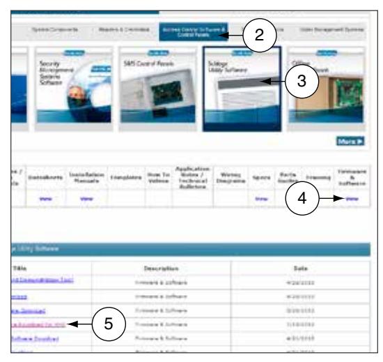
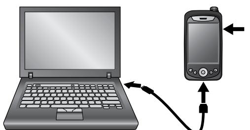
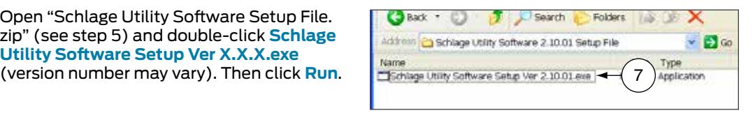
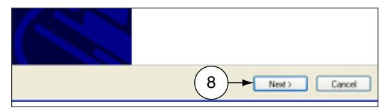
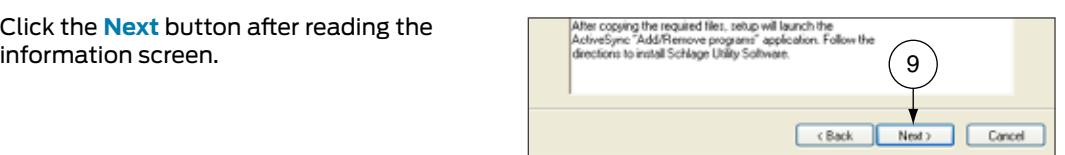
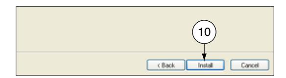
- 11 If the SUS is already installed a message will warn you about the upgrade, click the Yes button to continue. The installation will start. 11
- 12 Click the OK button, when prompted to check your Hand Held Device (HHD).
- 13 Click the Finish button to complete the first stage, and then check the HHD for the final steps.
- 14 On the Hand Held Device (HHD) check if you received a message stating that the software is from an unknown publisher, click the Yes button to continue the installation or jump to the next step if you don't receive the message.
- 15 On the Hand Held Device (HHD) a prompt message will appear asking if you'd like to remove the previous version, click the OK button to continue. The installation will start on the Hand Held Device (HHD)
- 16 A screen prompting for the correct location to install the software will appear; Select: \ProgramStore and click Install . The installation will continue.
- 17 Click the < OK > button on the right top of the screen to close the successfully installed message.
- 18 Before launching the Schlage Utility Software on the HHD disconnect it from the computer.
-
19
On the HHD Go to
Start -> Programs
and double click on the <
Utility Software
> icon to start the Schlage Utility Software (SUS). You'll see a welcoming screen with the actual software version.
- Î Important note: The SUS and the HHD pairing passwords are back to their default values (123456). If your pairing password was different than the default, you would need to change it before trying to reconnect to your device.
-
20
Change the Coupling Password.
- Î See Coupling Password on page 18 for more information.
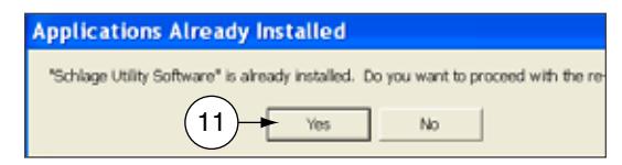
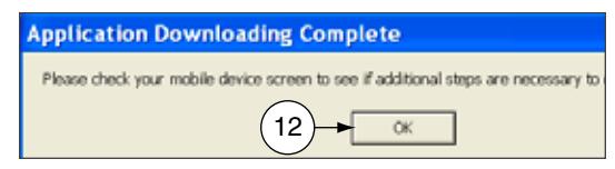
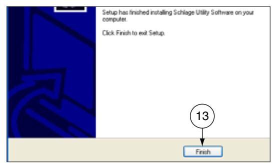
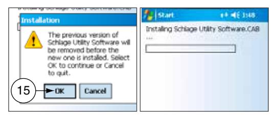
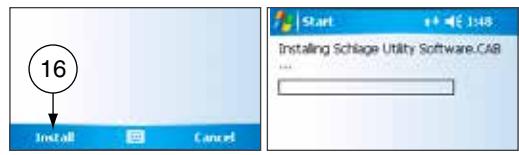
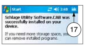
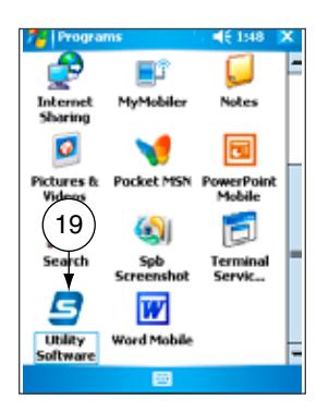
Appendix B: Device Firmware Update
AD-Series On-Line Devices: Over Network Reprogramming (ONR).
Supported Products
PIM400-485-RSI, PIM400-485-VBB, AD-300/301 when wired by RS-485 to the ACP, AD-400/401 when linked to a PIM400-485. Devices must have been updated to A.D.A.60 or later for ONR to be available.
This feature must be provided by the Access Control Software Partner. Talk to your Access Control Provider for more details.
AD-Series and CO-Series Device Firmware Update
Windows XP
Prerequisites
-
ActiveSync should be installed on your PC.
- Î See Synchronization Software on page 9 for more information.
- HHD should have a partnership with ActiveSync.
-
HHD should be already coupled with AD-Series device to be updated.
- Î See "Couple HHD to Lock" or "Couple HHD to PIM400 or PIB300" for more information.
- 1 Browse to www.schlage.com/support .
- 2 Click View under the Firmware & Software column
- 3 Click AD Firmware Package Tools & Docs and save the "AD Firmware Pkg.zip" file to
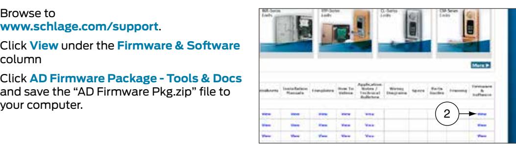
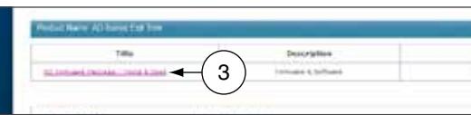
4 Turn on the HHD and connect it to the computer. The Microsoft ActiveSync window will automatically appear.
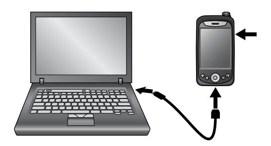
5 In the Microsoft ActiveSync window, click on the Explore button to open the HHD Mobile Device folder.
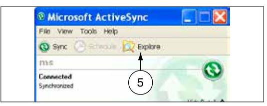
6 Double click on My windows Mobile-Based Device to go to the root directory of the HHD.
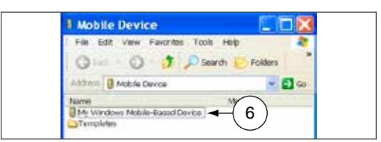
- 7 Copy the ".ffp" firmware file available inside the "AD firmware Pkg.zip" file (see step 3) and paste it inside the root folder <My Windows Mobile-Based Device> .
- 8 Wait for the HHD to synchronize.
- 9 Disconnect the HHD from computer.
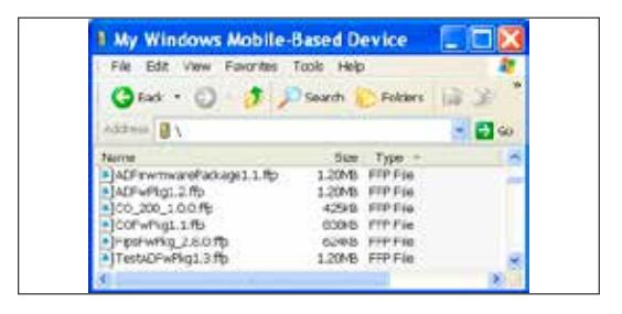
-
10
Go to the device and connect the HHD.
- Î See Connecting the Handheld Device on page 20 for more information.
-
11
Start the Schlage Utility software.
- Î See Start the Schlage Utility Software on page 15 for more information.
-
12
Login as a Manager.
- Î See Log in as a Manager on page 16 for more information.
- 13 Click Device Options at the bottom of the screen.
- 14 Click Firmware Update .
- 15 Select the firmware package you would like to use and click OK .
- 16 A message asking for confirmation to start programming the firmware will appear. Click YES .
- 17 The updating process will begin. The device will then restart. After a few minutes, a message indicating the firmware update was successful will appear.
-
18
Click
OK
.
- Î If the credential reader was changed, a factory default reset is recommended. See the user manual that came with the device for more information. WARNING: A factory default reset will delete all door information from the lock.
Windows 10, Windows 8, Windows 7 and Windows Vista
Prerequisites
-
Microsoft Windows Mobile Device Center should be installed on your PC.
- Î See Synchronization Software on page 9 for more information.
- HHD should have a partnership with Windows Mobile Device Center.
-
HHD should be already coupled with AD-Series device to be updated.
- Î See "Couple HHD to Lock" or "Couple HHD to PIM400 or PIB300" for more information.
- 1 Browse to www.schlage.com/support .
- 2 Click View under the Firmware & Software column.
- 3 Click AD Firmware Package Tools & Docs and save the "AD Firmware Pkg.zip" file to
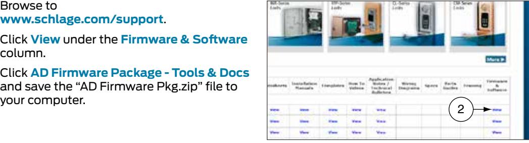
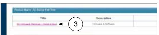
4 Turn on the HHD and connect it to the computer. The Microsoft Windows Mobile Device Center window will automatically appear.

- 5 In the Microsoft Windows Mobile Device Center window, click on File Management and then Browse the contents of your device to open the HHD device contents.
- 6 Double click on \ to go to the root directory of the HHD.

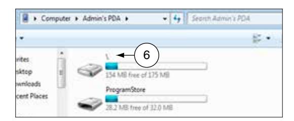
- 7 Copy the ".ffp" firmware file available inside the "AD firmware Pkg.zip" file (see step 3) and paste it inside the root folder ( \ ).
- 8 Wait for the HHD to synchronize.
- 9 Disconnect the HHD from computer.
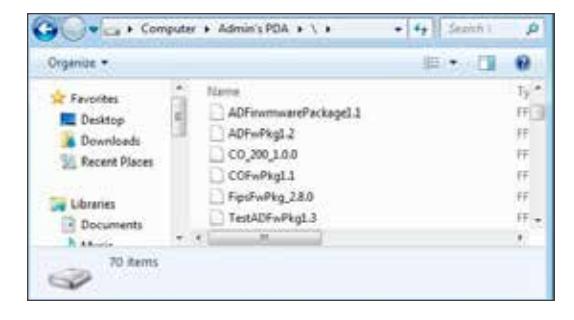
Î NOTE: The SUS will prevent a user from reprogramming a device if batteries are too low and give the warning saying, "The voltage level to complete the firmware update is too low, you must replace the AA batteries and try again." The battery threshold requirements are as follows:
| CO locks | All locks | 4.7V |
|---|---|---|
| AD locks running firmware | 8 battery locks | 8V |
| older than AD.A.50 | 4 battery locks | 5.5V |
| AD locks running firmware | 8 battery locks | 7.2V |
| AD.A.50 or greater | 4 battery locks | 4.7V |
-
10
Go to the device and connect the HHD.
- Î See Connecting the Handheld Device on page 20 for more information.
-
11
Start the Schlage Utility software.
- Î See Start the Schlage Utility Software on page 15 for more information.
-
12
Login as a Manager.
- Î See Log in as a Manager on page 16 for more information.
- 13 Click Device Options at the bottom of the screen.
- 14 Click Firmware Update .
- 15 Select the firmware package you would like to use and click OK .
- 16 A message asking for confirmation to start programming the firmware will appear. Click YES .
- 17 The updating process will begin. The device will then restart. After a few minutes, a message indicating the firmware update was successful will appear.
-
18
Click
OK
.
- Î If the credential reader was changed, a factory default reset is recommended. See the user manual that came with the device for more information. WARNING: A factory default reset will delete all door information from the lock.
Legacy Device Firmware Update
Windows XP
Prerequisites
-
ActiveSync should be installed on your PC.
- Î See Synchronization Software on page 9 for more information.
- HHD should have a partnership with ActiveSync.
- 1 Browse to www.schlage.com/support . Select the legacy product and click View under the Firmware & Software column. Download the latest firmware to your computer.
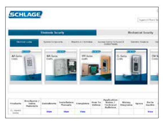
2 Turn on the HHD and connect it to the computer. The Microsoft ActiveSync window will automatically appear.
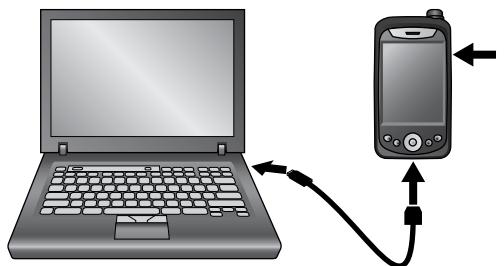
3 In the Microsoft ActiveSync window click on the Explore button to open the HHD My Documents folder.
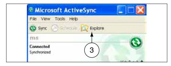
4 Double click on My windows Mobile-Based Device link to go to the root directory of the HHD.
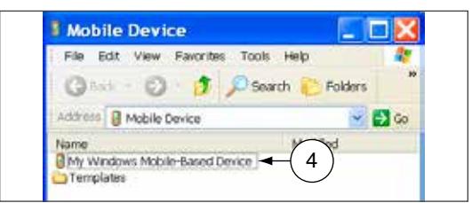
- 5 Copy the ".s19" firmware file available inside the .zip file (see step 1) and paste it inside the My Windows Mobile-Based Device folder.
- 6 Wait for HHD to synchronize.
- 7 Disconnect the HHD from computer.
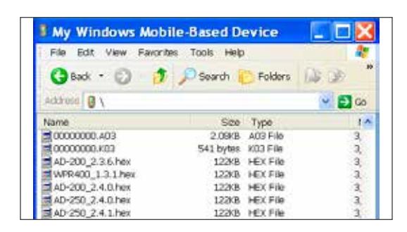
-
8
Go to the device and connect the HHD.
- Î See Connecting the Handheld Device on page 20 for more information.
-
9
Start the Schlage Utility software.
- Î See Start the Schlage Utility Software on page 15 for more information.
-
10
Login as a Manager.
- Î See Log in as a Manager on page 16 for more information.
- 11 Click Device Options at the bottom of the screen.
- 12 Click Firmware Update .
- 13 Select the firmware file you would like to use and click OK .
- 14 Present a valid programming credential to the device and click OK .
- 15 The updating process will begin. The device will then restart. After a few seconds, a message indicating the firmware update was successful will appear.
- 16 Click OK .
- 17 Reset the device to factory defaults before any additional programming. See the user manual that came with the device for more information.
Windows 10, Windows 8, Windows 7 and Windows Vista
Prerequisites
-
Microsoft Windows Mobile Device Center should be installed on your PC.
- Î See Synchronization Software on page 9 for more information.
- HHD should have a partnership with Windows Mobile Device Center.
- 1 Browse to www.schlage.com/support . Select the legacy product and click View under the Firmware & Software column. Download the latest firmware to your computer.
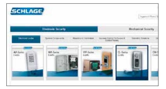
2 Turn on the HHD and connect it to the computer. The Microsoft Windows Mobile Device Center window will automatically appear.
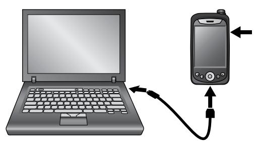
- 3 In the Microsoft Windows Mobile Device Center window click on File Management and then Browse the contents of your device .
- 4 Double click on \ link to go to the root directory of the HHD.

4
- 5 Copy the ".s19" firmware file available inside the .zip file (see step 1) and paste it inside the root folder ( \ ).
- 6 Wait for HHD to synchronize.
- 7 Disconnect the HHD from computer.
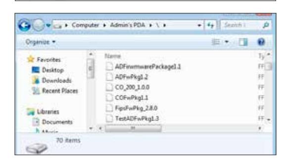
-
8
Go to the device and connect the HHD.
- Î See Connecting the Handheld Device on page 20 for more information.
-
9
Start the Schlage Utility software.
- Î See Start the Schlage Utility Software on page 15 for more information.
-
10
Login as a Manager.
- Î See Log in as a Manager on page 16 for more information.
- 11 Click Device Options at the bottom of the screen.
- 12 Click Firmware Update .
- 13 Select the firmware file you would like to use and click OK .
- 14 Present a valid programming credential to the device and click OK .
- 15 The updating process will begin. The device will then restart. After a few seconds, a message indicating the firmware update was successful will appear.
- 16 Click OK .
- 17 Reset the device to factory defaults before any additional programming. See the user manual that came with the device for more information.
Appendix C: Change Lock Class
AD-Series Locks
Windows XP
Prerequisites
-
ActiveSync should be installed on your PC.
- Î See Synchronization Software on page 9 for more information.
- HHD should have a partnership with ActiveSync.
-
HHD should be already coupled with AD-Series device to be updated.
- Î See "Couple HHD to Lock" for more information.
- 1 Browse to www.schlage.com/support .
- 2 Click View under the Firmware & Software column.
- 3 Click AD Firmware Package Tools & Docs and save the "AD Firmware Pkg.zip" file to
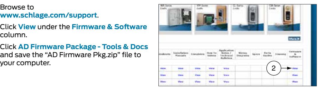
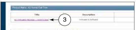
4 Turn on the HHD and connect it to the computer. The Microsoft ActiveSync window will automatically appear.
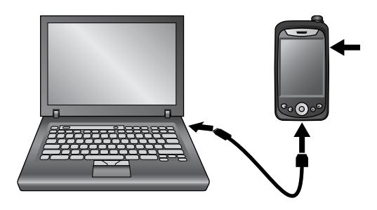
5 In the Microsoft ActiveSync window, click on the Explore button to open the HHD Mobile Device folder.
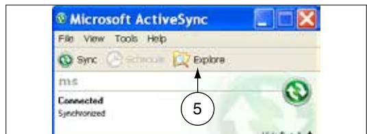
6 Double click on My windows Mobile-Based Device to go to the root directory of the HHD.
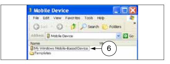
- 7 Copy the ".ffp" firmware file available inside the "AD firmware Pkg.zip" file (see step 3) and paste it inside the root folder <My Windows Mobile-Based Device> .
- 8 Wait for the HHD to synchronize.
- 9 Disconnect the HHD from computer.
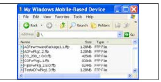
-
10
Go to the lock and connect the HHD.
- Î See Connecting the Handheld Device on page 20 for more information.
-
11
Start the Schlage Utility software.
- Î See Start the Schlage Utility Software on page 15 for more information.
-
12
Login as a Manager.
- Î See Log in as a Manager on page 16 for more information.
- 13 Click Device Options at the bottom of the screen.
- 14 Click Change Lock Class .
- 15 Select the firmware package you would like to use and click Next .
-
16
All available lock classes are displayed on the screen. Select the appropriate lock class and then click
OK
.
- Î Only locks with a magnetic reader can be changed to AD-250.
- 17 A message asking for confirmation to change the lock class will appear. Click Yes .
- 18 The change process will begin. Wait for the lock to restart. Once the confirmation message appears, the process is complete. Click OK .
Windows 10, Windows 8, Windows 7 and Windows Vista
Prerequisites
-
Microsoft Windows Mobile Device Center should be installed on your PC.
- Î See Synchronization Software on page 9 for more information.
- HHD should have a partnership with Windows Mobile Device Center.
-
HHD should be already coupled with AD-Series device to be updated.
- Î See "Couple HHD to Lock" or "Couple HHD to PIM400 or PIB300" for more information.
- 1 Browse to www.schlage.com/support .
- 2 Click View under the Firmware & Software column.
- 3 Click AD Firmware Package Tools & Docs and save the "AD Firmware Pkg.zip" file to
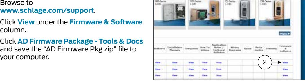
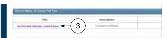
4 Turn on the HHD and connect it to the computer. The Microsoft Windows Mobile Device Center window will automatically appear.
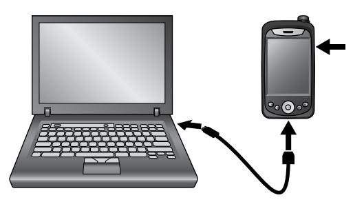
- 5 In the Microsoft Windows Mobile Device Center window, click on File Management and then Browse the contents of your device to open the HHD device contents.
- 6 Double click on \ to go to the root directory of the HHD.
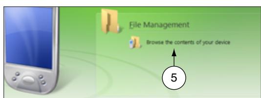
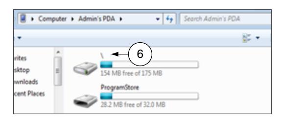
- 7 Copy the ".ffp" firmware file available inside the "AD firmware Pkg.zip" file (see step 3) and paste it inside the root folder ( \ ).
- 8 Wait for the HHD to synchronize.
- 9 Disconnect the HHD from computer.
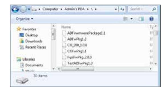
-
10
Go to the lock and connect the HHD.
- Î See Connecting the Handheld Device on page 20 for more information.
-
11
Start the Schlage Utility software.
- Î See Start the Schlage Utility Software on page 15 for more information.
-
12
Login as a Manager.
- Î See Log in as a Manager on page 16 for more information.
- 13 Click Device Options at the bottom of the screen.
- 14 Click Change Lock Class .
- 15 Select the firmware package you would like to use and click Next .
-
16
All available lock classes are displayed on the screen. Select the appropriate lock class and then click
OK
.
- Î Only locks with a magnetic reader can be changed to AD-250.
- 17 A message asking for confirmation to change the lock class will appear. Click Yes .
- 18 The change process will begin. Wait for the lock to restart. Once the confirmation message appears, the process is complete. Click OK .
-
19
Perform a Factory Default Reset of the lock before further use or programming.
- Î See the user manual that came with the device for more information.
Appendix D: Device Template
About Device Template Feature
The Schlage Utility Software (SUS) version 4.10.2 (or higher) includes the Device Template feature.
Users may quickly change and copy "Device Properties" settings across multiple devices so that a group of devices may have the exact same settings applied.
A Device Template file may be initiated from and copied to locks and devices, saved on the HHD, transferred to another HHD, and saved to a computer or network drive.
| Supported Locks and Controllers | |||
|---|---|---|---|
| AD-200 | WPR400 | CO-200 | |
| AD-250 | CT5000 | CO-220 | |
| AD-300 | PIB300 | CO-250 | |
| AD-400 | PIM400-TD2 | ||
| WRI400 | PIM400-485 | ||
Prerequisites
- The HHD used must be coupled before the Device Template file may be saved or retrieved. See Couple HHD to Lock on page 24 for more information.
- The "source" lock or device must be installed and working as desired with all property settings configured as required by the user.
-
The Device Template file can be saved and restored for a
specific hardware class only.
For example:
- Î A Device Template created from an AD-200 Mag Swipe lock will not be available when the SUS is communicating with an AD-200 Prox lock.
- Î A Device Template created from an AD-200 Prox lock will not be available with an AD-300 Prox lock.
Saving a Device Template will also capture the following device status parameters:
- Lock Firmware Version
- Reader Firmware Version
- Lock Serial number
- Reader Serial number
- Card Detection Firmware Version
- Boot Loader Version
- Days Since Installed
- AA Battery Pack Type
- AA Battery Voltage
- Coin Cell Voltage
This information is saved within the Device Template file, and can be viewed with any text viewer by the user.
When naming the Device Template, use normal Windows OS naming conventions.
Create a Device Template
-
1
Connect the HHD to the device with desired properties.
- Î If the device properties have not been programmed, configure the device properties as desired. Refer to AD-Series Lock Properties on page 31 , or CO-Series Lock Properties on page 61 .
- 2 Select Device Options .
- 3 Select Lock Properties for the connected device.
- 4 Select the Edit or Reader tab.
- 5 Select Device Template at the bottom of the screen.
- 6 Select Save From Device to create a Device Template file from the properties of this device.
-
7
Enter a name for the Device Template file.
- Î The name should describe the device configuration this Template is intended to work with and clearly identify the hardware configuration. (Example: AD200-PRK main entrances.)
- 8 Tap OK to save. The SUS will display the location of the saved Template file.
Before copying, a Device Template file must be saved to the SUS, /My Documents/ and must be a hardware configuration match with the receiving device.
The device template file (.dtf) can be shared among devices by copying it from the my documents folder of one of the handhelds, saving it to a computer, and then copying it to the my documents folder of any handhelds that need the template.
Copy a Saved Device Template
-
1
Connect the HHD to the device that will receive the saved properties settings.
- Î Be sure that the receiving device is of the same hardware configuration as that of the source of the Device Template. ( See Prerequisites on page 91 for more information. )
- 2 Select Device Options .
- 3 Select Lock Properties for the connected device.
- 4 Select the Edit or Reader tab.
- 5 Select Device Template at the bottom of the screen.
- 6 Select Save To Device to copy and save a Device Template file to the connected device.
-
7
Select the Device Template file name.
- Î If the Device Template name is not available, check to be sure that the receiving device is of the same hardware configuration as that of the source of the Device Template. ( See Prerequisites on page 91 for more information.)
- 8 Tap OK to save.
- 9 Tap YES on the confirmation window, then tap OK again to finish.
- Î Saving a Device Template file to a PIM or PIB will require re-linking of all previously linked devices
Appendix E: Diagnostic Data Log
About Diagnostic Data Log Feature
The Schlage Utility Software (SUS) version 6.2.1 (or higher) includes the Diagnostic Data Log feature. This new feature provides a simple method for AD-Series customers to quickly gather and save important lockset information in a file. This Diagnostic Data file can then be shared with Technical Services for setup and configuration review and for analysis of issues from the field.
Supported Locks
AD-Series locksets (ONLY) - AD200, AD250, AD300, AD400
Prerequisites
• The HHD used must be coupled before the Diagnostic Data Log file may be saved. See Couple HHD to Lock on page 24 for more information.
Diagnostic Data Log Menu
Schlage Utility Software (SUS) version 6.2.1 (or higher) provides a new Device Options menu. This new Diagnostic Data Log menu will be available when the SUS is connected and communicating with AD-Series locksets. See Diagnostic Data Log Menu .
When the Diagnostic Data log menu is selected, the customer must then provide a name for the file and then select "OK" to continue. See Enter a descriptive name .
Î NOTE: Be sure to provide a sufficiently descriptive name for the file so that you and others will know which AD-Series device and location the file pertains to.
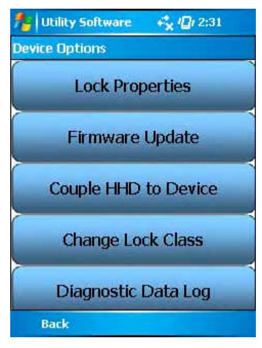
Diagnostic Data Log Menu
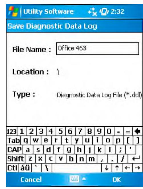
Enter a descriptive name
Next, the SUS will request all data from the AD-Series device and save the file. See Retrieving device data screen shot.
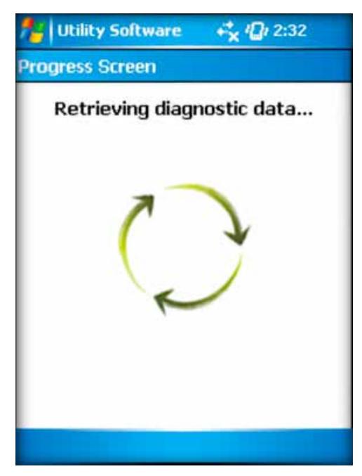
Once the file is generated, the customer should copy and forward the Diagnostic Data file to Technical Services for detailed analysis. See File ready for analysis screen shot.
Î NOTE: CO-Series products and non-lock AD-Series products do not support the Diagnostic Data Log feature
Retrieving device data
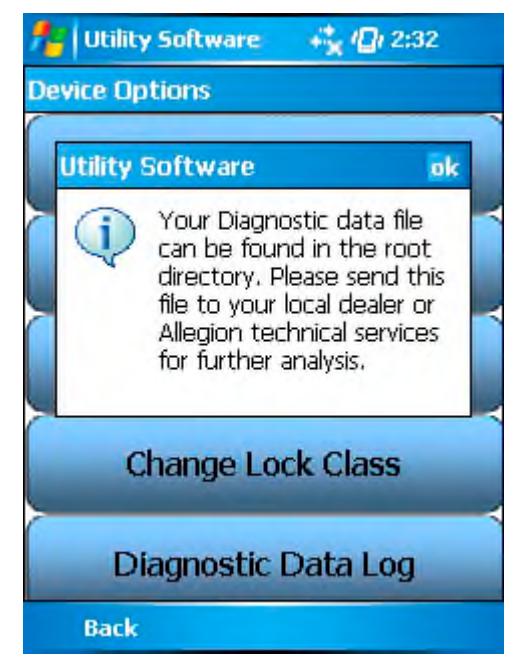
File ready for analysis
Index
| A | C | G |
|
AD-200 5, 6, 24, 31, 91
AD-201 5, 24 |
Cache Mode 74
Card Conversion 74 |
Glossary 74
GUI 75 |
|
AD-250 5, 6, 24, 31, 91
AD-300 5, 6, 24, 35, 91 |
CIP 8, 21, 22, 64, 65
CL 5, 6, 8, 21, 64 |
|
|
AD-301 24
AD-302 5, 24, 31, 39, 41, 50 |
CL993 5
CL5100 5 |
H
Handheld Device 5, 7, 8, 13, 20 |
|
AD-400 5, 24, 39, 91
AD-401 24 |
CL5200 5
CL5500 5 |
Connect 13, 20
Couple to AD-Series Lock 24, 59 |
|
AD-402 5, 24, 31, 39, 41, 50, 97
AD-Series Controllers 24 |
CL5600 5
CL Campus Lock 5, 64 |
Couple to PIM400 25 |
|
Edit Properties 27, 61
Functions 6 |
CM 6, 8, 21, 64, 74
CM993 5 |
Heartbeat 75
HHD 5, 6, 7, 8, 11, 13, 15, 20, 21, 22, 23, 24, |
|
PIM400 Link Mode 28
Program 26, 59 |
CM5100 5
CM5200 5 |
25, 26, 27, 28, 31, 35, 39, 44, 47, 48, 52,
54, 59, 60, 61, 62, 64, 65, 66, 67, 77, 78, |
|
Properties 44
Supported 5, 24 |
CM5500 5
CM5600 5 |
79, 80, 81, 82, 83, 84, 85, 86, 87, 88,
89, 90, 92. See also Handheld Device |
| Update Firmware 79 | CM5700 5 |
HH-Serial 8, 21, 22, 23, 64
HH-USB 8, 13, 24, 25, 59 |
|
View Properties 27, 60
AD-Series Locks 24 |
CM Lock 74
CO-200 5, 6, 59, 91 |
Hi Lo Output 75 |
|
Collect Audits 26
Edit Properties 27, 61 |
CO-220 5, 6, 59, 91
CO-250 5, 6, 59, 91 |
|
|
Edit Reader Properties 27, 61
Functions 6 |
Copy
Device Template 92 |
I
Icons 14 |
|
Program 26, 59
Properties 31, 62 |
Create
Device Template 92 |
|
|
Supported 5, 24
Update Firmware 79 |
CT500 5, 6, 64
CT1000 5, 64 |
K
KC2 5, 6, 64 |
|
View Properties 27, 60
View Reader Properties 27, 61 |
CT5000 5, 6, 24, 91
Customer Service ii |
KC2-5100 5 |
| AD-Series On-Line Devices 79 |
KC2-5500 5
KC2-9000 5 |
|
| D | ||
|
B
BE367 5, 6, 22, 64 |
DCS 74
Delay 74 |
L |
|
Device Template 19, 91
Copy 92 |
Latch Type 75
Legacy Controllers Diagnostics 67 |
|
|
Create 92
Diagnostic Data Log 28, 93 |
Edit Properties 66 | |
| Door Prop Delay 74 |
Functions 6
Program 64 |
|
|
Supported 5, 64
Update Firmware 66, 83 |
||
|
E
Error Codes 69 |
View Properties 65
Legacy Locks |
|
| Extend Unlock 74 |
Collect Audits 65
Diagnostics 67 |
|
| F |
Edit Properties 66
Functions 6 |
|
| Fail Safe 74 |
Program 64
Properties 67 |
|
|
Fail Secure 74
FC Mode 74 |
Supported 5, 64 | |
|
FE210 22
FIPS 5, 24, 31, 39, 41, 50 |
Update Firmware 66, 83
View Properties 65 |
|
|
FIPS201 5, 24, 31, 39, 41, 50
FIPS201-1 5, 24, 31, 39, 41, 50 |
Log In
Manager 16 |
|
FIPS201-2 5, 24, 31, 39 , 41, 50
Operator 16
First 75
Index
M
Microsoft ActiveSync 10, 11 , 80, 83 , 87 Microsoft Windows Mobile Device Center 11 , 12 Mode 75
N
No Purge 74
O
ONR 79 Over Network Reprogramming 79
P
PIB300 iii , 5, 6, 24, 52 , 91 PIM 5 , 6 , 8 , 15 , 23, 25 , 28, 39, 40, 47 , 48 , 64, 67 , 74 , 75, 76 PIM400 iii, 5 , 6 , 24, 25, 28 , 40 , 41 , 45, 48, 49 , 50 PIM400-485 91 PIM400-TD2 91 PIMWA-CV 8, 23 , 65 Programming Password 15, 18 , 24, 25, 59, 78
R
Relatch Time 75 Relock delay 75 Request to Exit 76 Retry 76 RS485 PIM Link a Door 67 Rxt 76 Rxt Sift 76
S
Schlage Utility Software Connection Type 17 Door List 18 Install 13 Language 18 Options 17 Programming Password 18 Start 15 SUS Password 18 Update 13 , 77 , 91 Update Mode 18 SUS Password 15 , 18 Synchronization Folder 11 Synchronization Software 7 , 9, 10, 91 Configure 10 Download 9 Install 9 System Components 8
T
Troubleshooting 68
97 • Schlage • Schlage Utility Software User's Guide
W
WA 8 WAPM 6 , 76 Warranty iii WPR 64 WPR2 64 WPR400 5, 24 , 44 , 91 WRI 64 WRI400 5, 24, 91 WSM 64
About Allegion
Allegion (NYSE: ALLE) creates peace of mind by pioneering safety and security. As a $2 billion provider of security solutions for homes and businesses, Allegion employs more than 7,800 people and sells products in more than 120 countries across the world. Allegion comprises 23 global brands, including strategic brands CISA®, Interflex®, LCN®, Schlage® and Von Duprin®.
For more, visit www.allegion.com .