Trine EN400 & EN400RP Electric Strike Installation Instructions
Open the original PDF document
View PDFTROUBLESHOOTING
| Possible Trouble | Probable Cause | Suggested Remedy | |
|---|---|---|---|
|
Door lockset is not
secured by Electric Strike |
1) Centerline of lockset is not
properly aligned to the centerline of the electric strike. |
Check for proper cutout installation of Electric Strike by
referring to template and door frame and lockset position. |
|
| 2) Latch does not project | Check for excessive gap between door and jamb. | ||
|
properly into the cavity of the
electric strike |
Check that lockset is compatible with EN series cavity and requirements. If necessary, use other type of lockset
or Electric Strike (refer to Trine Catalog for more information). |
||
|
3) Latch Spring broken
or missing |
Hold Electric Strike so that wiring faces down and apply pressure to Latch. Verify that Latch releases and that
there is sufficient Spring tension to push it to closed positionwhen released. If Latch does not have Spring tension, disassemble Electric Strike and inspect for improperly installed or broken Spring. |
||
|
Electric Strike
does no energize |
1) Wiring to electric strike is
open or shorted. |
Check that electrical connections are secure and that no fraying has occurred during installation. Use voltmeter
to verify that Electric Strike is receiving energizing voltage and that wiring is not shorted. |
|
| (activate) |
2) Insufficient voltage to
electric strike. |
Verify that voltage rating on Electric Strike label is compatiblewith voltage from secondary transformer
(12V or 24V). If voltages do not match, either replace transformer or change Electric Strike or Coil Assembly. |
|
| Use voltmeter to verify that Electric Strike is receiving proper voltage and that wiring is not shorted. | |||
|
If voltage is too low because wire size is too small for length or wiring to Electric Strike (see
wiring-length data on previous page), either replace wiring or use transformer with higher VA rating. |
|||
|
3) Slider does not move when
coil receives proper voltage |
Using an OHM meter, verify that resistance of the Coils matches the chart on page 3. If Coil is open (burned out),
verify that transformer for Electric Strike has correct voltage current AC/DC and is wired correctly. AC Coils do not operate at continuous duty, or on DC voltage. |
||
| Check that Slider (2) floats freely, as follows: | |||
|
Remove Electric Strike from jamb and hold with wires facing up. Test that Strike is locked by applying pressure
to Latch. Then turn Strike upside down with wires facing down and verify that Latch opens freely by applying pressure. The locking Slider (#2) must float freely for unit to operate properly. |
|||
|
Electric Strike energizes
but does not disengage |
1) Lockset is applying pressure
to electric strike, preventing latch from releasing. |
Check for proper cutout installation of Electric Strike. Latch requires proper clearance to open correctly and
provide path for Lockset Latch to engage Strike. |
|
| the lockset | Check that Lockset Latch is not binding to bottom of Strike cavity due to door sag. | ||
|
Check if foam insulation or the materials around door jamb are preventing door from closing flush, causing
door to put pressure on Latch. |
|||
FOR ADDITIONAL INFORMATION, HELP, ACCESS TO SPECS ON A OUR FULL LINE OF PRODUCTS, OR ADDITIONAL CONTACT OPTIONS PLEASE VISIT OUR WEBSITE www.trineonline.com
V. 18.0111
TRINE ACCESS TECHNOLOGY
PHONE: (203) 730-1756 FAX: (203) 730-1781 2 PARKLAWN DRIVE, BETHEL, CT 06801 email: customerservice@trineonline.com website: www.trineonline.com
EN400 & EN400RP ELECTRIC STRIKE

INSTALLATION INSTRUCTIONS
Congratulations on the purchase of this quality TRINE security product. This product has been designed to install easily, perform reliably, and provide years of trouble free security.
BEFORE proceeding with your installation, please review the following list of features. If you have any questions after reading this document please call TRINE's TECHNICAL SUPPORT (203) 730-1756 EXT. 447, or visit the TRINE web site at www.trineonline.com
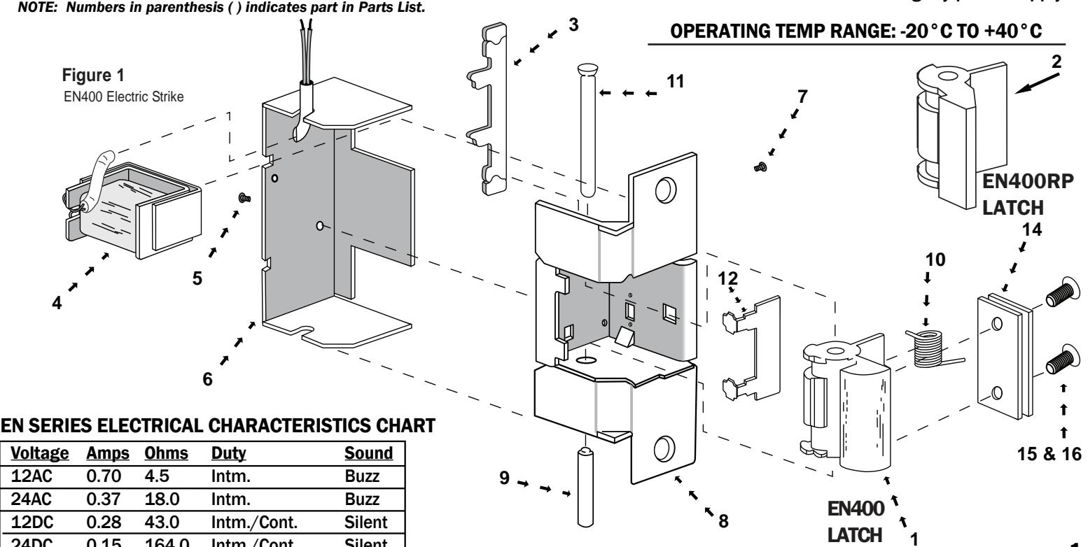
PARTS LIST
| Index No. Name Part | Number | |
|---|---|---|
| 1 | EN400 Latch | EN-LCH |
| 2 | EN400RP Latch | EN- RPLCH |
| 3 | Slider | EN-SLR |
| 4 | Coil Assembly (12V) | EN-CA-12DC or EN-CA-12AC |
| Coil Assembly (24V) | EN-CA-24DC or EN-CA-24AC | |
| 5 | Screws (2) #4-40 x 1/8" (Cover) EN-SCR 1/8 | |
| 6 | Frame Cover | EN-FR.C |
| 7 | Screws #4-40 x 1/4" (Coil) | EN-SCR 1/4 |
| 8 | Frame ** | EN-FR400 |
| 9 | Assembly Pin* | EN-ASS.PN |
| 10 | Spring | EN-SPR |
| 11 | Latch Pivot Pin | EN-LCH-PV-ST |
| 12 | Slider Guard | EN-GRD |
| 13 | Mounting Screws (2) #12-24 x 1/2" EN-MTS | |
| 14 | Shim Kit (3) 1/16" Shim | EN-UNV-SHIM |
| 15 | Shim Screws (2) #6-32 x 1/4" | EN-SHIM-SCR-S |
| 16 | Shim Screws (2) #6-32 x 3/8" | EN-SHIM-SCR-L |
24DC 0.15 164.0 Intm./Cont. Silent
UL LISTED - 10B fire rated (class A, 3-hour, Single Swing Doors) -- [Except EN400RP configuration]
UL LISTED - 294 Access Control System Units
UL LISTED - 1034 Burglary Resistant Locking Mechanism for Indoor or Outdoor Use
ANSI/BHMA - A156.5 - 1992 - 4-7/8" x 1-1/4" Fits Cutout Specification A115.1 (with Slight Jamb Modification)
BHMA - Grade 1
NYC MEA - 79-01-E
NOTE: UL fire listing is void when using fail safe action or RP latch (400RP) for Rim Panic Devices.
All models have bene evaluated for the following performance levels per UL 294 6th edition:
|
Destructive
Attack |
Access Control
Line Security |
Endurance Standby Power | |
|---|---|---|---|
| I | I | IV | I |
Listed Class 2 Power-limited burglary power supply
1
.1
.4
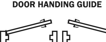
RIGHT HAND REVERSE (ORDER LH) LEFT HAND REVERSE (ORDER RH)
HANDING OF DOOR IS ALWAYS DETERMINED FROM THE OUTSIDE
HANDING DETERMINATION
Door handing is determined by the position of the hinges, as viewed from the outside of the room or building. If the door hinges are on the left, the door is termed left handed: if the door hinges are on the right, the door is termed right handed. Also a door is either inswinging (opens into the room), or outswinging (opens to the outside of the room).
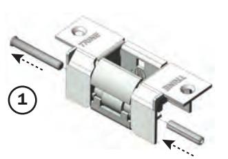
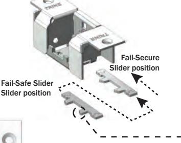
400 LATCH FOR CYLINDRICAL & MORTISE LOCKS LATCH ASSEMBLY Prepare the Latch for
assembly. Position the
Spring as shown and
pass the assembly pin
through the two parts.
Latch and Latch
Insert the Slider as
Fail-Secure or
Fail-Safe position
as shown.
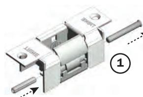
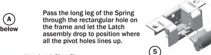
RP LATCH (A) FOR RIM PANIC SWAP LATCHES DEVICES
At 5 (Below) you may switch out the standard Cylindrical/Mortise Latch for the RP (rim panic) Latch.
Note: RP Latch is NOT Fire Rated (it is Outdoor rated)
RIGHT HAND ASSEMBLY
Fail-Safe
Assembly
Pin
(2)
Disassemble the Back Cover and the solenoid of the Left Hand configured EN strike.
Using the Assembly Pin, push the Latch Pivot Pin out.
Take the Latch & Spring and the Slider Guard out of the frame.
LEFT HAND ASSEMBLY
Disassemble the Back Cover and the solenoid of the Right Hand configured EN strike.
Using the Assembly Pin, push the
Take the Latch & Spring and the Slider
Dimple shows Slider position
Align the Slider with the pick guard ribs as shown.

Assemble the Slider Guard over the Slider.
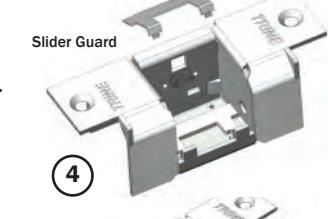
Assemble the Slider Guard over the Slider.


Insert the Latch Pivot Pin making sure that the flared pin head is towards the right as shown.
Pass the Latch Pivot Pin through the Frame, Latch and Spring.
(The assembly pin will fall off the opposite end. Save this pin for future use.)

Finish the assembly by installing the Cover and securing it with the two assembly Screws.
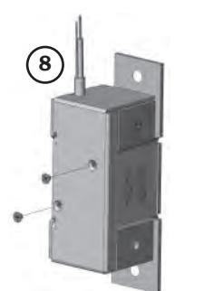
Assemble the Solenoid and secure it with the solenoid Screw as shown.
Insert the Latch Pivot Pin
Frame, Latch and Spring.
this pin for future use.)
making sure that the flared pin
head is towards the left as shown.
Pass the Latch Pivot Pin through the
Finish the assembly by installing the Cover and securing it with the two assembly Screws.
Latch Pivot Pin out.
Guard out of the frame.
Figure 4. Position of Electric Strike for Left Hand Inswinging and Right Hand Outswinging Door
as shown in figure (4).
NOTE
The EN Electric Strike must be installed with coil assembly up (wiring toward top of unit). In this position, the Electric Strike will be locked without power, Fail Secure, or locked with power, Fail Safe action. Before performing Handing Procedure, view Electric Strike in up position (wire leads at top) to determine if a handing change is required.
The position of the Electric Strike in the door
and a lefthanded door. For these installations,
In a similar manner, the position of the Electric
Electric Strike position in the door jamb will be
Strike in the door jamb will be the same for a
lefthanded reverse bevel door and a right
-handed door. For these installations, the
Figure 3.
Position of
Electric Strike
for Right Hand
Inswinging and Left Hand
Outswinging
Door
the Electric Strike position in the door jamb
will be as shown in Figure 3.
Cont... Page 2 Door Handing Determination INSTALLATION PROCEDURE:
-
For new or replacement installation in wood jamb will be the same for a right-handed door or metal jambs.
- 1. Verify that voltage rating of Electric Strike is compatible with supply voltages of installtion. Coil voltages are color coded.
| WIRE LEAD | CODE/STRIPE |
|---|---|
| 12AC | Blue/Orange Stripe |
| 12DC | 2 Orange Stripe |
| 24AC | Blue/Black Stripe |
| 24DC | 2 Black Stripe |
2. Using template supplied with Electric Strike. mark door jamb for cutout and screw holes.
For proper installation, center line of latches must be aligned with center line of Electric Strike.
- 3. Prepare door frame (cut out jamb if required) for Electric Strike. Leave sufficient space for splicing between power supply wiring and Electric Strike wiring.
- 4. If required, run new wiring to door frame mounting hole. See figure 10 for typical wiring installations. Refer to wiring chart below for correct wire size. (Total wiring length includes routing to door-release push button).
Total Wiring Length
| To Transformer | 12V | 24V |
|---|---|---|
| Up to 50 Ft | 18AWG | 20AWG |
| 50 to 150 ft | 16AWG | 18AWG |
| 150 to 300 ft | 14AWG | 16AWG |
| 300 to 600 ft | 12AWG | 14AWG |
For DC operation, to obtain an audible signal when Electric Strike is energized. install buzzer type BZ-12 for 12VDC operation, or BZ-24 for 24VDC operation (purchased seperately), as illustrated in figure 10. 5. Hold Electric Strike upright (wiring toward top) and determine if handing is required. If so, perform handing procedure.
- 6. Splice Electric Strike wiring to supply wiring. Secure with wire nuts (supplied).
- 7. For wood and aluminum door jambs, drill pilot holes for securing Electric Strike to door jamb. For steel and aluminum door iambs, secure Electric Stike to existing mounting tabs.
- 8. Install Electric Strike into door jamb and secure with flat head mounting screws (supplied).
- 9. Verify that door operates correctly when Electric Strike is energized and not energized.
NOTE
- 1. Rectifier can be located either between transformer and push button, or between push button and electric strike.
- 2. Use either a silicon rectifier or a current regulating rectifier for converting the AC voltage at the transformer secondary to the DC for operating the electric strike.
SAMPLE WIRING DIAGRAMS FOR THE EN SERIES
Figure 10a. USING DC TRANSFORMER
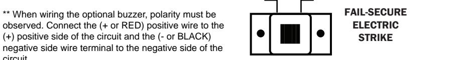
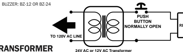
Figure 10b. USING ACTRANSFORMER
* The rectifier can be positioned before of after the push button in the circuit. The LC module can ONLY be positioned after the push button as shown above.
*** When wiring the optional buzzer, polarity must be observed. Connect the (+ or RED) positive wire to the (+) positive side of the circuit and the (- or BLACK) negative side wire terminal to the negative side of the circuit
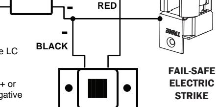
.3
circuit.